Front Matter
TM 9-2815-225-34&P
WARNING SUMMARY
Operating a deadlined vehicle without preliminary inspection will cause further damage to a malfunctioning component and possible injury to personnel. Use extreme care when handling heavy parts. Provide adequate support and use assistance during procedure. Ensure that any lifting device used is in good operating condition and of suitable load capacity. Keep clear of heavy components supported only by lifting device. Failure to comply may result in death or injury to personnel. Compressed air used for cleaning purposes must not exceed 30 psi. Use only with effective chip guarding and personal protective equipment (goggles/shield, gloves, etc.). Failure to comply may result in death or injury to personnel. When removing hood tilt assist cables, hood must be supported. Failure to comply may result in damage to equipment or injury to personnel. Use pry bars to free engine hangups or snags. Do not use hands. Failure to comply may result in damage to equipment or death or injury to personnel. Use extreme care during engine accessory removal. Engine parts are heavy. Failure to comply may result in death or injury to personnel. Eye protection must be worn when using wire brush for cleaning. Failure to comply may result in injury to personnel. Wear rubber gloves when removing piston pin to prevent burns from hot water or hot piston. Failure to comply may result in injury to personnel Oil pump pressure regulator spring is under tension. Remove oil pump pressure regulator slowly and wear proper eye protection. Failure to comply may result in injury to personnel. Oil pump pressure regulator spring is under tension. Install oil pump pressure regulator screw slowly and wear proper eye protection. Failure to comply may result in injury to personnel. Oil pump pressure regulator spring is under tension. Remove oil pump bypass screw slowly and wear proper eye protection. Failure to comply may result in injury to personnel. Turbine wheel machined edges are very sharp. Wear protective gloves when handling turbine wheel. Failure to comply may result in injury to personnel. Control valve cover is under control valve outer spring pressure. Hold cover securely when removing screws. Failure to comply may cause injury to personnel. Slave piston spring is highly compressed. Be extremely careful during disassembly. Personal injury can occur if spring force is not controlled. Use gloves during piston pin installation if piston has been soaked in hot water. Failure to comply may result in injury to personnel. Do not perform fuel system procedures while smoking or within 50 ft (15.2 m) of sparks or open flame. Diesel fuel is flammable and may explode. Failure to comply may result in injury or death to personnel.
WARNING SUMMARY (Contd)
Allow adequate ventilation for engine exhaust gases. Do not perform fuel system procedures while smoking or within 50 ft (15.2 m) of sparks or open flame. Diesel fuel is flammable and may explode. Failure to comply may result in serious injury or death to personnel. Use extreme caution during disassembly or assembly; engine components are heavy. Failure to comply may result in damage to equipment or injury to personnel. All personnel must stand clear during lifting operations. A snapped chain or swinging or shifting load may result in injury to personnel. When installing hood tilt assist cables, hood must be supported. Failure to comply may result in damage to equipment or injury to personnel. Compressed air source must not exceed 30 psi (207 kPa). Wear eyeshields when cleaning with compressed air. Failure to comply may result in injury to personnel.
LIST OF EFFECTIVE PAGES/WORK PACKAGES
The date of issue for original pages/work pages for this TM is:
Original 21 July 2005
TOTAL NUMBER OF PAGES IN THIS PUBLICATION IS 651.
TOTAL NUMBER OF WORK PACKAGES IS 62.
THE PAGES/WORK PACKAGES CONSIST OF THE FOLLOWING:
Page No. . . . . . . . . . . . . .Change No. * Warning a–Warning b . . . . . . . . . . . . . .0 A . . . . . . . . . . . . . . . . . . . . . . . . . . . . . . . .0 B blank . . . . . . . . . . . . . . . . . . . . . . . . . . .0 i . . . . . . . . . . . . . . . . . . . . . . . . . . . . . . . . .0 ii blank . . . . . . . . . . . . . . . . . . . . . . . . . . .0 iii–vii . . . . . . . . . . . . . . . . . . . . . . . . . . . . .0 viii blank . . . . . . . . . . . . . . . . . . . . . . . . .0 WP 0001 00–WP 0062 00 . . . . . . . . . . .0 Index 1–Index 3 . . . . . . . . . . . . . . . . . . .0 Index 4 blank . . . . . . . . . . . . . . . . . . . . .0 0
*Zero in this column indicates original page.
A/B blank
*Supersedes copy dated 28 August 2001 HEADQUARTERS,
DEPARTMENT OF THE ARMY
WASHINGTON, D.C., 21 July 2005
DIRECT SUPPORT AND GENERAL SUPPORT
MAINTENANCE MANUAL INCLUDING
REPAIR PARTS AND SPECIAL
TOOLS LIST (RPSTL)
FOR
ENGINE, DIESEL: 6 CYLINDER IN-LINE
TURBOCHARGED, CUMMINS MODEL NTC-400
BIG CAM I
(NSN 2815-01-082-8125)
BIG CAM III
(NSN 2815-01-142-2745)
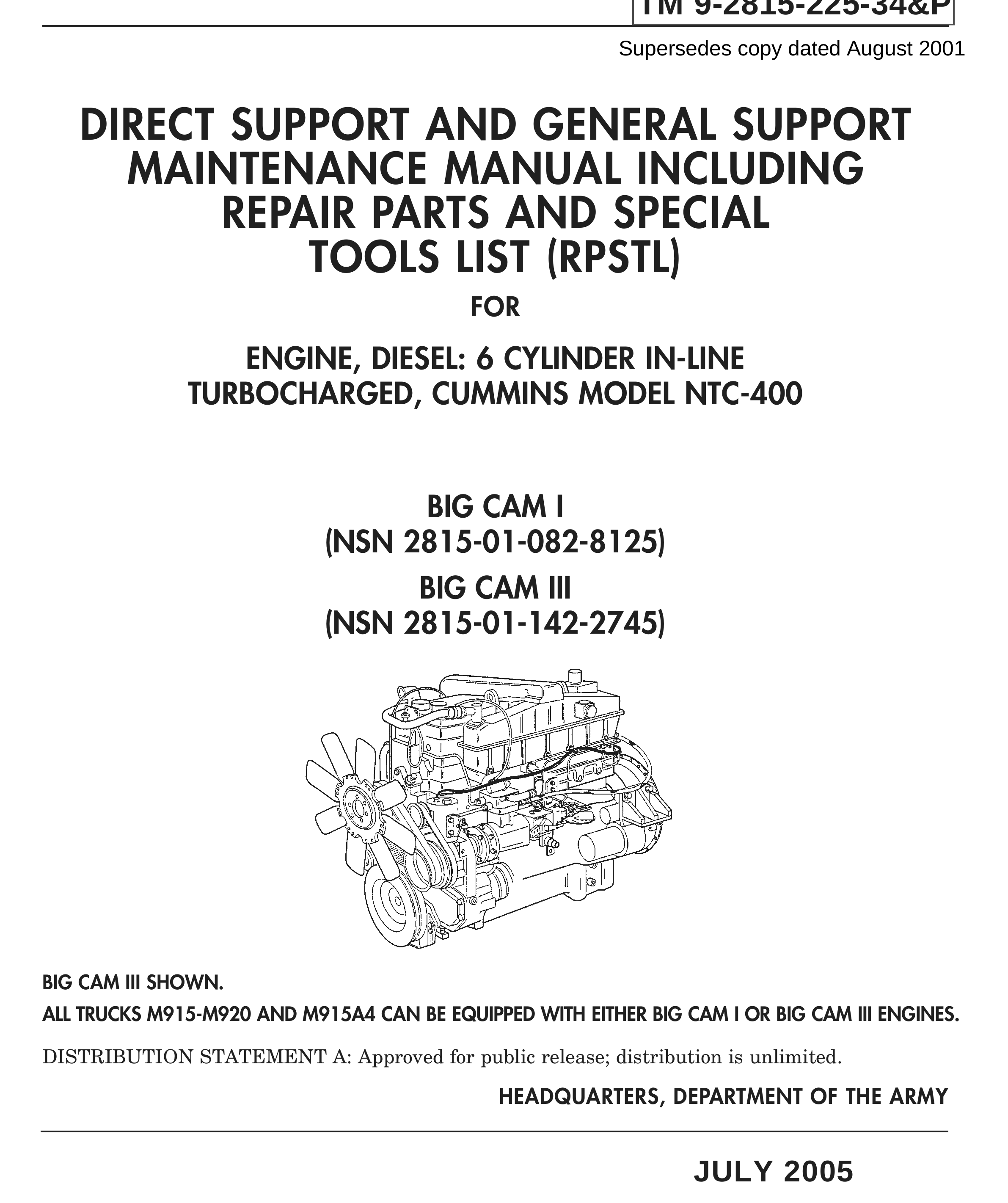
ALL TRUCKS M915-M920 AND M915A4 CAN BE EQUIPPED WITH EITHER BIG CAM I OR
BIG CAM III ENGINES.
REPORTING ERRORS AND RECOMMENDING IMPROVEMENTS
You can help improve this publication. If you find any mistakes or if you know of a way to improve the procedures, please let us know. Submit your DA Form 2028 (Recommended Changes to Publications and Blank Forms), through the Internet, on the Army Electronic Product Support (AEPS) website. The Internet address is http://aeps.ria.army.mil. If you need a password, scroll down and click on “ACCESS REQUEST FORM.” The DA Form 2028 is located in the ONLINE FORMS PROCESSING section of the AEPS. Fill out the form and click on SUBMIT. Using this form on the AEPS will enable us to respond quicker to your comments and better manage the DA Form 2028 program. You may also mail, fax or E-mail your letter or DA Form 2028 direct to: AMSTA-LC-CI Tech Pubs, TACOM-RI, 1 Rock Island Arsenal, Rock Island, IL 61299-7630. The E-mail address is TACOM-TECH- PUBS@ria.army.mil. The fax number is DSN 793-0726 or Commercial (309) 782-0726.
DISTRIBUTION STATEMENT A: Approved for public release; distribution is unlimited.
TABLE OF CONTENTS
Work Package/Page No.
How to Use This Technical Manual (TM) . . . . . . . . . . . . . . . . . . v
CHAPTER 1 GENERAL INFORMATION, EQUIPMENT
DESCRIPTION, AND THEORY OF OPERATION
General Information . . . . . . . . . . . . . . . . . . . . . . . . . . . . . . . . . . . WP 0001 00-1 Equipment Characteristics, Capabilities, and Features . . . . . . . WP 0002 00-1 Theory of Operation . . . . . . . . . . . . . . . . . . . . . . . . . . . . . . . . . . . . WP 0003 00-1
CHAPTER 2 TROUBLESHOOTING PROCEDURES
Engine Troubleshooting . . . . . . . . . . . . . . . . . . . . . . . . . . . . . . . . . WP 0004 00-1
CHAPTER 3 MAINTENANCE INSTRUCTIONS
Preventive Maintenance Checks and Services (PMCS) Introduction . . . . . . . . . . . . . . . . . . . . . . . . . . WP 0005 00-1 Preventive Maintenance Checks and Services (PMCS) Instructions . . . . . . . . . . . . . . . . . . . . . . . . . . WP 0006 00-1 Big Cam I Engine Removal . . . . . . . . . . . . . . . . . . . . . . . . . . . . . . WP 0007 00-1 Big Cam III Engine Removal . . . . . . . . . . . . . . . . . . . . . . . . . . . . WP 0008 00-1 Mounting Engine on Maintenance Stand . . . . . . . . . . . . . . . . . . . WP 0009 00-1 Engine Accessories Removal . . . . . . . . . . . . . . . . . . . . . . . . . . . . . WP 0010 00-1 Cylinder Head and Cylinder Head Components Removal . . . . . WP 0011 00-1 Cylinder Block Components Removal . . . . . . . . . . . . . . . . . . . . . . WP 0012 00-1 Cylinder Block . . . . . . . . . . . . . . . . . . . . . . . . . . . . . . . . . . . . . . . . WP 0013 00-1 Cylinder Head . . . . . . . . . . . . . . . . . . . . . . . . . . . . . . . . . . . . . . . . WP 0014 00-1 Vibration Damper and Crankshaft Pulley Cleaning and Inspection . . . . . . . . . . . . . . . . . . . . . . . . . . . . . . WP 0015 00-1 Crankshaft Cleaning and Inspection . . . . . . . . . . . . . . . . . . . . . . WP 0016 00-1 Flexplate, Flywheel, Flywheel Housing, and Rear Cover Cleaning and Inspection . . . . . . . . . . . . . . . . . . . . . . . . . . . . . . WP 0017 00-1 Pistons, Connecting Rods, and Bearings . . . . . . . . . . . . . . . . . . . WP 0018 00-1 Camshaft, Camshaft Followers, and Push Rods . . . . . . . . . . . . . WP 0019 00-1 Rocker Levers and Rocker Lever Housing . . . . . . . . . . . . . . . . . . WP 0020 00-1 Oil Cooler . . . . . . . . . . . . . . . . . . . . . . . . . . . . . . . . . . . . . . . . . . . . WP 0021 00-1 Oil Pan, Dipstick, Oil Suction Tubes, and Breather Tube . . . . . WP 0022 00-1 Oil Pump . . . . . . . . . . . . . . . . . . . . . . . . . . . . . . . . . . . . . . . . . . . . . WP 0023 00-1 Air Aftercooler . . . . . . . . . . . . . . . . . . . . . . . . . . . . . . . . . . . . . . . . WP 0024 00-1 Exhaust Manifold . . . . . . . . . . . . . . . . . . . . . . . . . . . . . . . . . . . . . . WP 0025 00-1 Turbocharger . . . . . . . . . . . . . . . . . . . . . . . . . . . . . . . . . . . . . . . . . WP 0026 00-1 Turbocharger HT-3B . . . . . . . . . . . . . . . . . . . . . . . . . . . . . . . . . . . WP 0027 00-1 Front Gear Cover . . . . . . . . . . . . . . . . . . . . . . . . . . . . . . . . . . . . . . WP 0028 00-1 Accessory Drive and Accessory Drive Pulley . . . . . . . . . . . . . . . . WP 0029 00-1 Engine Retarder . . . . . . . . . . . . . . . . . . . . . . . . . . . . . . . . . . . . . . . WP 0030 00-1
TABLE OF CONTENTS (Contd)
Work Package/Page No.
CHAPTER 3 MAINTENANCE INSTRUCTIONS (Contd) Air Compressor . . . . . . . . . . . . . . . . . . . . . . . . . . . . . . . . . . . . . . . . WP 0031 00-1 Fuel Injector . . . . . . . . . . . . . . . . . . . . . . . . . . . . . . . . . . . . . . . . . . WP 0032 00-1 Fuel Pump Disassembly . . . . . . . . . . . . . . . . . . . . . . . . . . . . . . . . WP 0033 00-1 Solenoid Valve . . . . . . . . . . . . . . . . . . . . . . . . . . . . . . . . . . . . . . . . WP 0034 00-1 Fuel Damper and Head . . . . . . . . . . . . . . . . . . . . . . . . . . . . . . . . . WP 0035 00-1 Fuel Gear Pump . . . . . . . . . . . . . . . . . . . . . . . . . . . . . . . . . . . . . . . WP 0036 00-1 Fuel Pump Governor Spring . . . . . . . . . . . . . . . . . . . . . . . . . . . . . WP 0037 00-1 Fuel Pump Front Cover and Governor . . . . . . . . . . . . . . . . . . . . . WP 0038 00-1 Fuel Pump Main Housing . . . . . . . . . . . . . . . . . . . . . . . . . . . . . . . WP 0039 00-1 Fuel Pump Assembly . . . . . . . . . . . . . . . . . . . . . . . . . . . . . . . . . . . WP 0040 00-1 Water Pump . . . . . . . . . . . . . . . . . . . . . . . . . . . . . . . . . . . . . . . . . . WP 0041 00-1 Cylinder Block Components Installation . . . . . . . . . . . . . . . . . . . WP 0042 00-1 Cylinder Head and Cylinder Head Components Installation . . . WP 0043 00-1 Fuel Pump Testing and Calibration . . . . . . . . . . . . . . . . . . . . . . . WP 0044 00-1 Engine Accessories Installation . . . . . . . . . . . . . . . . . . . . . . . . . . WP 0045 00-1 Removing Engine from Maintenance Stand . . . . . . . . . . . . . . . . WP 0046 00-1 Engine Testing . . . . . . . . . . . . . . . . . . . . . . . . . . . . . . . . . . . . . . . . WP 0047 00-1 Big Cam III Engine Installation . . . . . . . . . . . . . . . . . . . . . . . . . . WP 0048 00-1 Big Cam I Engine Installation . . . . . . . . . . . . . . . . . . . . . . . . . . . WP 0049 00-1 Big Cam III Modification Kit Installation Instructions . . . . . . . WP 0050 00-1 General Maintenance Instructions . . . . . . . . . . . . . . . . . . . . . . . . WP 0051 00-1 Illustrated List of Manufactured Items . . . . . . . . . . . . . . . . . . . . WP 0052 00-1 Torque Limits . . . . . . . . . . . . . . . . . . . . . . . . . . . . . . . . . . . . . . . . . WP 0053 00-1 Wear Limits . . . . . . . . . . . . . . . . . . . . . . . . . . . . . . . . . . . . . . . . . . WP 0054 00-1
CHAPTER 4 SUPPORTING INFORMATION
References . . . . . . . . . . . . . . . . . . . . . . . . . . . . . . . . . . . . . . . . . . . . WP 0055 00-1 Repair Parts Introduction . . . . . . . . . . . . . . . . . . . . . . . . . . . . . . . WP 0056 00-1 Repair Parts . . . . . . . . . . . . . . . . . . . . . . . . . . . . . . . . . . . . . . . . . . WP 0057 00-1 Repair Parts and Special Tools List (RPSTL) . . . . . . . . . . . . . . . WP 0058 00-1 National Stock Number (NSN) Index . . . . . . . . . . . . . . . . . . . . . . WP 0059 00-1 Expendable and Durable Items . . . . . . . . . . . . . . . . . . . . . . . . . . . WP 0060 00-1 Tools and Special Tools . . . . . . . . . . . . . . . . . . . . . . . . . . . . . . . . . WP 0061 00-1 Mandatory Replacement Parts . . . . . . . . . . . . . . . . . . . . . . . . . . . WP 0062 00-1
Index . . . . . . . . . . . . . . . . . . . . . . . . . . . . . . . . . . . . . . . . . . . . . . . . Index-1
HOW TO USE THIS
TECHNICAL MANUAL (TM)
INTRODUCTION
This section explains the basic organization, contents, format, and special features of this Technical Manual (TM). After reading this section, spend some time reviewing the TM to familiarize yourself with the contents and layout. This will enable you to locate information easily and reduce the time needed to complete required procedures.
ORGANIZATION AND CONTENTS
This TM is divided into four main chapters. Chapter 1 presents general information and preliminary data; chapter 2 contains troubleshooting procedures; chapter 3 includes maintenance instructions; and chapter 4 provides supporting tool, equipment, and parts information. The following table provides an overview of the material contained in each chapter of this TM.
Table 1. TM Contents Chapter 1 • Basic information about the component, along with general guidelines and criteria for inspection and repair or replacement • Detailed equipment description and data • Theory of operation Chapter 2 • Detailed troubleshooting procedures
Chapter 3 • Detailed maintenance instructions for disassembly, inspection, repair or replacement, and assembly Chapter 4 • Supporting information covering repair parts, expendable and durable items, tools and special tools, and mandatory replacement parts list
You can locate specific information in the TM by using either the Table of Contents, located at the front of the TM, or the alphabetical subject Index, located at the back of the TM.
HOW TO USE THIS TECHNICAL MANUAL (TM) (Contd)
FORMAT
Work Package (WP) Format Each chapter in this TM is divided into WPs, which group data into stand-alone informational or task- oriented units. Here are some important things to know about the WP format: • Each WP has its own identification number, which appears in the upper right corner of each page. WPs are numbered sequentially throughout the manual. • Each WP starts with page number 1. Page numbers appear at the bottom of the pages, following the WP number. • Informational WPs begin with a listing of the specific topics covered, in the order in which they appear in the WP. This listing provides a quick overview of each WP and enables you to locate specific information easily. • Each task-oriented WP begins with an Initial Setup list that identifies all tools, mandatory replacement parts, personnel, and other materials needed to complete the procedure in the WP. Before you begin a procedure, review the Initial Setup information to ensure that all requirements have been met. • Task-oriented WPs (maintenance procedures) appear in the manual in the order of logical work sequence. This format makes the TM easy to follow and helps improve efficiency as you progress through the procedures.
Text and Illustration Modular Layout Throughout this TM, maintenance procedures are set up in two-page modular layouts. This means that illustrations appear either on the same page as, or on the page facing, the step you are performing. This feature eliminates the need to search for illustrations that correlate with each procedural step. In addition, procedural text is cross-referenced to numerical callouts in the illustrations, helping you immediately identify and locate specific parts mentioned. Callout numbers referencing the illustrations appear in parentheses in the text.
HOW TO USE THIS TECHNICAL MANUAL (TM) (Contd)
SPECIAL FEATURES
Illustration Features This TM utilizes a variety of illustration methods, such as locator views and exploded views, to help you locate and identify parts easily. Each illustration is identified by a title printed below it. The illustrations contain numerical callouts to identify parts, components, etc. mentioned in the text. Numerical callouts generally appear in clockwise order in the illustrations, beginning at the 11 o’clock position. A special feature of this TM is that callout numbers for mandatory replacement parts are circled in the illustrations. This visually distinguishes mandatory replacement parts from those that may be repairable or otherwise reusable.
Supporting Information The WPs at the end of this TM contain supporting information that supports the procedures in the TM. This information is cross-referenced in the Initial Setup list of each maintenance WP. The following supplemental information is included in this TM: • References—All publications referenced in this TM • Repair Parts Introduction—Specific introduction information regarding repair parts • Repair Parts—Source, Maintenance, and Recoverability (SMR) code; NSN; CAGEC; P/N; and quantity for all parts required for the procedures in this TM • Expendable and Durable Items—National Stock Number (NSN), description, Commercial and Governments Entity Code (CAGEC), Part Number (P/N), and description for all expendable and durable items necessary to operate or maintain the equipment used in this TM • Tools and Special Tools—Name, P/N, and NSN for common and special tools required for the procedures in this TM • Mandatory Replacement Parts—Names, P/N, and NSN for all parts that must be replaced during overhaul of the component; also includes cross-references to figure and item numbers in the Repair Parts WP
GENERAL INFORMATION, EQUIPMENT DESCRIPTION,
AND THEORY OF OPERATION
FOR
ENGINE, DIESEL
CUMMINS MODEL NTC-400
M915, M915A1, M915A4,
M916, M920 VEHICLES
Work Package Title Work Package/Page No.
General Information . . . . . . . . . . . . . . . . . . . . . . . . . . . . . . . . . WP 0001 00-1 Equipment Characteristics, Capabilities, and Features . . . . . WP 0002 00-1 Theory of Operation . . . . . . . . . . . . . . . . . . . . . . . . . . . . . . . . . . WP 0003 00-1