WATER PUMP
TM 9-2815-225-34&P · Work Package 0041 00
DISASSEMBLY, CLEANING AND INSPECTION, ASSEMBLY
INITIAL SETUP
Tools and Special Tools                             Materials/Parts
 General mechanic’s tool kit:                        Grease (Item 13, WP 0060 00)
    automotive (Item 1, WP 0061 00)                  Loctite (Item 14, WP 0060 00)
 Maintenance and repair shop equipment:              Lubricating oil (Item 19, WP 0060 00)
    automotive (Item 2, WP 0061 00)                  Pipe sealant (Item 25, WP 0060 00)
 Automotive maintenance and repair                   Grease fitting (Item 33, WP 0060 00)
    supplemental set no. 2 (Item 3, WP 0061 00)      Seat and seal (Item 1, Table 24, WP 0062 00)
 Bearing disassembly fixture                         Seal (Item 2, Table 24, WP 0062 00)
    (Item 13, WP 0061 00)                            Two bearings (Item 3, Table 24, WP 0062 00)
 Water pump bearing mandrel                          Retaining ring (Item 4, Table 24, WP 0062 00)
    (Item 14, WP 0061 00)                            Retaining ring (Item 5, Table 24, WP 0062 00)
 Water pump seal mandrel                             Seal (Item 6, Table 24, WP 0062 00)
    (Item 15, WP 0061 00)                            Sleeve (Item 7, Table 24, WP 0062 00)
 Oil seal driver (Item 16, WP 0061 00)               Seal (Item 8, Table 24, WP 0062 00)
 Oil seal pilot (Item 17, WP 0061 00)                Retaining ring (Item 9, Table 24, WP 0062 00)
 Press                                               O-ring (Item 10, Table 24, WP 0062 00)
                                                     Bearing (Item 11, Table 24, WP 0062 00)

                                                    Equipment Condition
                                                     Water pump removed from engine
                                                       (TM 9-2320-273-20, TM 9-2320-283-20).

                                                    References
                                                     TM 9-2320-273-20
                                                     TM 9-2320-283-20
DISASSEMBLY
1. Remove screw (12), nut (15), washer (16), and idler pulley (18) with idler shaft (17) attached, from water pump housing (10).
2. Using puller, remove water pump pulley (1) from water pump shaft (8).
3. Using puller, remove impeller (14) from water pump shaft (8).
4. Remove seal (3) and retaining ring (4) from water pump housing (10). Discard seal (3) and retaining ring (4).
5. Remove water pump shaft (8) with two bearings (5), spacer (6), and retaining ring (7) attached from water pump housing (10).
6. Remove seat and seal assembly (13) and seal (19) from water pump housing (10). Discard seat and seal assembly (13) and seal (19).
7. Remove one large pipe plug (9) and two small pipe plugs (11) from water pump housing (10).
8. Using bearing disassembly fixture, remove bearing (5) and spacer (6) from water pump shaft (8). Discard bearing (5).
9. Remove retaining ring (7) from water pump shaft (8). Discard retaining ring (7).
10. Using bearing disassembly fixture, remove bearing (5) from water pump shaft (8). Discard bearing (5).
11. Using press and water pump bearing mandrel, remove sleeve (2) from water pump pulley (1). Discard sleeve (2).
12. Remove pipe plug (20) from idler pulley shaft (17).
13. Remove seal (24) from idler pulley (18). Discard seal (24).
14. Remove retaining ring (24), spacer (23), and O-ring (22) from idler shaft (17). Discard O-ring (22) and retaining ring (24).
15. Install idler pulley (18) with idler shaft (17) attached, in vise. Using a hammer and flat punch inserted through pipe plug opening in idler pulley (18), remove idler shaft (17) with bearing (21) attached, from idler pulley (19).
16. Remove idler pulley (18) from vise.
17. Using press and water pump bearing mandrel, remove bearing (21) from idler shaft (17). Discard bearing (21).
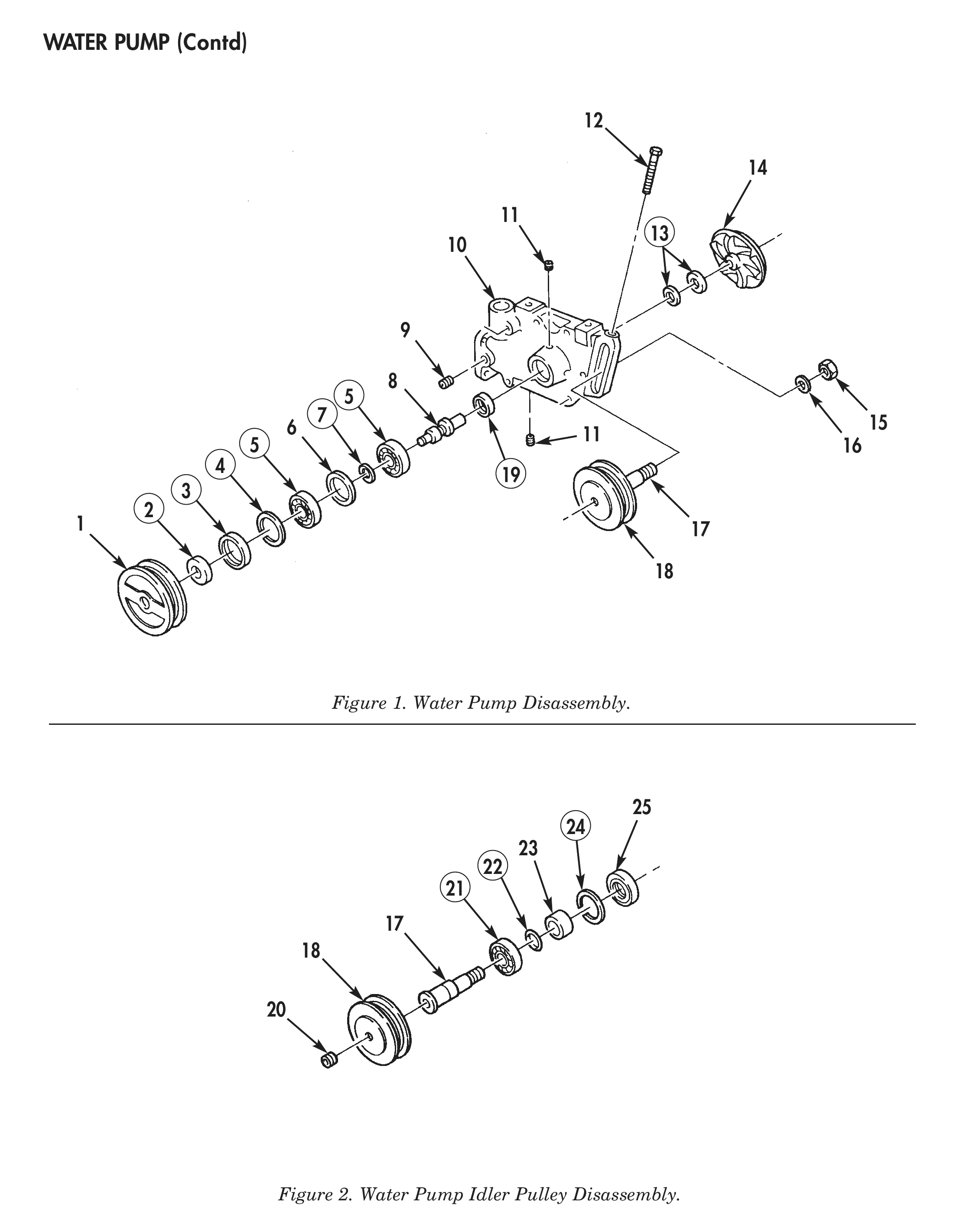
Figure 1. Water Pump Disassembly.
Figure 2. Water Pump Idler Pulley Disassembly.
CLEANING AND INSPECTION
1. For general parts cleaning information, refer to CLEANING, WP 0051 00.
2. For general parts inspection information, refer to INSPECTION, WP 0051 00.
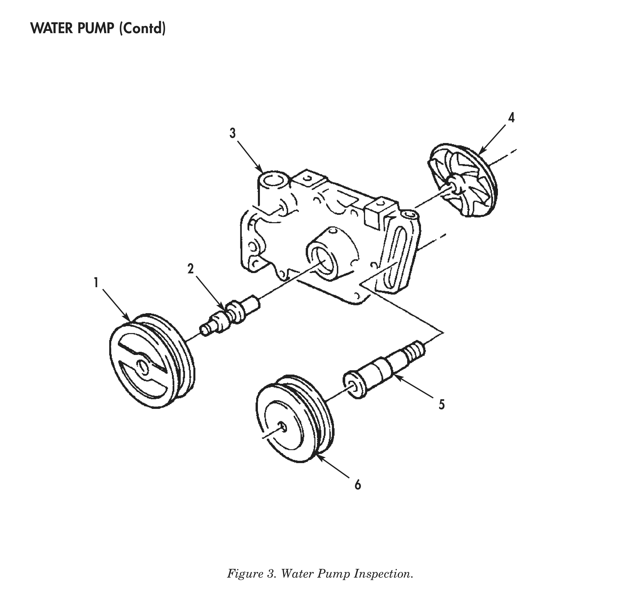
3. Inspect water pump pulley (1) and idler pulley (6) for cracks, chips, or damaged pulley grooves.
4. Inspect water pump housing (3) for cracks, corrosion, and stripped or elongated bolt holes. Repair any stripped holes.
5. Inspect water pump housing (3) weep hole for blockage. Clean weep hole if blocked.
6. Using inside micrometer, measure water pump housing (3) bearing bore. Discard water pump housing (3) if bearing bore is larger than 2.45 in. (62.22 mm).
7. Inspect impeller (4) for cracks, chips, or corrosion.
8. Using micrometer, measure water pump shaft impeller (4) end outside diameter. Diameter should be 0.6262–0.6267 in. (15.905–15.918 mm).
9. Using micrometer, measure water pump shaft (2) pulley end outside diameter. Diameter should be 0.6693–0.6696 in. (17.000–17.008 mm).
10. Using inside micrometer, measure water pump pulley (1) bore inside diameter. Diameter should be 0.6663–0.6673 in. (16.924–16.949 mm).
11. Using inside micrometer, measure impeller (4) bore inside diameter. Diameter should be 0.624–0.625 in. (15.85–15.88 mm).
12. Inspect water pump shaft (2) and idler shaft (5) for cracks, bends, or damaged threads.
ASSEMBLY
1. Using press and water pump bearing mandrel, install new bearing (4) on idler shaft (3) until fully seated.
2. Apply light coat of Loctite to outside diameter of bearing (4). Using press and water pump bearing mandrel, install bearing (4) and idler shaft (3) in idler pulley (2) until fully seated.
3. Install new retaining ring (7), with flat side facing bearing (4), new O-ring (5), and spacer (6) on idler shaft (3).
4. Using oil seal driver, install new seal (8) in idler pulley (2) with seal lip facing idler pulley (2).
5. Apply pipe sealant to pipe plug (1) and install in idler pulley (2).
6. Using oil seal driver, install new sleeve (10) in water pump pulley (9).
7. Apply lubricating oil to new bearing (13). Using press and water pump bearing mandrel, install bearing (13) on water pump shaft (16) until fully seated.
8. Install new retaining ring (15) on water pump shaft (16).
9. Apply lubricating oil to new bearing (13). Using press and water pump bearing mandrel, install spacer (14) and bearing (13) on water pump shaft (16) until fully seated.
10. Using hammer, oil seal driver, and oil seal pilot, install new seal (25) in water pump housing (18).
11. Apply light coat of Loctite to outside diameter of bearings (13). Using press and water pump bearing mandrel, install bearings (13) with water pump shaft (16) attached, in water pump housing (18) until fully seated.
12. Install new retaining ring (12) in water pump housing (18), with flat side of retaining ring (12) facing bearing (13).
13. Using hammer, oil seal driver, and oil seal pilot, install new seal (11), with lip facing bearing (13), in water pump housing (18). Ensure seal (11) is flush with top edge of water pump housing (18) bore.
14. Apply light coat of Loctite to outside diameter of new seal and seat assembly (21), and apply one drop of retaining compound between seal and seat assembly (21). Using press and water pump seal mandrel, install seat and seal assembly (21) in water pump housing (18).
15. Apply pipe sealant to one long pipe plug (17) and two short pipe plugs (19) and install in water pump housing (18).
16. Apply light coat of Loctite to bore of water pump pulley (9). Using press, install water pump pulley (9) on water pump shaft (16) until fully seated.
17. Apply light coat of Loctite to bore of impeller (22). Using press, install impeller (22) on water pump shaft (16) until fully seated.
18. Using feeler gauge, check clearance between impeller (22) and water pump housing (18). Clearance should be 0.020–0.040 in. (0.508–1.016 mm).
19. Install idler pulley (2), with idler shaft (3) attached, on water pump housing (18) with washer (24) and nut (23).
20. Install screw (20) in water pump housing (18).
21. Install water pump (TM 9-2320-273-20 or TM 9-2320-283-20).
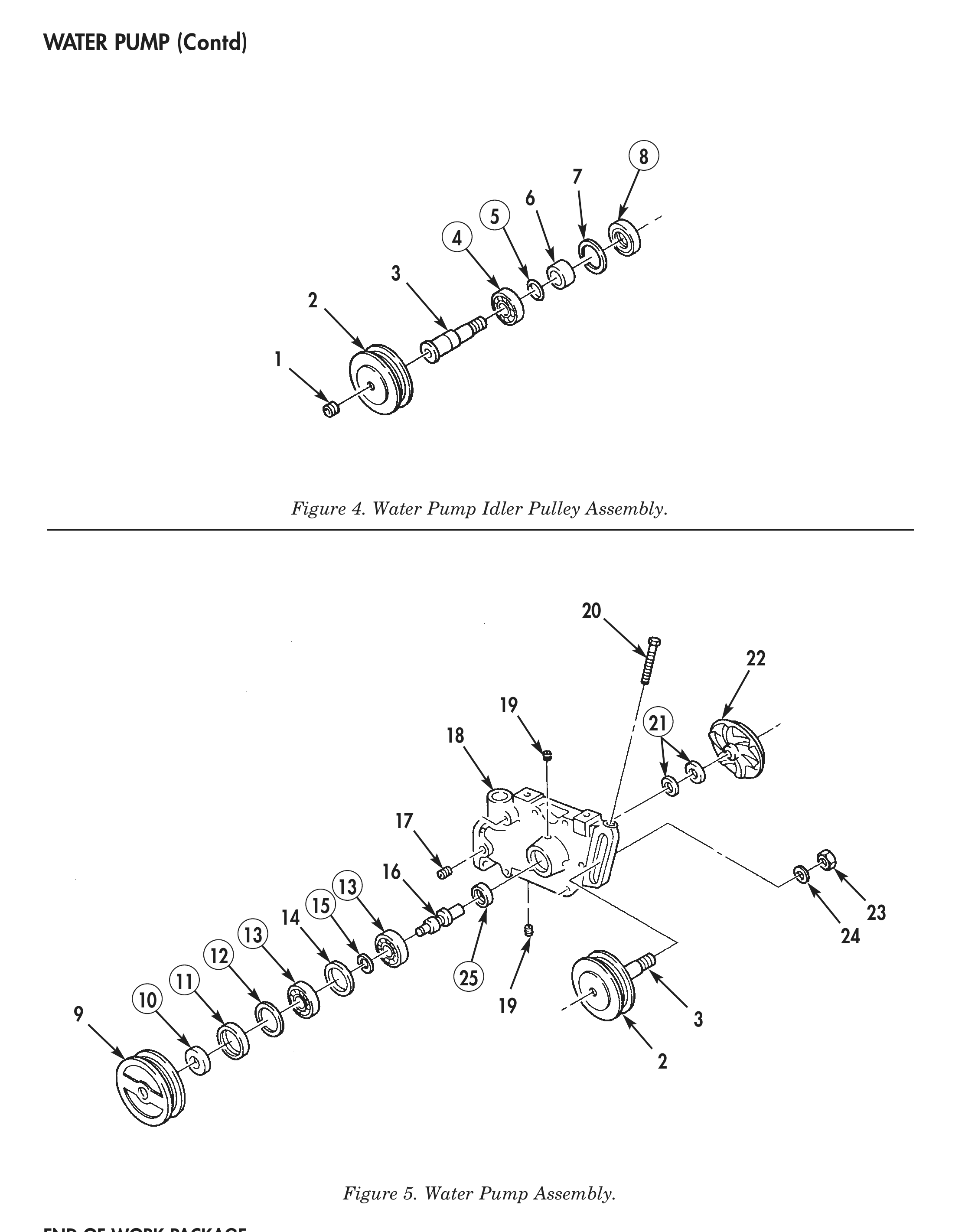
Figure 4. Water Pump Idler Pulley Assembly.
Figure 5. Water Pump Assembly.