CAMSHAFT, CAMSHAFT FOLLOWERS, AND PUSH RODS
TM 9-2815-225-34&P · Work Package 0019 00
DISASSEMBLY, CLEANING AND INSPECTION, ASSEMBLY
INITIAL SETUP
Tools and Special Tools                               Equipment Condition
 General mechanic’s tool kit: automotive               Camshaft, camshaft followers, and push rods
    (Item 1, WP 0061 00)                                 removed from cylinder block (WP 0012 00).
 Maintenance and repair shop equipment:
    automotive (Item 2, WP 0061 00)
 Automotive maintenance and repair
    supplemental set no. 2 (Item 3, WP 0061 00)

Materials/Parts
 240-grit aluminum oxide paper
   (Item 22, WP 0060 00)
 Prussian blue (Item 9, WP 0060 00)
 Thrust bearing (Item 1, Table 4, WP 0062 00)
 Two expansion plugs
   (Item 2, Table 4, WP 0062 00)
DISASSEMBLY
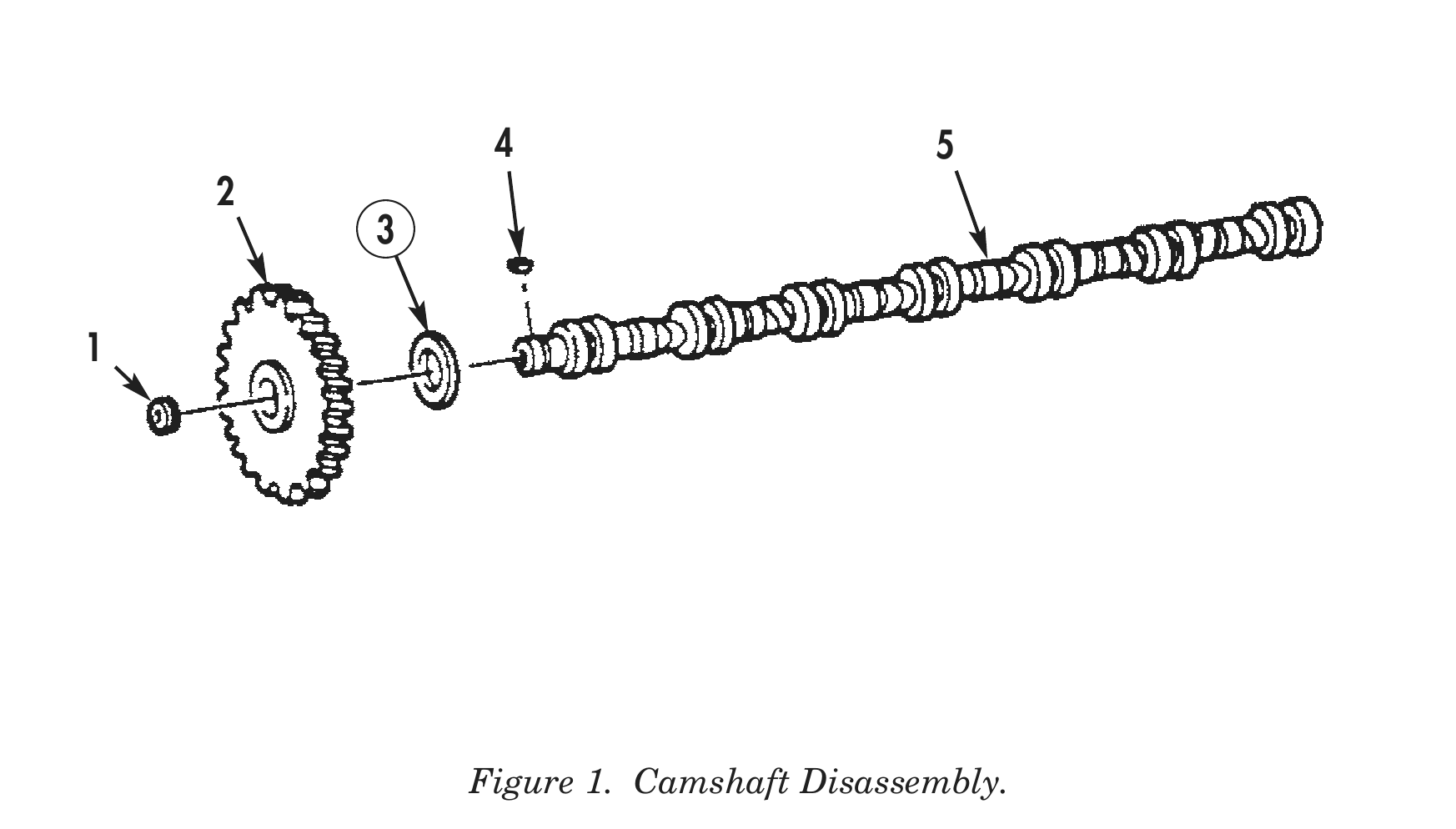
1. Using press, remove camshaft gear (2) and thrust bearing (3) from camshaft (5). Discard thrust bearing (3).
2. Remove keyway (4) and orifice plug (1) from camshaft (5).
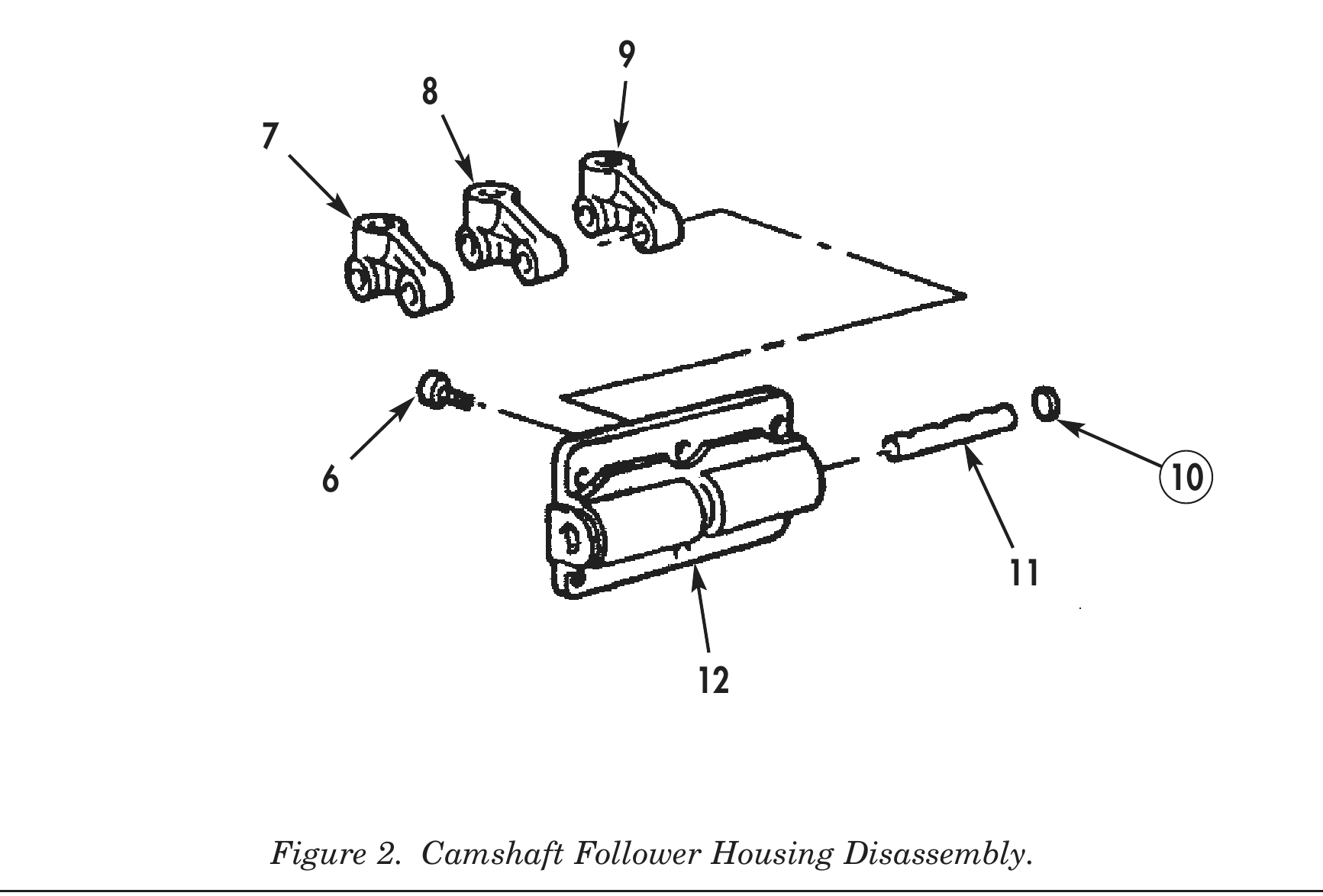
3. Remove two screws (6) retaining camshaft follower shaft (11) in camshaft follower housing (12).
4. Remove two expansion plugs (10) from ends of camshaft follower housing (12). Discard expansion plugs (10).
5. Using press and mandral, remove two camshaft follower shafts (11), intake camshaft followers (7), injector camshaft followers (8), and exhaust camshaft followers (9) from camshaft follower housing (12).
6. Repeat steps 3 through 5 for remaining two camshaft follower housings (12).
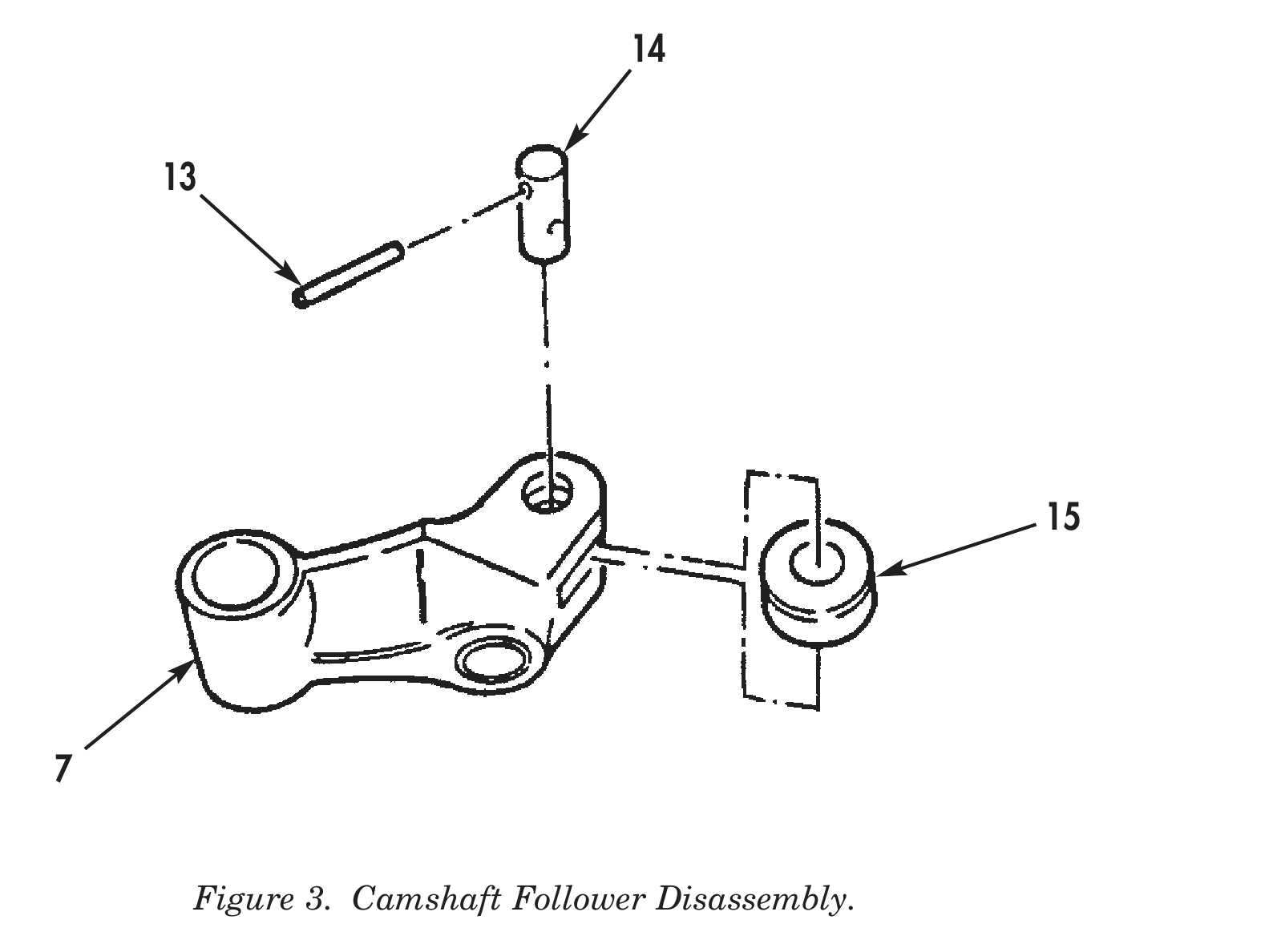
7. Using hammer and drift punch, remove roll pin (13) securing roller pin (14) and roller (15) in intake camshaft follower (7).
8. Remove roller pin (14) and roller (15) from intake camshaft follower lever (7).
9. Repeat steps 7 and 8 for remaining five intake camshaft followers (7), six injector camshaft followers (8), and six exhaust camshaft followers (9).
4 5
CLEANING AND INSPECTION
1. For general parts cleaning information, refer to CLEANING, WP 0051 00.
2. For general parts inspection information, refer to INSPECTION, WP 0051 00.
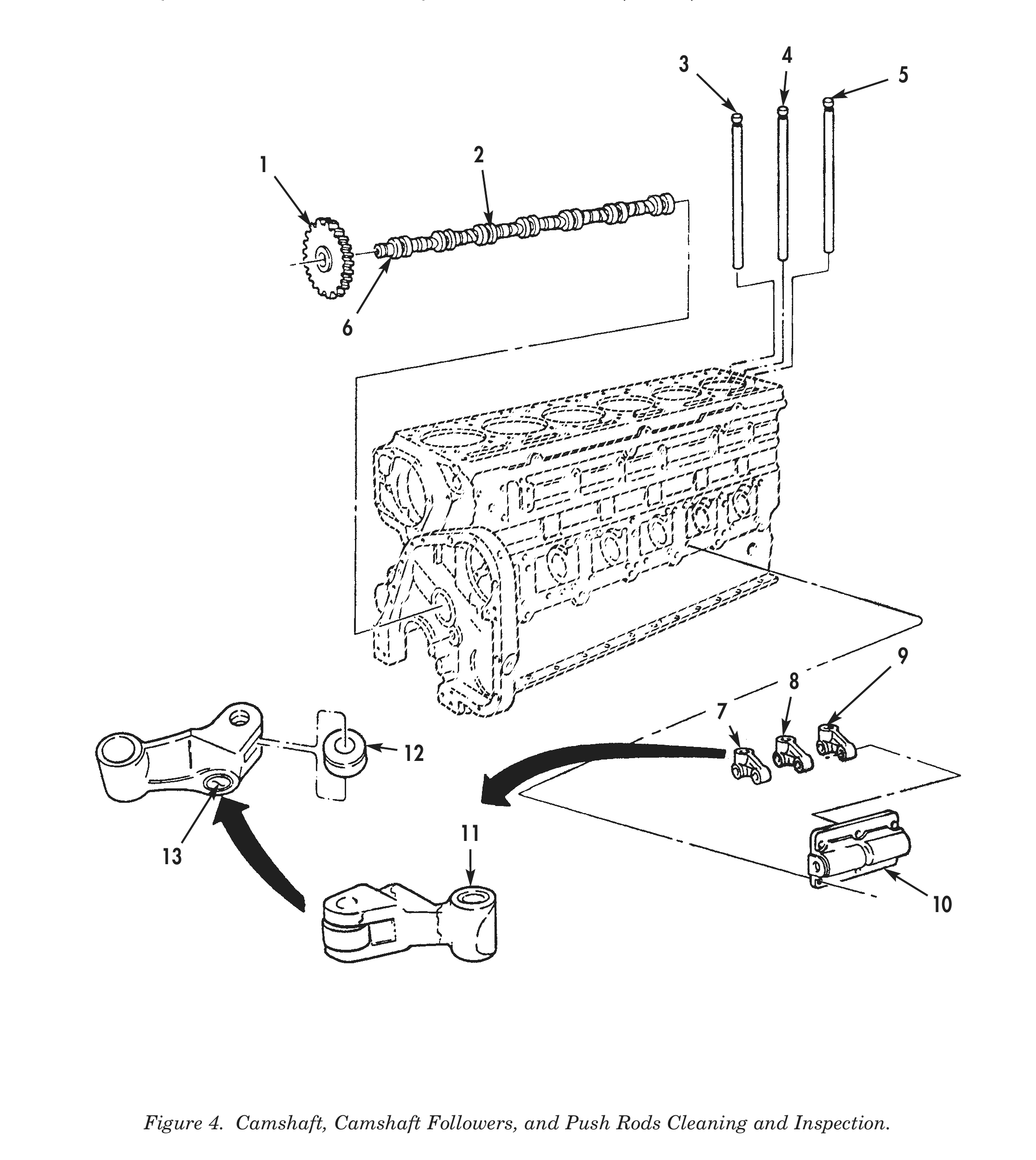
3. Inspect camshaft gear (1) for cracks, chips, rounded or stripped teeth.
4. Using micrometer or equivalent, measure camshaft bearing journals (6) outside diameter. Camshaft bearing journals (6) outside diameter should be 2.496–2.497 in. (6.339–6.342 cm). Discard camshaft (2) if camshaft bearing journals (6) outside diameter is 2.495 in. (6.337 cm) or smaller.
5. Inspect camshaft follower housing (10) for cracks, chips, and breaks.
6. Inspect camshaft follower housing (10) for sharp edges, nicks, or burrs. Camshaft follower housing (10) should have a slight radius. Remove sharp edges, nicks, or burrs with 240-grit aluminum oxide paper attached to a split rod and drill.
7. Inspect cam follower bushing (11) on intake (7), injector (8), and exhaust cam followers (9) for scratches, pitting, scoring and other damage. Discard intake (7), injector (8), and exhaust cam followers (9) if cam follower bushing (11) is damaged.
8. Using micrometer, measure inside diameter of cam follower bushing (11). Discard intake (7), injector (8), or exhaust cam followers (9) if cam follower bushing (11) diameter measures more than 0.752 in. (19.101 mm).
9. Inspect intake (7), injector (8), and exhaust cam follower levers (9) for cracks using magnetic particle inspection (WP 0051 00). Discard intake (7), injector (8), or exhaust cam follower levers (9) if any cracks are found.
10. Inspect pushrod insert (13) for scoring, galling, pitting, and excessive wear.
11. Inspect intake (3), injector (4), and exhaust pushrod (5) for bends or out-of-round. Discard intake (3), injector (4), or exhaust pushrod (5) if bent or out-of-round is more than 0.035 in. (0.889 mm).
12. Check pushrod insert (13) using ball end of intake (3), injector (4), and exhaust pushrods (5) as follows:
a. Apply a coat of Prussian blue compound to ball end of intake (3), injector (4), and exhaust pushrods (5).
b. Install ball end of intake (3), injector (4), and exhaust pushrods (5) into pushrod insert (13) and rotate 80°.
c. Replace intake (7), injector (8), and exhaust cam followers (9) if pushrod insert (13) is damaged or has less than 80% contact with ball end of intake (3), injector (4), and exhaust pushrods (5).
13. Inspect roller (12) for cracks, breaks, and other damage. Discard intake (7), injector (8), or exhaust cam followers (9) if roller (12) is damaged.
14. Using small bore gauge, measure roller (12) inside diameter.
CLEANING AND INSPECTION (Contd)
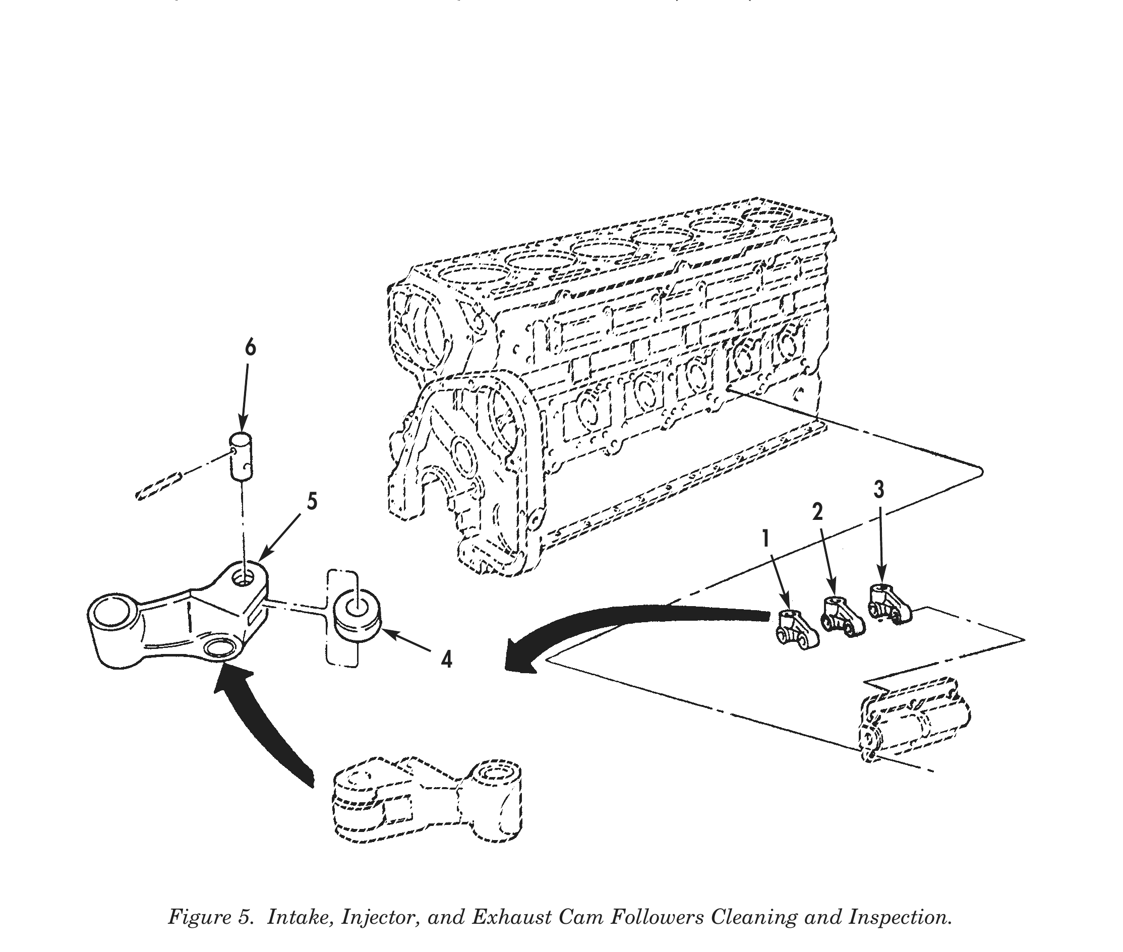
15. Inspect roller (4) to ensure it is not out-of-round. Discard intake (1), injector (2), or exhaust cam follower (3) if roller (4) is out-of-round.
16. Using micrometer, measure roller (4) outside diameter. Discard intake (1), exhaust (3) or injector cam followers (2) if outside diameter measures less than 1.2485 in. (31.712 mm).
17. Check concentricity of inside diameter with outside diameter of intake (1), injector (2), and exhaust cam followers (3). Discard intake (1), injector (2), or exhaust cam followers (3) if concentricity of inside diameter with outside diameter is not within 0.0020 in. (0.051 mm).
18. Check intake (1), injector (2), and exhaust cam follower (3) squareness of sides with roller pin bore. Discard intake (1), injector (2), and exhaust cam followers (3) if sides are not parallel to each other or not square to bore within 0.0040 in. (0.102 mm).
19. Inspect roller pin (6) for cracks, breaks, and other damage. Discard intake (1), injector (2), and exhaust cam followers (3) if roller pin (6) is damaged.
20. Using micrometer, measure outside diameter of roller pin (6).
a. Discard intake (1) or exhaust cam followers (3) if outside diameter measures less than 0.497 in. (12.624 mm).
b. Discard injector cam follower (2) if outside diameter measures less than 0.697 in. (17.704 mm).
21. Using micrometer, measure roller pin bore (5).
a. Discard intake (1) or exhaust cam followers (3) if roller pin bore (5) is not within 0.4990–0.4995 in. (12.675–12.687 mm).
b. Discard injector cam follower (2) if roller pin bore (5) is not within 0.6992–0.6997 in. (17.760–17.772 mm).
ASSEMBLY
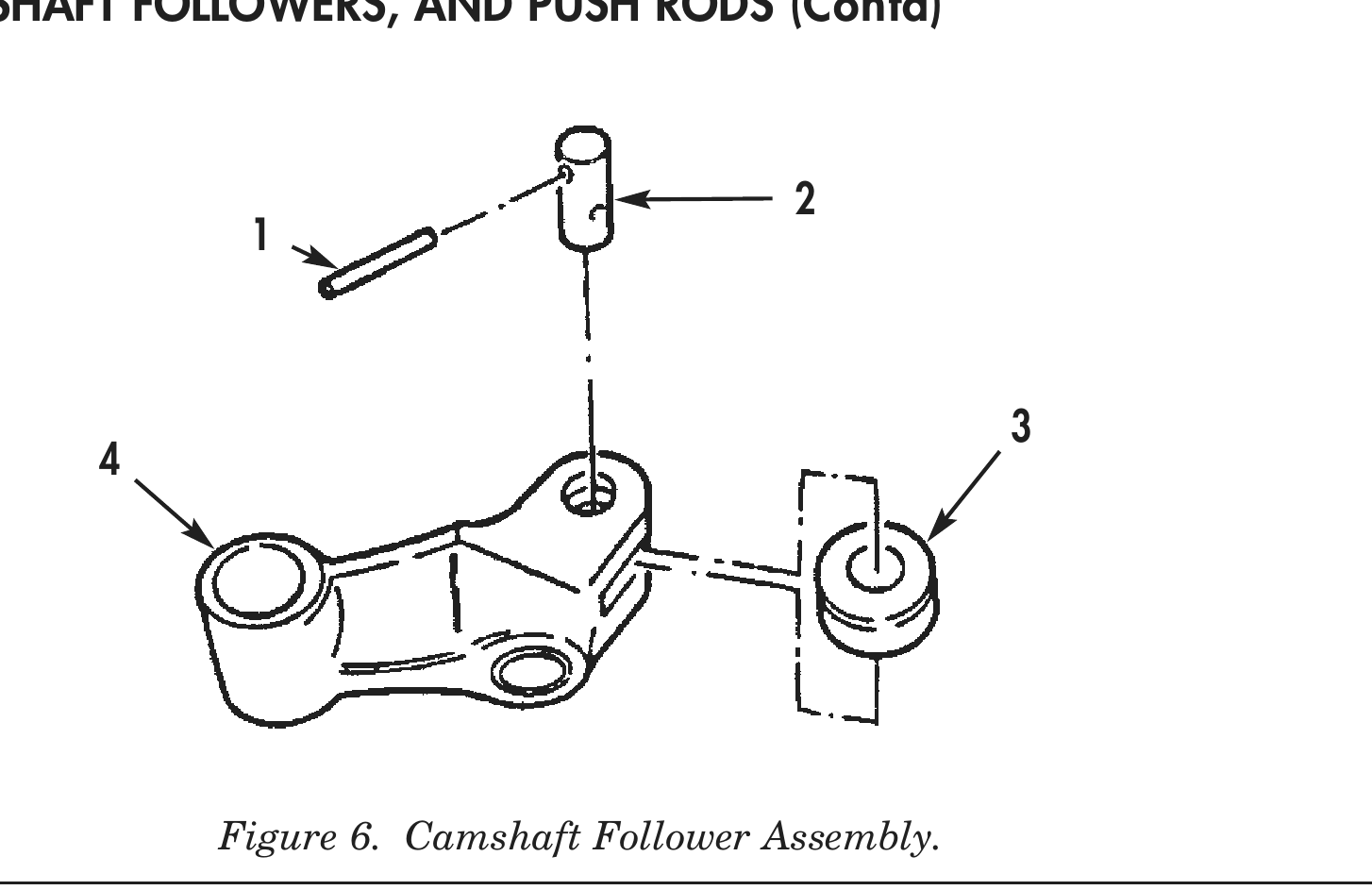
1. Install roller pin (2) and roller (3) on intake cam follower (4).
2. Using 0.006 in. (0.15 mm) feeler gauge between intake cam follower (4) and roller (3), install roller pin (2) on intake cam follower (4) and roller (3). Secure roller pin (2) to intake cam follower (4) with roll pin (1).
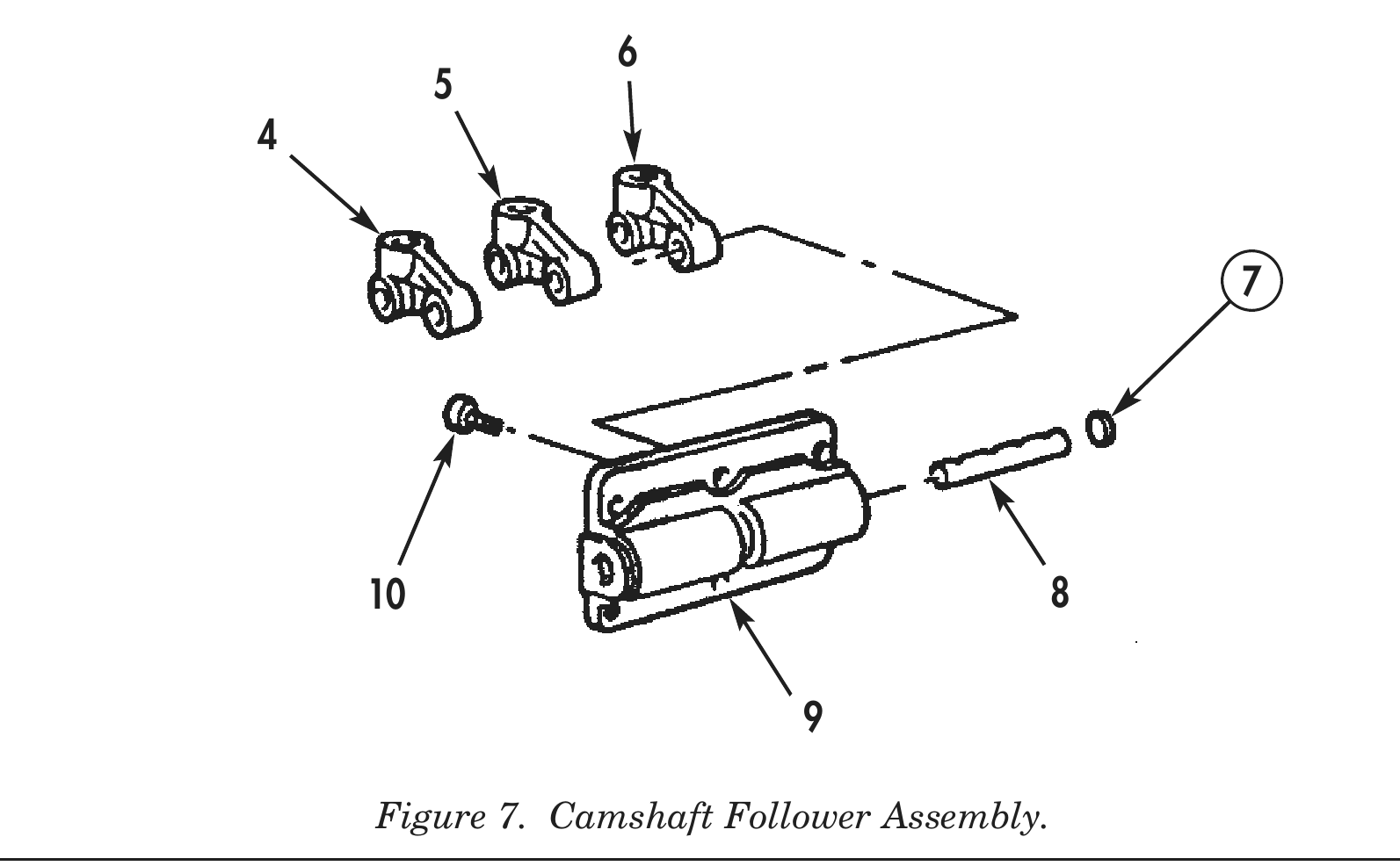
3. Install two exhaust camshaft followers (6), injector camshaft followers (5), intake camshaft followers (4), and camshaft follower shafts (8) on camshaft follower housing (9).
4. Using press and mandrel, install two new expansion plugs (7) on ends of camshaft follower housing (9).
5. Install two screws (10) securing camshaft follower shaft (8) on camshaft follower housing (9).
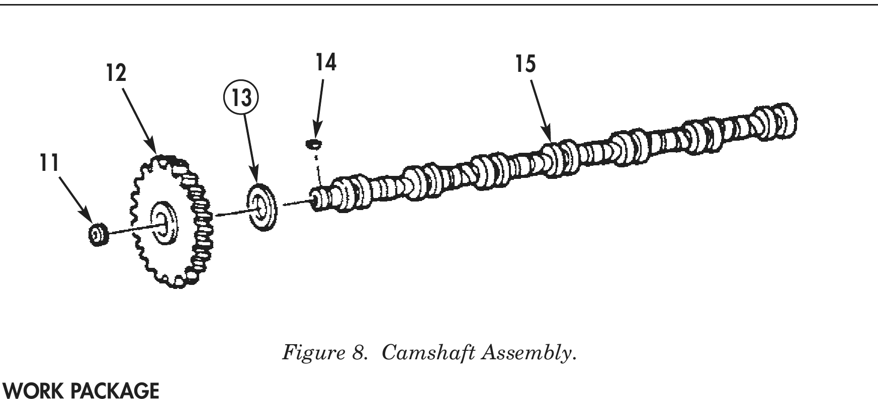
6. Install orifice plug (11) and keyway (14) on camshaft (15). Tighten orifice plug (11) 5–10 lb-ft (7–13 N•m).
7. Heat camshaft gear (12) evenly in oven to 400º F (209° C).
8. Using press, install hot camshaft gear (12), new thrust bearing (13), and keyway (14) on camshaft (15).