BIG CAM III MODIFICATION KIT INSTALLATION INSTRUCTIONS
TM 9-2815-225-34&P · Work Package 0050 00
INITIAL SETUP
Tools and Special Tools
 General mechanic’s tool kit: automotive
    (Item 1, WP 0061 00)
 Maintenance and repair shop equipment,
    automotive (Item 2, WP 0061 00)
 Automotive maintenance and repair
    supplemental set no. 2 (Item 3, WP 0061 00)

Personnel Required
 Assistant
GENERAL INFORMATION

                                                    NOTE
                        The following guidelines apply for using the Big Cam III
                        engines in other than M915A1 vehicles.
 1.   Installing the Big Cam III requires that you retain and use the following components from the
      BIG Cam I:
      •     Big Cam I flywheel housing
      •     Big Cam I flywheel
      •     Big Cam I lower alternator bracket
                                                    NOTE
                        It is recommended that you retain the Big Cam I engine for use
                        of other miscellaneous parts.
 2.   Refer to table 1 for parts which are required to complete the conversion.

                             Table 1. Parts Required for Big Cam III Coversion.

             NAME                   PART NUMBER         NATIONAL STOCK NUMBER            QUANTITY

           Seal ring                  2D6507               5330-01-066-4537                 1
             Seal                     5P3881               5330-01-079-4737                 1
           Pipe plug                  144027               4730-00-014-4027                 2
           Pipe plug                  444632               4730-00-044-4632                 1
          Plug button                 142083               5340-00-290-4532                 1
ENGINE PREPARATION
1. Remove alternator, alternator drive belt, and alternator mounting bracket from Big Cam III engine (2). Refer to WP 0008.
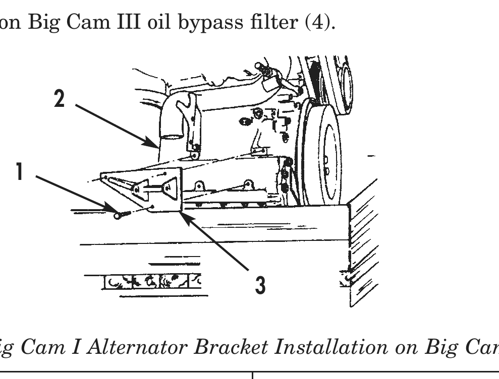
2. Install Big Cam I alternator mounting bracket (3) on Big Cam III engine (2) with three bolts (1). Tighten bolts (1).
3. Install Big Cam I alternator and drive belt on Big Cam III engine. Refer to WP 0049.
4. Remove exisiting Big Cam I engine from vehicle. Refer to WP 0007.
BIG CAM III INSTALLATION PROCEDURES
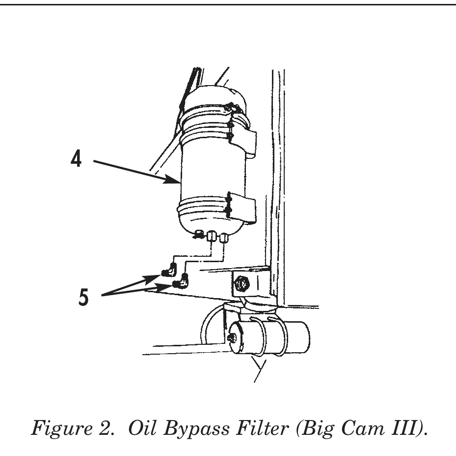
1. Drain oil from Big Cam III bypass filter (4) and remove oil bypass filter element from bypass filter (4).
2. Remove two elbows (5) from oil bypass filter (4).
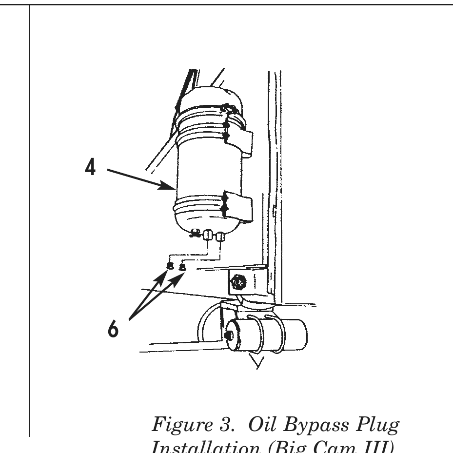
3. Install two plugs (6) on Big Cam III oil bypass filter (4).
Figure 1. Big Cam I Alternator Bracket Installation on Big Cam III Engine.
4 4
Figure 3. Oil Bypass Plug Installation (Big Cam III).
BIG CAM III INSTALLATION PROCEDURES (Contd)
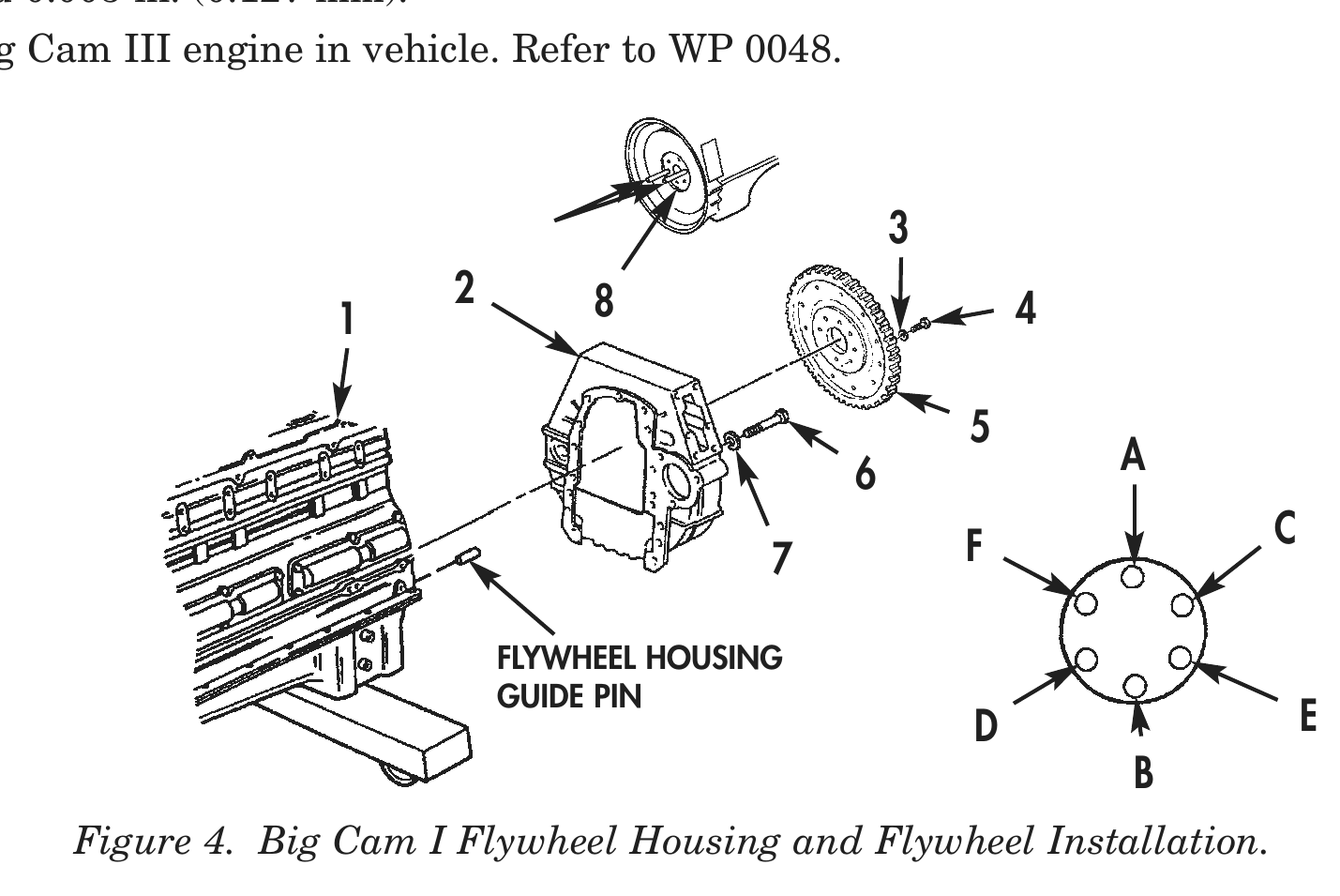
4. Install two flywheel housing guide pins on Big Cam III engine (1).
5. Install Big Cam I flywheel housing (2) on Big Cam III engine (1) with seven of nine screws (6) and washers (7). Tighten screws (6) 10–20 lb-ft (14–27 N•m).
6. Remove two flywheel housing guide pins from Big Cam III engine (1) and install two remaining screws (6) and washers (7) on Big Cam I flywheel housing (2). Tighten screws (6) 10–20 lb-ft (14–27 N•m).
7. Install two 5/8–18x6 in. guide studs in opposite holes on Big Cam III crankshaft (8) until fully seated.
8. Apply lubricating oil to threads of screws (4) and face of washers (3). Allow excess oil to drain from screw threads.
9. Install Big Cam I flywheel (5) on Big Cam III crankshaft (8) with four screws (4) and washers (3). Tighten screws (4) hand-tight in sequence shown in figure 4.
10. Remove two guide studs and install two remaining screws (4) and washers (3) on Big Cam I flywheel (5). Tighten screws (4) 70 lb-ft (95 N•m) then 140 lb-ft (190 N•m) and finally 200–220 lb- ft (271–298 N•m) in sequence shown in figure 4.
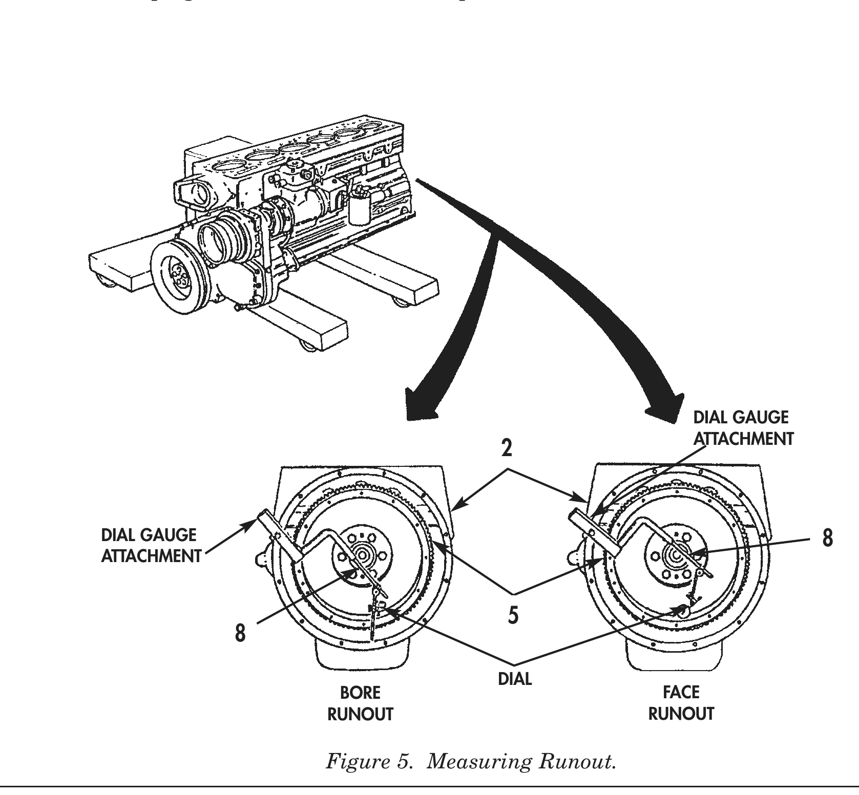
11. Install dial gauge attachment and dial indicator on Big Cam I flywheel housing (2).
12. Position contact tip of dial indicator against wide diameter of Big Cam I flywheel (5) bore and set dial indicator to zero. Rotate crankshaft (8) one complete revolution. Total indicator reading must not exceed 0.005 in. (0.127 mm).
13. Inspect Big Cam I flywheel (5) face runout and install or reposition dial indicator on Big Cam I flywheel housing (2).
14. Position contact tip of dial indicator against face of Big Cam I flywheel (5) as close to outside diameter as possible. Rotate crankshaft (8) one complete revolution. Total indicator reading must not exceed 0.005 in. (0.127 mm).
15. Install Big Cam III engine in vehicle. Refer to WP 0048.
2 8 4
6               A
F              C
FLYWHEEL HOUSING
GUIDE PIN
D                  E
B Figure 4. Big Cam I Flywheel Housing and Flywheel Installation.
BIG CAM III INSTALLATION PROCEDURES (Contd)
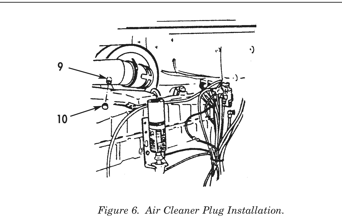
16. Install button plug (10) on air cleaner intake port (9).
DIAL GAUGE
ATTACHMENT
DIAL GAUGE                                                                 8
ATTACHMENT
DIAL
BORE                            FACE
RUNOUT                          RUNOUT
END OF WORK PACKAGE