AIR AFTERCOOLER
TM 9-2815-225-34&P · Work Package 0024 00
DISASSEMBLY, CLEANING AND INSPECTION, ASSEMBLY
INITIAL SETUP
Tools and Special Tools                               Equipment Condition
 General mechanic’s tool kit:                          Air aftercooler removed from engine
    automotive (Item 1, WP 0061 00)                      (WP 0010 00).
 Maintenance and repair shop equipment:
    automotive (Item 2, WP 0061 00)
 Automotive maintenance and repair
    supplemental set no. 2 (Item 3, WP 0061 00)
 Air pressure tester (Item 4, WP 0061 00)

Materials/Parts
 OE/HDO 10 lubricating oil
   (Item 19, WP 0060 00)
 Gasket (Item 1, Table 8, WP 0062 00)
 Gasket (Item 2, Table 8, WP 0062 00)
 Gasket (Item 3, Table 8, WP 0062 00)
 Four O-rings (Item 4, Table 8, WP 0062 00)
DISASSEMBLY
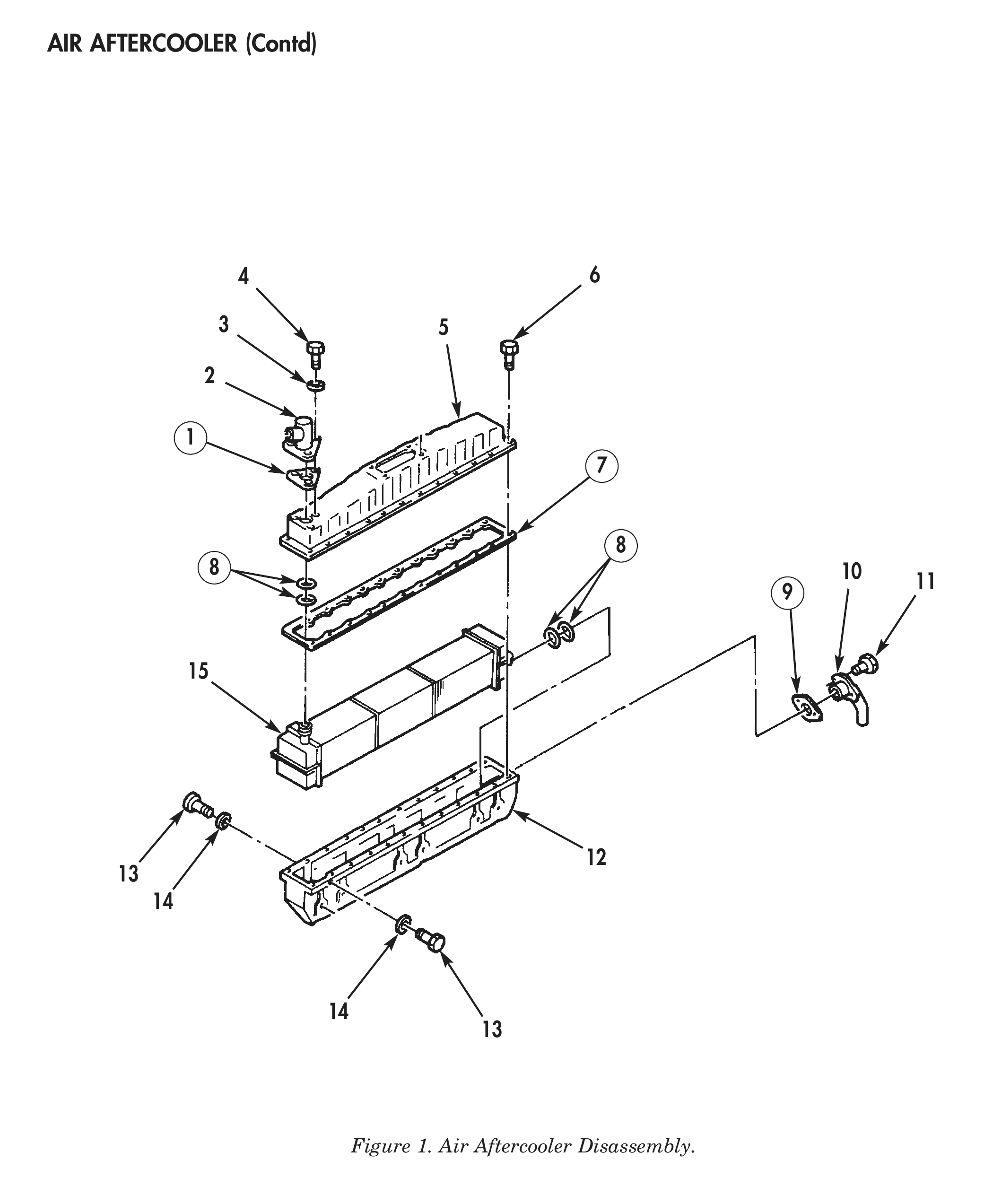
1. Remove three screws (4), washers (3), water outlet (2), and gasket (1) from air aftercooler cover (5). Discard gasket (1).
2. Remove two screws (11), water inlet (10), and gasket (9) from intake manifold (12). Discard gasket (9).
3. Remove twenty-four screws (6), air aftercooler cover (5), and gasket (7) from intake manifold (12). Discard gasket (7).
4. Remove eight screws (13), washers (14), and air aftercooler element (15) from intake manifold (12).
5. Remove four O-rings (8) from air aftercooler element (15). Discard O-rings (8).
CLEANING AND INSPECTION
1. For general parts cleaning information, refer to CLEANING, WP 0051 00.
2. For general parts inspection information, refer to INSPECTION, WP 0051 00.
3. Inspect water outlet (2), water inlet (10), air aftercooler cover (5), and intake manifold (12) for cracks, corrosion, and stripped or elongated threaded holes. Repair any damaged threaded holes.
4. Inspect air aftercooler element (15) for cracks, corrosion, and stripped or elongated threaded holes. Repair any damaged threaded holes.
5. Inspect air aftercooler element (15) for leaks, as follows:
a. Cap one end of air aftercooler element (15) airtight.
b. Connect a suitable air pressure tester to other end of air aftercooler element (15).
c. Immerse air aftercooler element (15) in tank of water, pressurize air aftercooler element (15) to 20 psi (138 kPA) for 2 minutes, and look for bubbles.
d. If a leak is detected, replace air aftercooler element (15).
ASSEMBLY
1. Apply OE/HDO 10 lubricating oil to four new O-rings (8) and install O-rings on air aftercooler element (15).
2. Install air aftercooler element (15) in intake manifold (12).
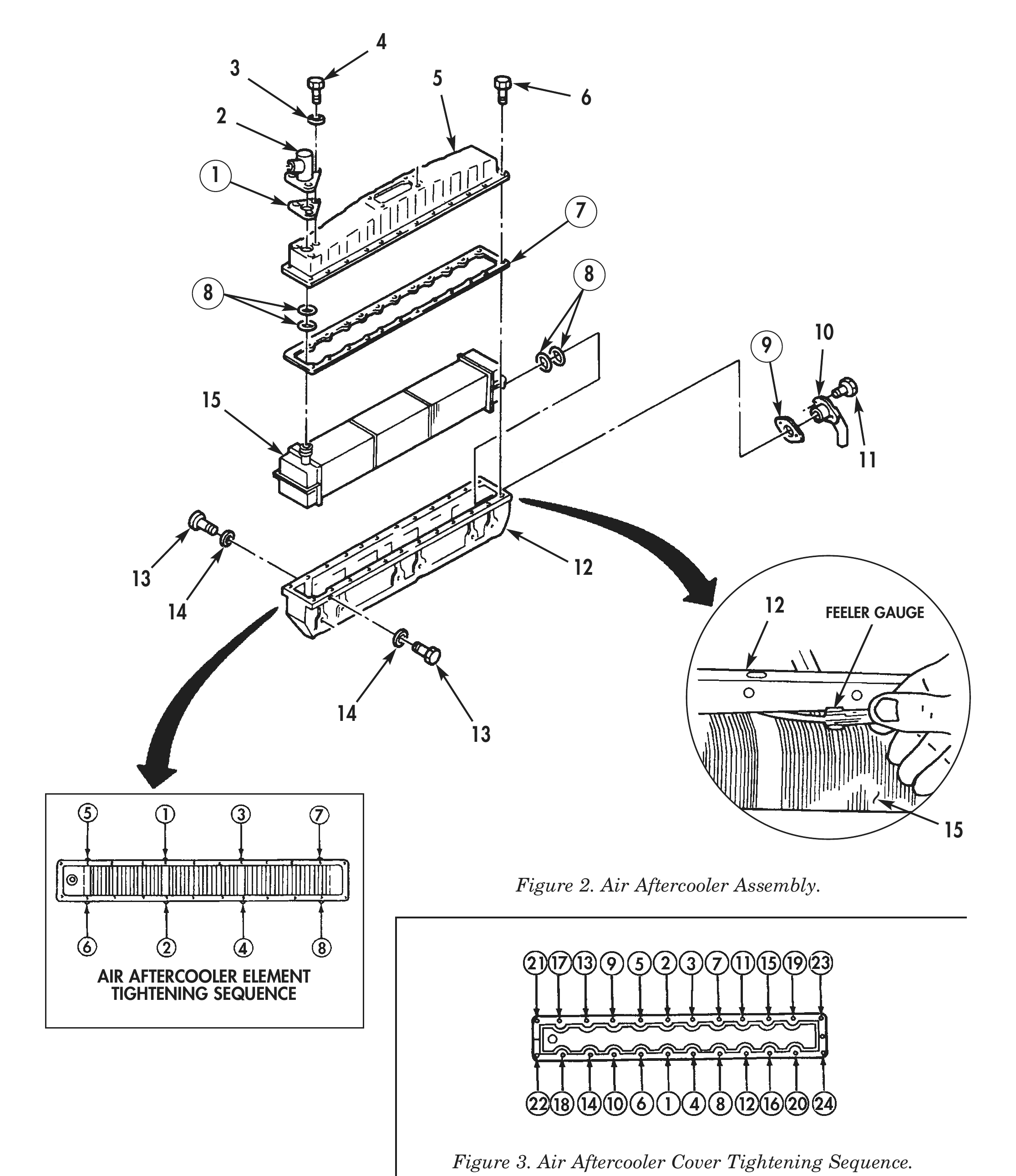
3. Hold air aftercooler element (15) to one side of intake manifold (12). Using feeler gauge, measure clearance between air aftercooler element (15) and intake manifold (12). Clearance must be 0.003–0.013in. (0.076–0.330 mm).
4. Align holes in intake manifold (12) with holes in air aftercooler element (15). Install air aftercooler element (15) in intake manifold (12) with eight washers (14) and screws (13). Tighten air aftercooler element screws (13) in sequence 15 lb-ft (20 N•m).
5. Tighten air aftercooler element screws (13) in sequence again 25 lb-ft (34 N•m).
6. Install new gasket (7) and air aftercooler cover (5) on intake manifold (12) with twenty-four screws (6). Do not tighten screws (6) at this time.
7. Install new gasket (9) and water inlet (10) on intake manifold (12) with two screws (11). Tighten screws (11) 32 lb-ft (43 N•m).
8. Install new gasket (1) and water outlet (2) on air aftercooler cover (5) with three washers (3) and screws (4). Do not tighten screws (4) at this time.
9. Tighten twenty-four screws (6) securing air aftercooler cover (5) to intake manifold (12) in sequence shown 25 lb-ft (34 N•m).
10. Tighten three screws (4) securing water outlet (2) to air aftercooler cover (5) 20 lb-ft (27 N•m).
11. For air aftercooler installation, refer to WP 0045 00.
3 5
14 12 FEELER GAUGE
AIR AFTERCOOLER ELEMENT
TIGHTENING SEQUENCE
Figure 3. Air Aftercooler Cover Tightening Sequence.
END OF WORK PACKAGE