CYLINDER HEAD
TM 9-2815-225-34&P · Work Package 0014 00
DISASSEMBLY, CLEANING AND INSPECTION, ASSEMBLY
INITIAL SETUP
Tools and Special Tools                              Materials/Parts (Contd)
 General mechanic’s tool kit: automotive              Twelve exhaust valves
    (Item 1, WP 0061 00)                                (Item 8, Table 2, WP 0062 00)
 Maintenance and repair shop equipment:               Expansion plug
    automotive (Item 2, WP 0061 00)                     (Item 9, Table 2, WP 0062 00)
 Automotive maintenance and repair                    Two expansion plugs
    supplemental set no. 2 (Item 3, WP 0061 00)         (Item 10, Table 2, WP 0062 00)
 Valve spring compressor                              Twenty-four valve stem guides
    (Item 53, WP 0061 00)                               (Item 11, Table 2, WP 0062 00)
 Valve seat extractor (Item 54, WP 0061 00)           Locknut (Item 12, Table 2, WP 0062 00)
 Expansion plug driver (Item 55, WP 0061 00)          Twelve O-rings (Item 13, Table 2, WP 0062 00)
 Valve vacuum tester (Item 56, WP 0061 00)
                                                     Equipment Condition
Materials/Parts                                       Engine crankshaft and main bearings removed
 Lubricating oil (Item 19, WP 0060 00)                  (WP 0012 00).
 Liquid thread sealant (Item 26, WP 0060 00)
 Twenty-four valve spring retainers
   (Item 1, Table 2, WP 0062 00)
 Twenty-four valve springs
   (Item 2, Table 2, WP 0062 00)
 Twenty-four valve spring retainers
   (Item 3, Table 2, WP 0062 00)
 Six injector O-rings
   (Item 4, Table 2, WP 0062 00)
 Six expansion plugs
   (Item 5, Table 2, WP 0062 00)
 Twenty-four valve seat inserts
   (Item 6, Table 2, WP 0062 00)
 Twelve intake valves
   (Item 7, Table 2, WP 0062 00)
DISASSEMBLY
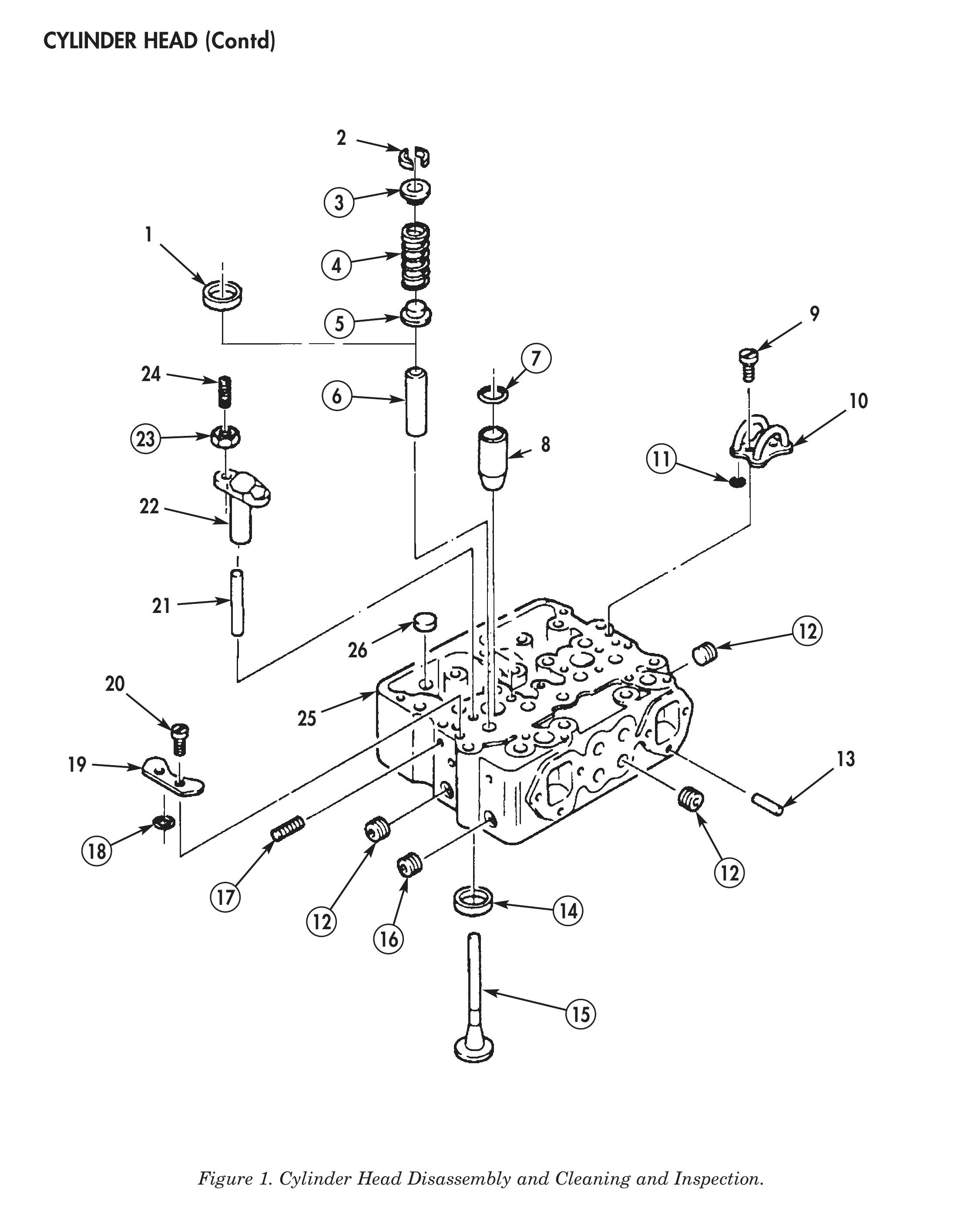
1. Remove locknut (23) and adjusting screw (24) from exhaust valve crosshead (22). Discard locknut (23).
2. Remove exhaust valve crosshead (22) and crosshead guide (21) from cylinder head (25).
3. Using valve spring compressor, compress exhaust valve spring (4).
4. Remove two valve collets (2) from exhaust valve (15).
5. Remove exhaust valve (15), spring retainer (3), valve spring (4), and spacer (5), if used, from cylinder head (25). Discard exhaust valve (15), valve spring (4), retainer (3), and spacer (5).
6. Remove valve stem guide (6) from cylinder head (25). Discard valve stem guide (6).
7. Using valve seat extractor, remove valve seat insert (14) from cylinder head (25). Discard valve seat insert (14).
8. Perform steps 1 through 7 for remaining exhaust and intake valves.
9. Using injector sleeve puller, remove two injector sleeves (8) and injector O-rings (7) from cylinder head (25). Discard injector O-rings (7).
10. Remove two screws (20), cover plate (19), and two O-rings (18) from cylinder head (25). Discard O-rings (18).
11. Remove four pipe plugs (17) from cylinder head (25).
12. Using hammer and punch, tap outside diameter of expansion plugs (12) and (16) to force one side out from cylinder head (25).
13. Using screwdriver, remove six expansion plugs (12), plug (16), and two plugs (26) from cylinder head (25). Discard expansion plugs (12), (16), and (26).
14. Remove four screws (9), two fuel connections (10), and four O-rings (11) from cylinder head (25). Discard O-rings (11).
15. Remove two dowels (13) from cylinder head (25).
16. Perform steps 1 through 15 for remaining cylinder heads (25).
CLEANING AND INSPECTION
1. For general parts cleaning information, refer to CLEANING, WP 0051 00.
2. For general parts inspection information, refer to INSPECTION, WP 0051 00.
3. Inspect cylinder head (25) for cracks, breaks, distortion, and broken-out areas.
4. Using straightedge and feeler gauge, inspect cylinder head (25) for distortion on mating surface. Maximum distortion is 0.002 in. (0.051 mm).
CLEANING AND INSPECTION (Contd)
5. Using vernier depth gauge, measure cylinder head (25) height. Minimum cylinder head height is 4.30 in. (11.024 cm).
6. Inspect injector sleeves (8) for scratches and cracks.
7. Inspect all parts for cracking, breaking, excessive wear, or other damage.
8. Inspect all threaded parts for stripped threads or cross-threading.
ASSEMBLY
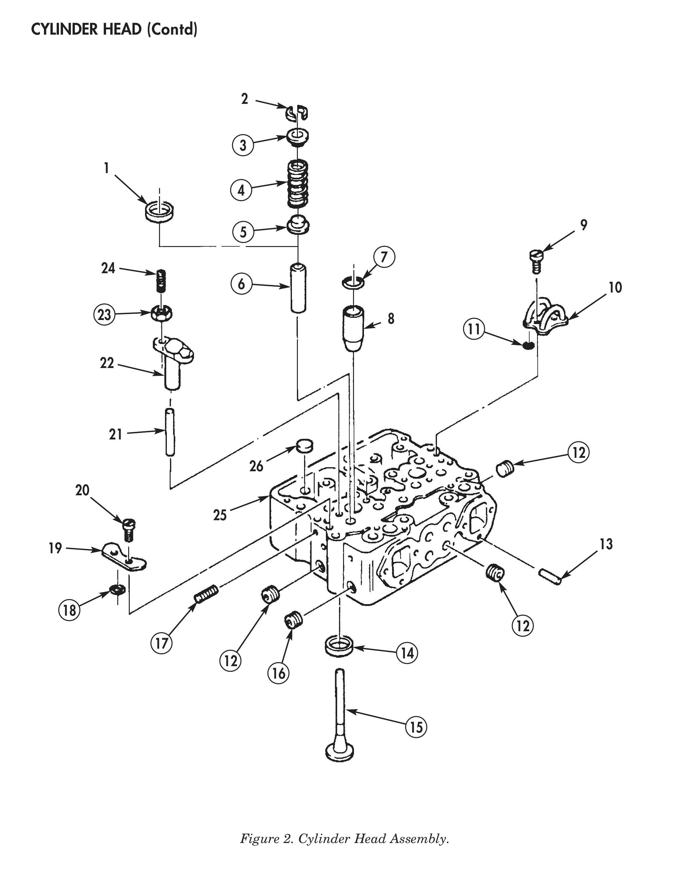
1. Apply cup plug sealant to six new expansion plugs (12), new plug (16), and two new plugs (26), and to inside diameter of water holes on cylinder head (25).
2. Using expansion plug driver, install expansion plugs (12), (16), and (26) on cylinder head (25).
3. Apply clean lubricating oil to two new O-rings (18). Install cover plate (19) and O-rings (18) on cylinder head (25) with two screws (20).
4. Using valve seat inserter, install new valve seat insert (14) on cylinder head (25).
5. Using valve stem guide driver, install new valve stem guide (6) on cylinder head (25).
6. Apply clean lubricating oil to new exhaust valve (15) and install exhaust valve (15) on new valve stem guide (6) from bottom side of cylinder head (25).
7. Place cylinder head (25) on protective surface with machined surface down.
8. Install new spacer (5), if necessary, new valve spring (4), and new retainer (3) over valve stem guide (6) on cylinder head (25).
9. Using valve spring compressor, compress valve spring (4) and install valve collet (2) on stem of valve (15).
10. Using valve vacuum tester, check seal between valve (15) and valve seat (14).
11. Install two adjusting screws (24) and new locknuts (23) on exhaust valve crosshead (22).
12. Install exhaust valve crosshead (22) and crosshead guide (21) on cylinder head (25).
13. Perform steps 4 through 12 for remaining intake and exhaust valves.
14. Apply clean lubricating oil to new O-ring (11). Install screw (9), fuel connection (10), and O-ring (11) on cylinder head (25).
15. Apply clean lubricating oil to new O-rings (7). Using injector sleeve driver, install injector sleeve (8) and injector O-ring (7) on cylinder head (25).
16. Apply clean lubricating oil to eleven dowels (13), and install eleven dowels (13) on cylinder head (25).
17. Apply liquid thread sealant to four pipe plugs (17), and install pipe plugs (17) on cylinder head (25).
                                                      NOTE
                                      Step 18 is for Big Cam I engines only.
18.   Tighten pipe plugs (17) as shown in table 1.
19.   Perform steps 1 through 18 for remaining cylinder heads (25).

                                    Table 1. Pipe Plugs Torque Specifications.
              PIPE PLUG SIZE                         MINIMUM                             MAXIMUM

      INCH                 (MM)              LB FT               (N•m)           LB FT             (N•m)
       3/16                9.525               35                 47              45                61
       1/2                 12.70               60                 81              70                95
       3/4                     19              65                 88              75                102
        1                      25             135                 183             145               197

END OF WORK PACKAGE