CYLINDER HEAD AND CYLINDER HEAD COMPONENTS INSTALLATION
TM 9-2815-225-34&P · Work Package 0043 00
CYLINDER HEAD, FUEL INJECTOR, ROCKER ARM HOUSING, ENGINE BRAKE RETARDER, ROCKER COVER
INITIAL SETUP
Tools and Special Tools                             Equipment Condition
 General mechanic’s tool kit: automotive             Engine mounted on maintenance stand
    (Item 1, WP 0061 00)                               (WP 0009 00).
 Maintenance and repair shop equipment:
    automotive (Item 2, WP 0061 00)
 Automotive maintenance and repair
    supplemental set no. 2 (Item 3, WP 0061 00)
 Fuel injector puller (Item 8, WP 0061 00)

Material/Parts
 Twelve O-rings (Item 1, Table 26, WP 0062 00)
 Three cylinder head gaskets
   (Item 2, Table 26, WP 0062 00)
 Three gaskets (Item 3, Table 26, WP 0062 00)
 Three gaskets (Item 4, Table 26, WP 0062 00)
 Three gaskets (Item 5, Table 26, WP 0062 00)
 Eighteen O-rings
   (Item 6, Table 26, WP 0062 00)
 Rust preventative lubricant
   (Item 16, WP 0060 00)
 OE/HDO 10 lubricating oil
   (Item 19, WP 0060 00)
 60-80/140 lubricating oil
   (Item 21, WP 0060 00)
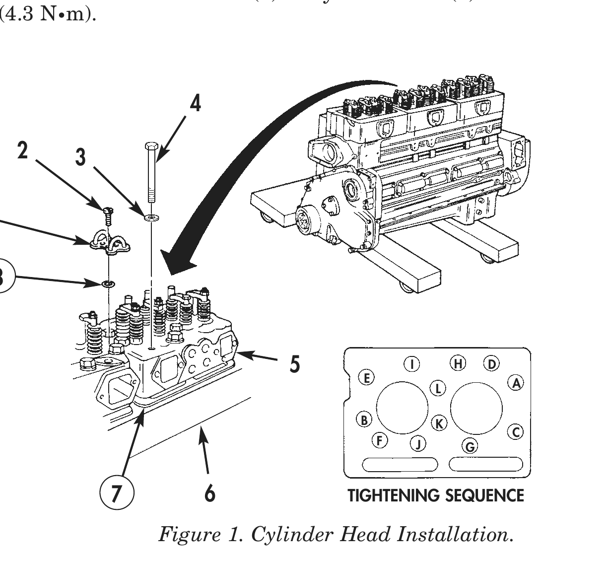
CYLINDER HEAD
1. Install new cylinder head gasket (7) on cylinder head (5).
2. Install cylinder head (5) on cylinder block (6).
3. Apply rust preventative lubricant to twelve screws (4). Allow excess lubricant to drip from screw threads before installation.
4. Install twelve screws (4) and washers (3) on cylinder head (5). Tighten screws (4) 25 lb-ft (34 N•m) in sequence shown in figure 1.
5. Tighten screws (4) 100 lb-ft (136 N•m) in sequence shown in figure 1.
6. Tighten screws (4) 305 lb-ft (414 N•m) in sequence shown in figure 1.
7. Tighten screws (4) 285 lb-ft (387 N•m) in sequence shown in figure 1.
8. Apply OE/HDO 10 lubricating oil to four new O-rings (8).
9. Install O-rings (8) on counterbores of cylinder head (5).
10. Install two fuel crossover connections (1) on cylinder head (5) with four screws (2). Tighten screws (2) 38 lb-in (4.3 N•m).
2 3
5 E
I H D
L               A
B               K
C F J G
7 6 TIGHTENING SEQUENCE
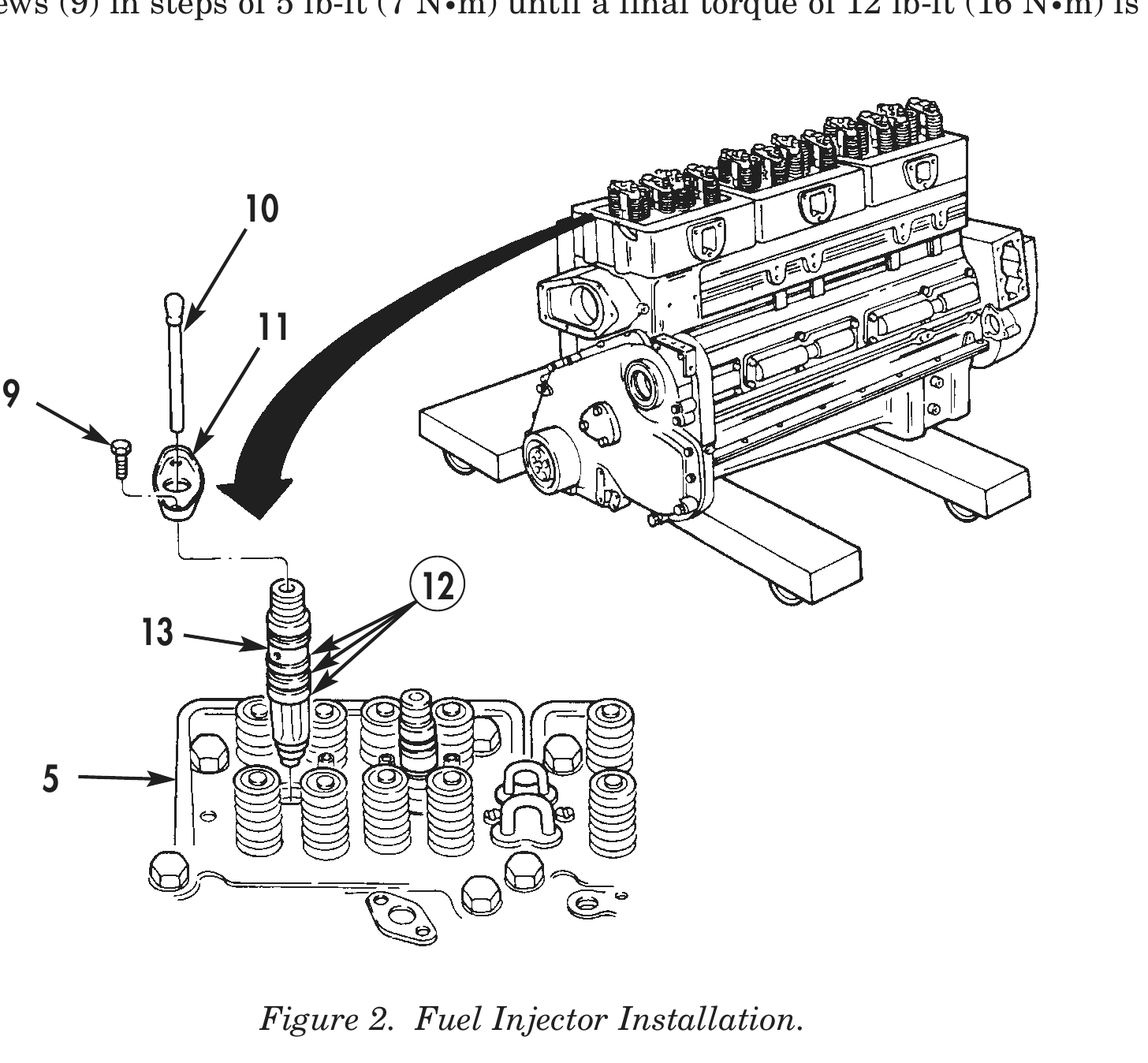
FUEL INJECTOR
1. Apply OE/HDO 10 lubricating oil to three new O-rings (12) and fuel injector (13).
2. Using injector puller, install fuel injector (13) in cylinder head (5).
3. Install retaining plate (11) on fuel injector (13) with two screws (9). Do not tighten screws.
4. Install detent plunger (10) on fuel injector (13).
5. Tighten screws (9) in steps of 5 lb-ft (7 N•m) until a final torque of 12 lb-ft (16 N•m) is obtained.
ROCKER ARM HOUSING
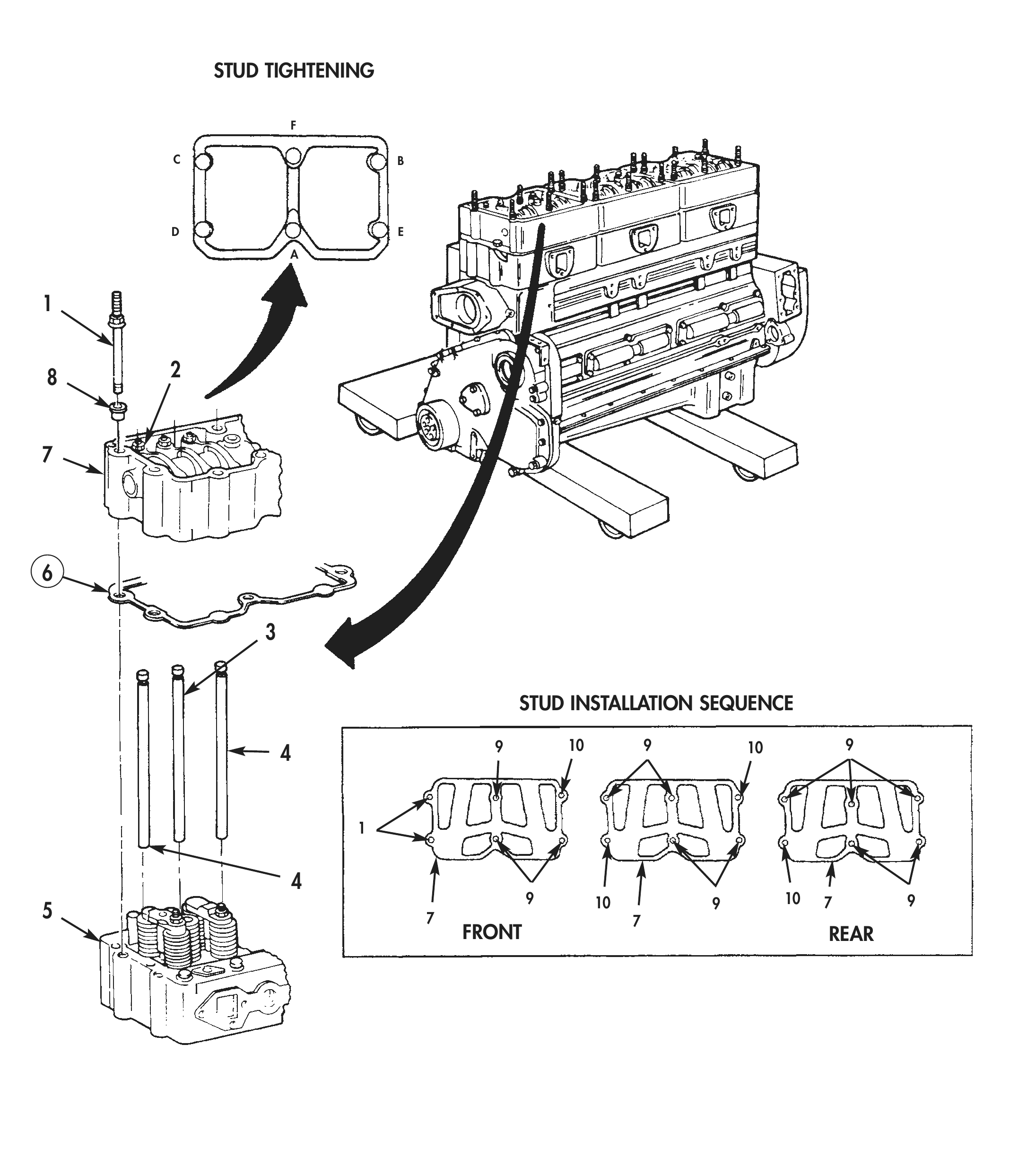
1. Install new gasket (6) on cylinder head (5).
2. Loosen six adjusting screws (2) three complete turns.
3. Apply GO-80/140 lubricating oil to ball ends of four intake and exhaust pushrods (4) and two injector pushrods (3).
4. Install four intake and exhaust pushrods (4) and two injector pushrods (3) on cam followers of cylinder head (5).
5. Install rocker arm housing (7) on cylinder head (5).
6. Install six new washer bearings (8) on rocker arm housing (7).
7. Install six rocker housing studs (1), (9), and (10) on rocker housings (7) as shown in figure 3. Tighten studs (1), (9), and (10) 65 lb-ft (68 N•m) in sequence shown in figure 3.
STUD TIGHTENING
F
C                            B
D                             E
A
8 2
STUD INSTALLATION SEQUENCE
9 10 9 10 9
                                                         9        10           9        10   7       9
5                                            7                         7
FRONT REAR
ROCKER ARM HOUSING (Contd)
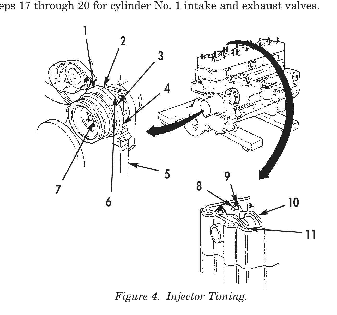
8. Using medium grit emery cloth, remove paint on timing marks (2), (3), and (4) on accessory drive pulley (1).
9. Rotate accessory drive pulley (1) clockwise until line in front of timing mark (2) aligns with pointer (6) on front gear cover (5).
10. Loosen adjusting screw nut (8) several turns.
11. Tighten adjusting screw (9) until all clearance is removed between rocker lever (10) and injector detent plunger.
12. Tighten adjusting screw (9) one additional turn.
13. Loosen adjusting screw (9) one complete turn until spring washer inside injector is against stop of injector.
14. Tighten adjusting screw (9) 5–6 lb-in (0.6–0.7 N•m).
15. Repeat step 14 several times to make certain adjusting screw (9) is correctly tightened.
16. Prevent adjusting screw (9) from turning and tighten adjusting screw nut (8) 45 lb-ft (61 N•m).
17. Loosen adjusting screw nut (8).
18. Place feeler gauge between rocker lever (10) and crosshead (11).
19. Slowly tighten screw (9) until rocker lever (10) touches feeler gauge.
ROCKER ARM HOUSING (Contd)
20. Hold adjusting screw (9) in place and tighten adjusting screw nut (8) 45 lb-ft (61 N•m).
21. Slowly rotate accessory drive pulley (1) clockwise until line in front of timing mark (3) aligns with pointer (6) on front gear cover (5).
22. Perform steps 10 through 16 for cylinder No. 6 injector.
23. Perform steps 17 through 20 for cylinder No. 3 intake and exhaust valves.
24. Slowly rotate accessory drive pulley (1) clockwise until line in front of timing mark (4) aligns with pointer (6) on front gear cover (5).
25. Perform steps 10 through 16 for cylinder No. 2 injector.
26. Perform steps 17 through 20 for cylinder No. 6 intake and exhaust valves.
27. Slowly rotate accessory drive pulley (1) clockwise until line in front of timing mark (2) aligns with pointer (6) on front gear cover (5).
28. Perform steps 10 through 16 for cylinder No. 4 injector.
29. Perform steps 17 through 20 for cylinder No. 2 intake and exhaust valves.
30. Slowly rotate accessory drive pulley (1) clockwise until line in front of timing mark (3) aligns with pointer (6) on front gear cover (5).
31. Perform steps 10 through 16 for cylinder No. 1 injector.
32. Perform steps 17 through 20 for cylinder No. 4 intake and exhaust valves.
33. Slowly rotate accessory drive pulley (1) clockwise until line in front of timing mark (4) aligns with pointer (6) on front gear cover (5).
34. Perform steps 10 through 16 for cylinder No. 5 injector.
35. Perform steps 17 through 20 for cylinder No. 1 intake and exhaust valves.
5 9 7 8 6 10
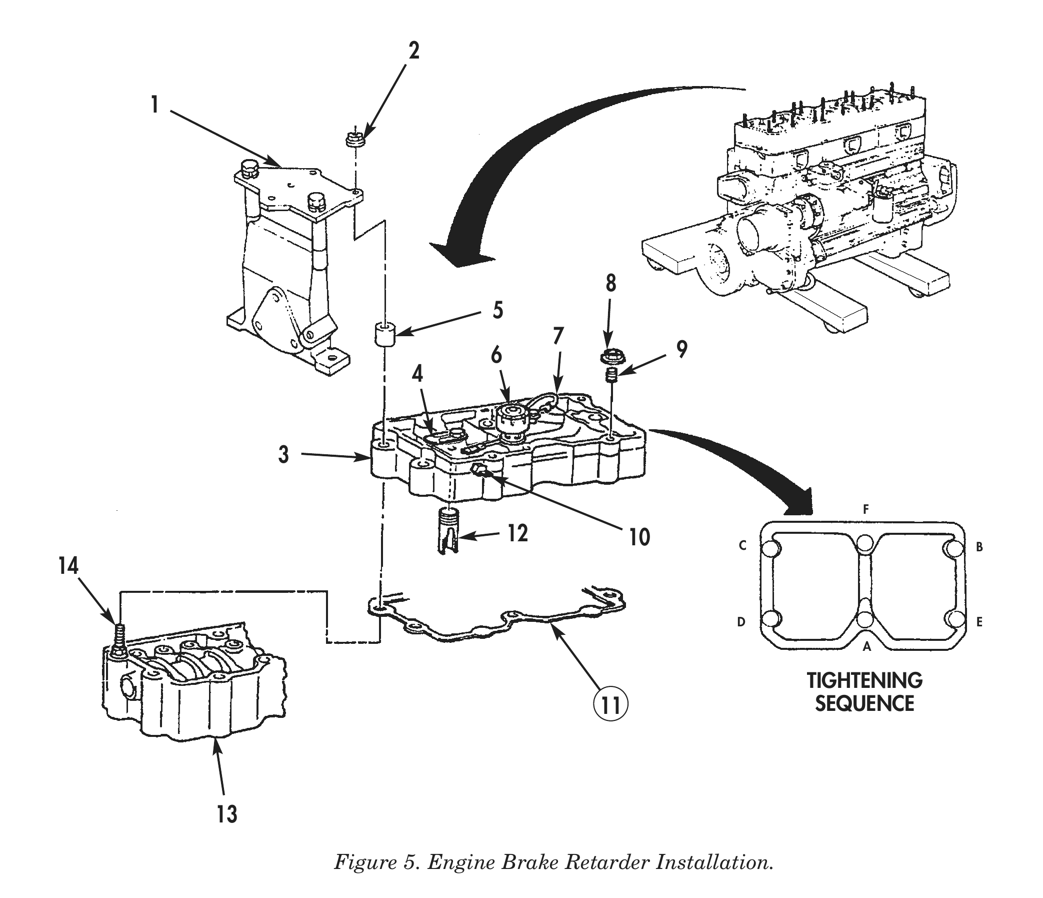
ENGINE BRAKE RETARDER
1. Install new gasket (11) on rocker arm housing (13).
2. Install engine brake retarder (3) on two rocker arm housing studs (14).
3. Install fan bracket (1) and two spacers (5) on two rocker housing studs (14).
4. Install six nuts (2) on rocker housing studs (14). Tighten nuts (2) 60 lb-ft (81 N•m) in sequence shown in figure 4.
5. Loosen locknut (8) and setscrew (9) until there is no pressure or tension.
6. Using feeler gauge, check slave piston (12) clearance between slave piston (12) and crosshead (4). Adjust clearance to 0.018 in. (0.457 mm).
7. Tighten locknut (8) 40 lb-ft (54 N•m).
8. Using feeler gauge, recheck slave piston (12) clearance.
9. Connect spade end of solenoid harness (7) to solenoid valve (6).
10. Connect receiver end of solenoid harness (7) to terminal (10) inside engine brake retarder (3).
ROCKER COVER
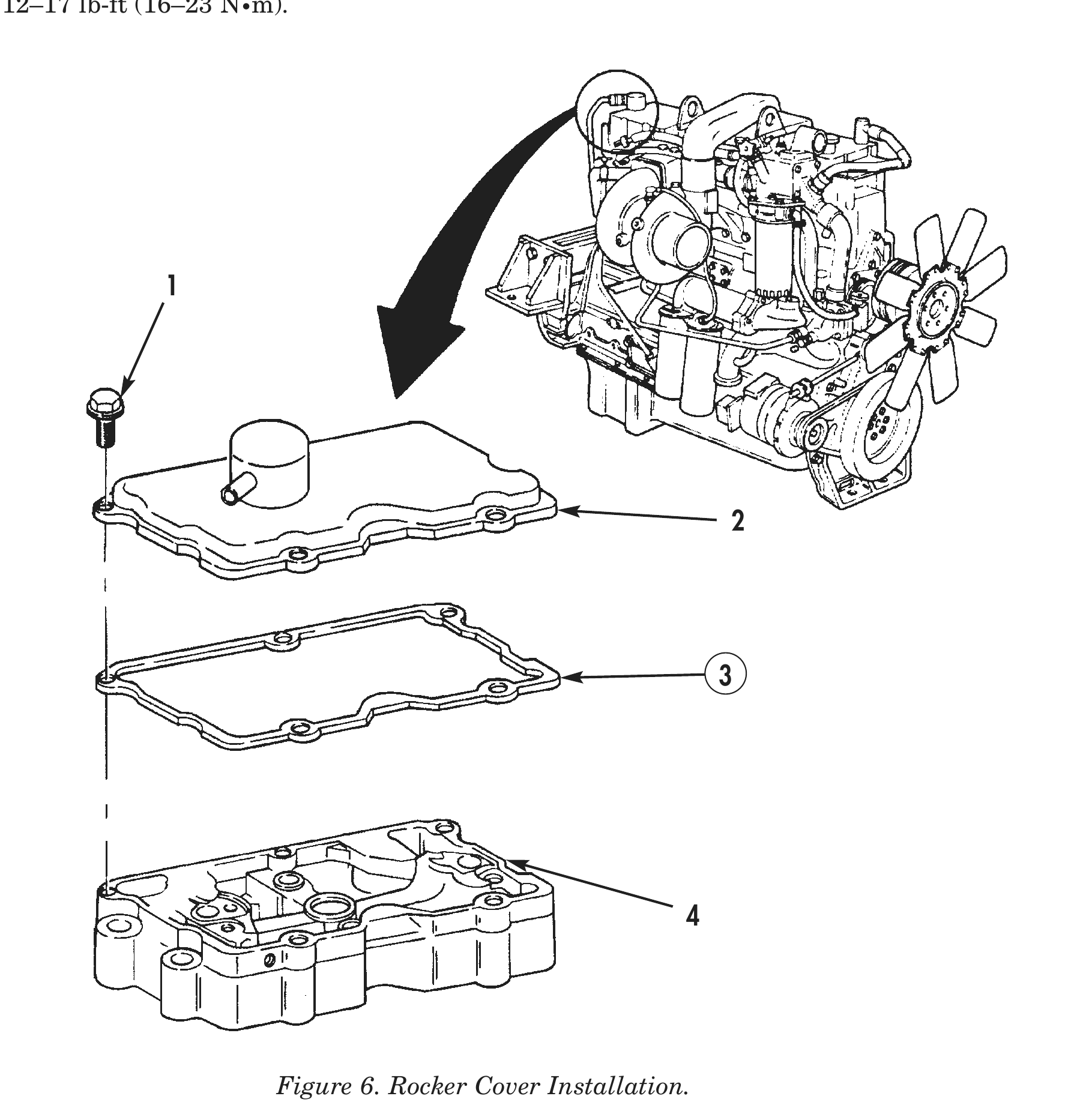
Install new gasket (3) and rocker cover (2) on engine brake retarder (4) with five screws (1). Tighten screws (1) 12–17 lb-ft (16–23 N•m).
END OF WORK PACKAGE