CYLINDER HEAD AND CYLINDER HEAD COMPONENTS REMOVAL
TM 9-2815-225-34&P · Work Package 0011 00
ROCKER COVER, ENGINE BRAKE RETARDER, ROCKER ARM HOUSING, FUEL INJECTOR, CYLINDER HEAD
INITIAL SETUP
Tools and Special Tools                              Equipment Condition
 General mechanic’s tool kit: automotive              Engine mounted on maintenance stand
    (Item 1, WP 0061 00)                                (WP 0009 00).
 Maintenance and repair shop equipment:               Engine accessories removed (WP 0010 00).
    automotive (Item 2, WP 0061 00)
 Automotive maintenance and repair
    supplemental set no. 2 (Item 3, WP 0061 00)
 Fuel injector puller (Item 8, WP 0061 00)

Material/Parts
 Lint-free cloth (Item 6, WP 0060 00)
ROCKER COVER
1. Remove five screws (1), rocker cover (2), and gasket (3) from engine brake retarder (4). Discard gasket (3).
2. Repeat step 1 to remove remaining two rocker covers (2).
ENGINE BRAKE RETARDER
1. Scribe a locating mark (7) on engine brake retarder (4) and rocker arm housing (10) before removal.
2. Bend tabs on locking plates (5) down and remove six nuts (6) and locking plates (5) securing engine brake retarder (4) on studs (11) in rocker arm housing (10). Discard locking plates (5).
3. Remove engine brake retarder (4), gasket (8), and O-ring (9) from rocker arm housing (10). Discard gasket (8) and O-ring (9).
4. Repeat steps 1 through 3 to remove remaining two engine brake retarders (4).
5. For engine brake retarder (4) repair, refer to WP 0030 00.
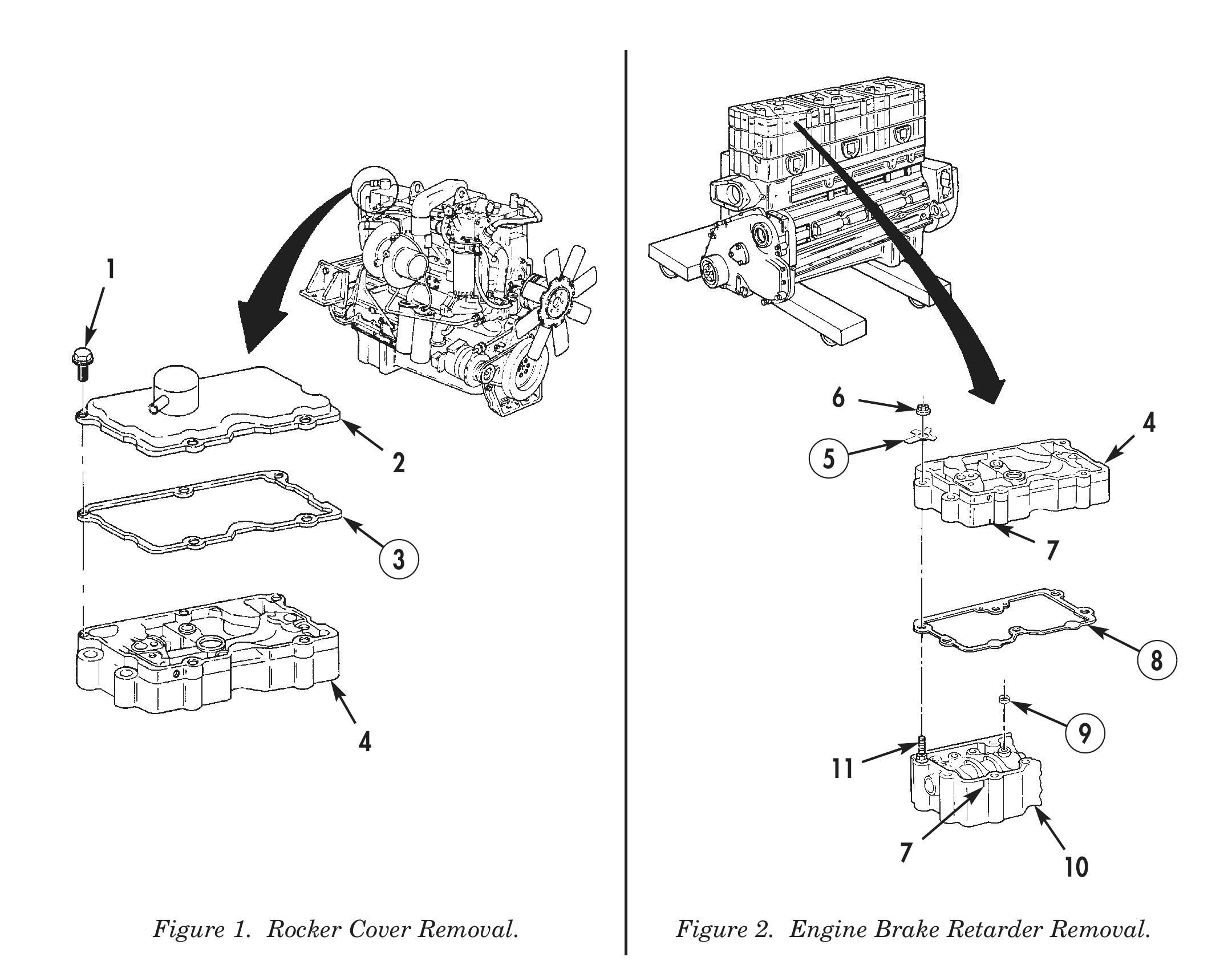
Figure 1. Rocker Cover Removal. Figure 2. Engine Brake Retarder Removal.
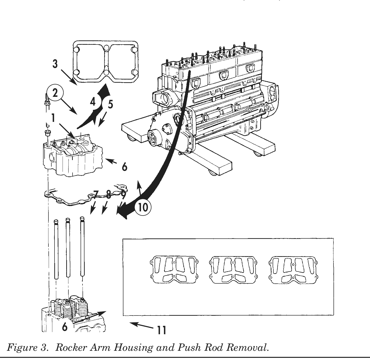
ROCKER ARM HOUSING
1. Scribe a locating mark (6) on rocker arm housing (1) and cylinder head (11) before removal.
2. Loosen six adjusting nuts (5) and screws (4) by turning counter-clockwise to until tension is relieved.
3. Remove six rocker arm housing studs (3) and washer bearings (2) securing rocker arm housing (1) to cylinder head (11). Discard washer bearings (2).
4. Remove rocker arm housing (1) and gasket (10) from cylinder head (11). Discard gasket (10).
5. Remove two intake pushrods (7), injector pushrods (8), and exhaust pushrods (9) from cylinder head (11).
6. Repeat steps 1 through 5 to remove remaining two rocker arm housings (1).
7. For rocker arm housing and shaft repair, refer to WP 0020 00.
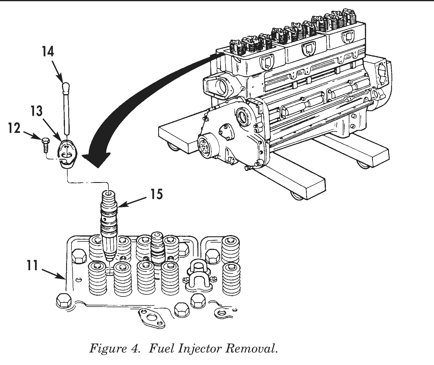
FUEL INJECTOR
1. Remove two screws (12) and retaining plate (13) securing fuel injector (15) in cylinder head (11).
2. Remove detent plunger (14) from fuel injector (15).
3. Using fuel injector puller, remove fuel injector (15) from cylinder head (11).
4. Wrap each fuel injector (15) in clean lint free cloth after removal to prevent dirt from entering fuel injector (15) openings.
5. Repeat steps 1 through 4 for remaining fuel injectors (15).
6. For fuel injector (15) repair, refer to WP 0032 00.
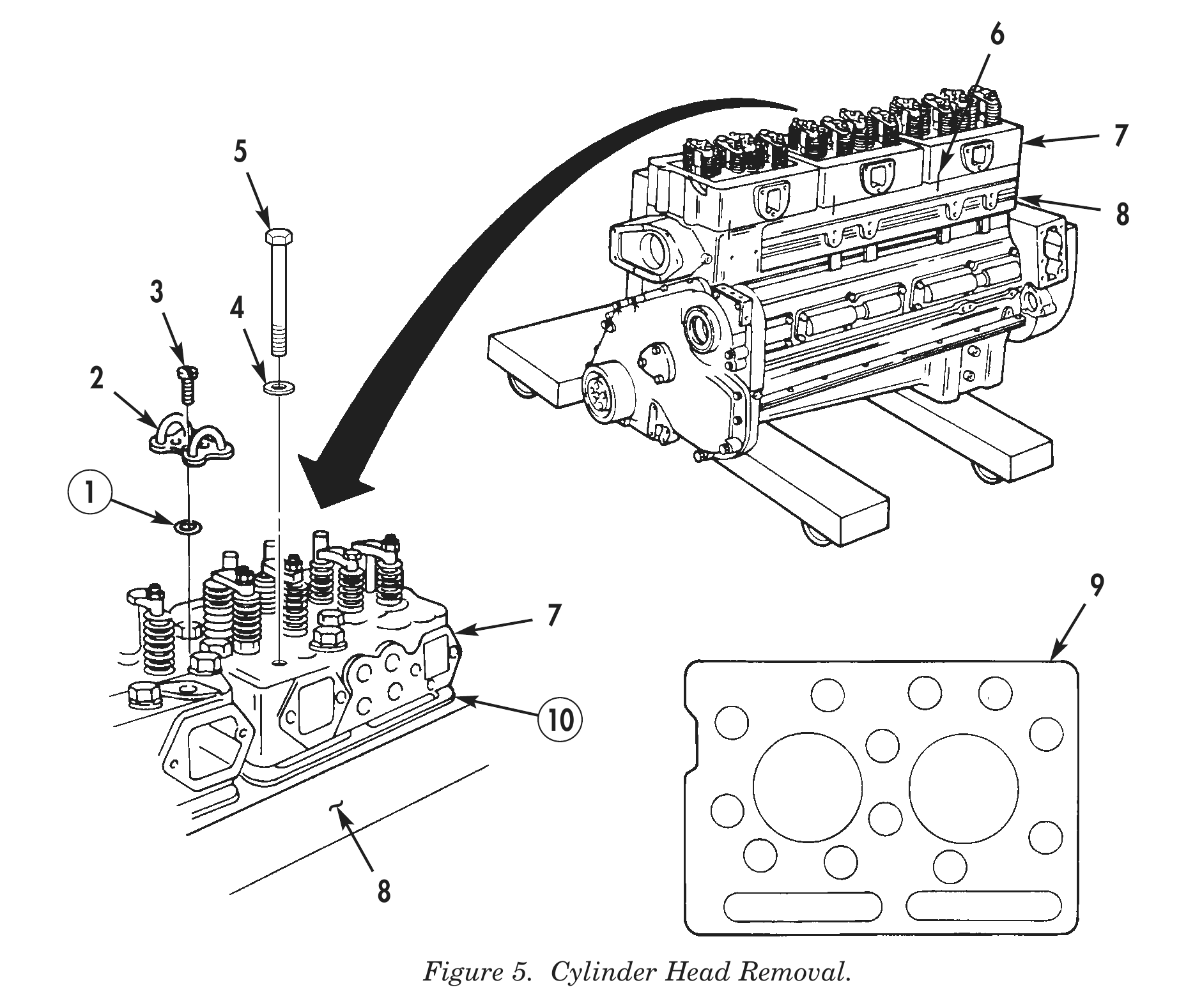
CYLINDER HEAD
1. Scribe a locating mark (6) on cylinder head (7) and cylinder block (8) before removal.
2. Remove four screws (3), fuel crossover connection (2), and four O-rings (1) from cylinder head (7). Discard O-rings (1).
3. Remove eight screws (3), two fuel crossover connections (2), and eight O-rings (1) from center cylinder head (7). Discard O-rings (1).
4. Remove twelve bolts (5) and washers (4) in sequence (9) securing cylinder head (7) to cylinder block (8).
5. Remove cylinder head (7) and gasket (10) from cylinder block (8). Discard gasket (10).
6. Repeat steps 1 through 5 for remaining cylinder heads (7).
7. For cylinder head repair (7), refer to WP 0014 00.
END OF WORK PACKAGE