FUEL INJECTOR
TM 9-2815-225-34&P · Work Package 0032 00
DISASSEMBLY, CLEANING AND INSPECTION, ASSEMBLY
INITIAL SETUP
Tools and Special Tools                               Equipment Condition
 General mechanic’s tool kit:                          Fuel injector removed from engine
    automotive (Item 1, WP 0061 00)                      (WP 0011 00).
 Maintenance and repair shop equipment:
    automotive (Item 2, WP 0061 00)
 Automotive maintenance and repair
    supplemental set no. 2 (Item 3, WP 0061 00)
 Injector stand (Item 11, WP 0061 00)
 Body and injector cup wrench
    (Item 12, WP 0061 00)

Materials/Parts
 Lubricating oil (Item 19, WP 0060 00)
 Prussian blue (Item 9, WP 0060 00)
 Diesel fuel (Item 18, WP 0060 00)
 Spring (Item 1, Table 16, WP 0062 00)
 Three gaskets (Item 2, Table 16, WP 0062 00)
 Filter screen (Item 3, Table 16, WP 0062 00)
 Gasket (Item 4, Table 16, WP 0062 00)
DISASSEMBLY
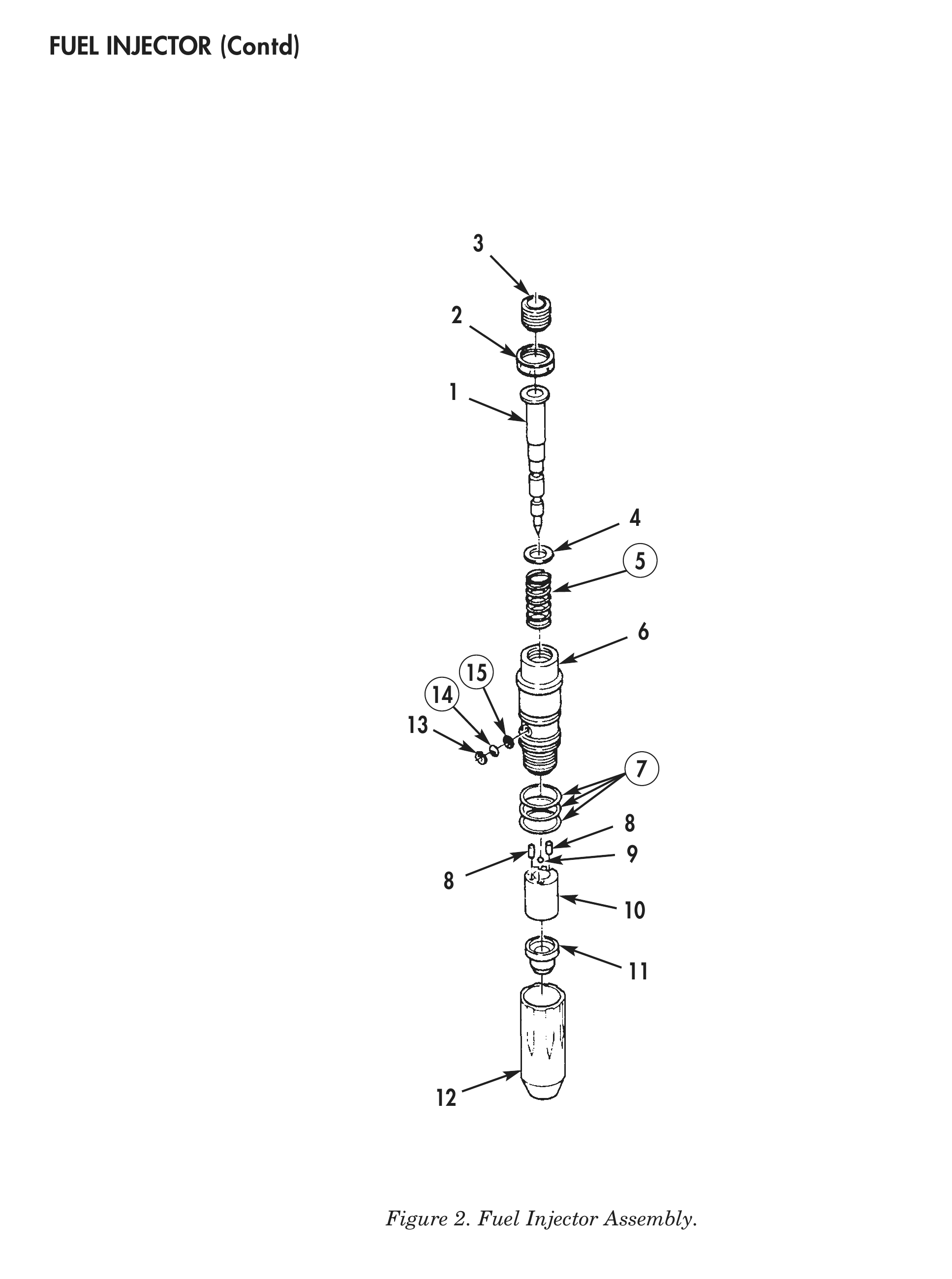
1. Remove top-stop locknut (2) and top-stop screw (3) from top-stop adapter (6).
2. Remove plunger (1), washer (4), and injector spring (5) from top-stop adapter (6). Discard spring (5).
3. Remove three gaskets (7) from top-stop adapter (6). Discard gaskets (7).
4. Remove filter screen clip (13), filter screen (14), and gasket (15) from top-stop adapter (6). Discard filter screen (14) and gasket (15).
5. Install injector in injector stand. Using body and injector cup wrench, loosen cup retainer (12) on top-stop adapter (6). Remove injector from injector stand.
6. Remove cup retainer (12) from top-stop adapter (6).
7. Remove barrel (10) and injector cup (11) from cup retainer (12).
8. Remove two roll pins (8) and check ball (9) from barrel (10).
CLEANING AND INSPECTION
1. For general parts cleaning information, refer to CLEANING, WP 0051 00.
2. For general parts inspection information, refer to INSPECTION, WP 0051 00.
3. Inspect cup retainer (12) for stripped threads, nicks and burrs.
4. Inspect top-stop adapter (6) for stripped threads.
5. Inspect top-stop adapter (6) for nicks and burrs around gasket sealing area and mating surfaces.
6. Inspect top-stop adapter (6) for obstructions around orifice and fuel passage openings.
7. Inspect check ball (9) for nicks and burrs.
8. Using a depth micrometer, measure barrel (10) ball seat depth. Maximum barrel (10) ball seat depth allowed is 0.050 in. (1.27 mm).
9. Inspect barrel (10) for scoring, nicks and burrs.
10. Inspect barrel (10) for carbon, burrs, distorted radius, and blockage.
11. Inspect barrel (10) for loose or cracked fuel passages.
CLEANING AND INSPECTION (Contd)
12. Inspect plunger (1) for scuffing or scoring.
13. Inspect injector cup (11) for enlarged or distorted spray holes.
14. Apply prussian blue to plunger (1) and install in cup (11) and rotate 90° to check plunger seat pattern. If less than 40% of seat area is covered, replace cup (11).
ASSEMBLY
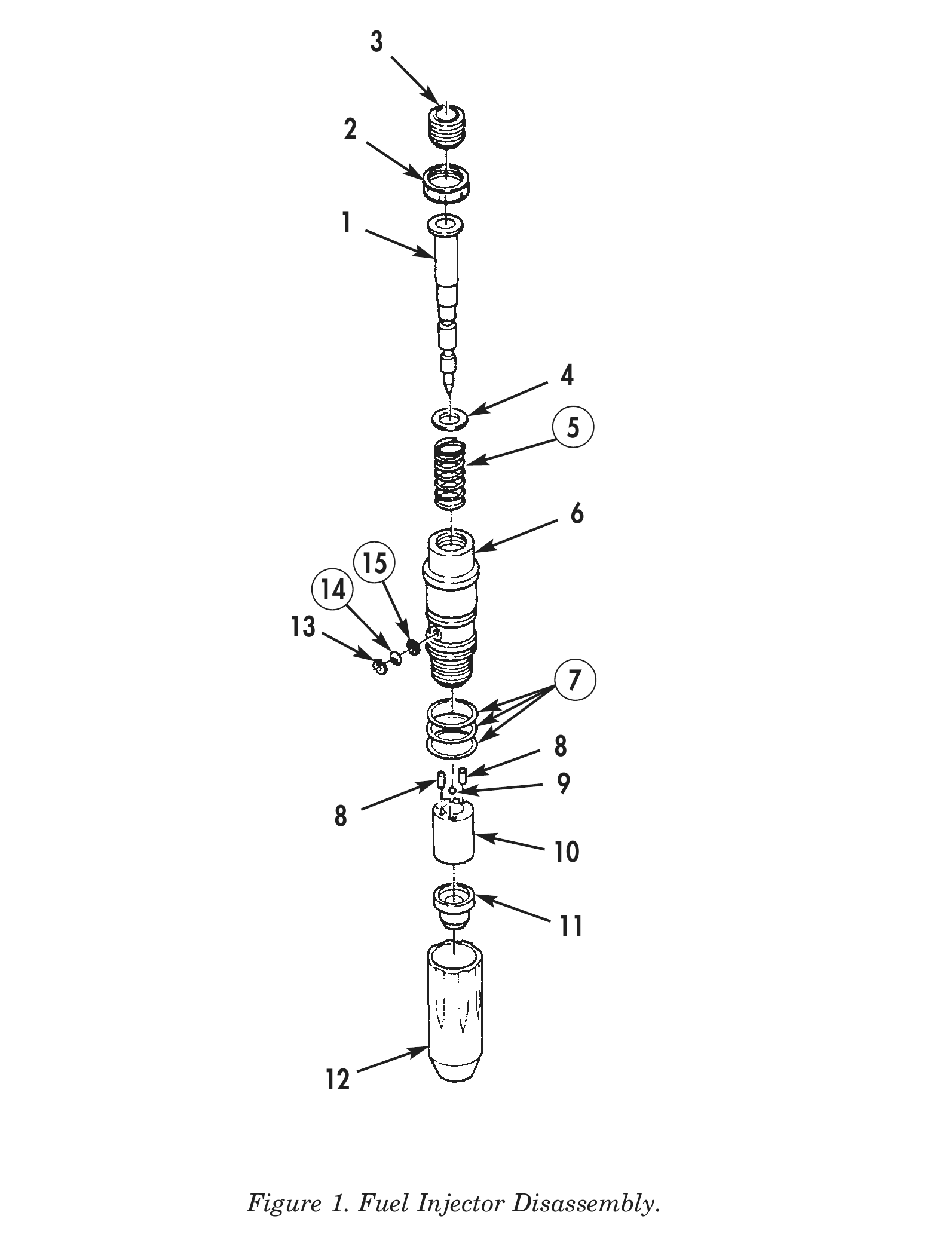
1. Install check ball (9) on barrel (10).
2. Install two roll pins (8) in barrel (10).
3. Install barrel (10) and injector cup (11) in top-stop adapter (6). Ensure check ball (9) stays positioned on barrel (10).
4. Install cup retainer (12) on top-stop adapter (6) finger tight.
5. Install plunger (1) in top-stop adapter (6).
6. Install injector in injector stand. Tighten stud on injector stand 75 lb-in. (8.5 N•m) to align injector cup (11) with plunger (1). Using body and injector cup wrench, tighten cup retainer (12) 53–57 lb-ft (72–77 N•m). Remove injector from injector stand.
7. Remove plunger (1) from top-stop adapter (6) and coat plunger (1) with diesel fuel.
8. Allow diesel fuel to run off plunger (1) into top-stop adapter (6) and barrel (10).
9. Install plunger (1) in barrel (10) leaving a 0.050 in. (1.27 mm) gap between top of plunger (1) and top-stop adapter (6).
10. Seat plunger (1) in injector cup (11) by pushing down.
11. Hold plunger (1) firmly in injector cup (11) and rotate 90°.
12. Turn injector over and release plunger (1). Plunger (1) should slide out immediately. If plunger (1) does not slide out. Plunger (1) and injector cup (11) are not aligned. Disassemble injector and realign.
13. Repeat steps 7 through 12 until correct plunger (1) to injector cup (11) alignment is obtained.
14. Install three new gaskets (7) on top-stop adapter (6).
15. Install new gasket (15), new filter screen (14), and filter screen clip (13) in top-stop adapter (6).
16. Install new injector spring (5), washer (4), and plunger (1) in top-stop adapter (6).
17. Install top-stop locknut (2) and top-stop screw (3) in top-stop adapter (6).
18. For installation of fuel injector, refer to WP 0043 00.