OIL COOLER
TM 9-2815-225-34&P · Work Package 0021 00
DISASSEMBLY, CLEANING AND INSPECTION, ASSEMBLY
INITIAL SETUP
Tools and Special Tools                                Materials/Parts (Contd)
 General mechanic’s tool kit: automotive                Two O-rings (Item 16, Table 6, WP 0062 00)
    (Item 1, WP 0061 00)                                Element (Item 17, Table 6, WP 0062 00)
 Maintenance and repair shop equipment:                 Spring (Item 18, Table 6, WP 0062 00)
    automotive (Item 2, WP 0061 00)                     Lockwasher (Item 19, Table 6, WP 0062 00)
 Automotive maintenance and repair                      Gasket (Item 20, Table 6, WP 0062 00)
    supplemental set no. 2 (Item 3, WP 0061 00)         O-ring (Item 21, Table 6, WP 0062 00)

Materials/Parts                                        Equipment Condition
 Pipe sealant (Item 25, WP 0060 00)                     Oil cooler removed from engine (WP 0009 00).
 Lubricating oil, OE/HDO 30
   (Item 20, WP 0060 00)
 Twelve lockwashers
   (Item 1, Table 6, WP 0062 00)
 O-ring (Item 2, Table 6, WP 0062 00)
 Gasket (Item 3, Table 6, WP 0062 00)
 Gasket (Item 4, Table 6, WP 0062 00)
 Spring (Item 5, Table 6, WP 0062 00)
 Spring (Item 6, Table 6, WP 0062 00)
 Gasket (Item 7, Table 6, WP 0062 00)
 O-ring (Item 8, Table 6, WP 0062 00)
 Oil cooler core (Item 9, Table 6, WP 0062 00)
 Vent valve (Item 10, Table 6, WP 0062 00)
 Lockwasher (Item 11, Table 6, WP 0062 00)
 Gasket (Item 12, Table 6, WP 0062 00)
 Spring (Item 13, Table 6, WP 0062 00)
 Gasket (Item 14, Table 6, WP 0062 00)
 Two retaining rings
   (Item 15, Table 6, WP 0062 00)
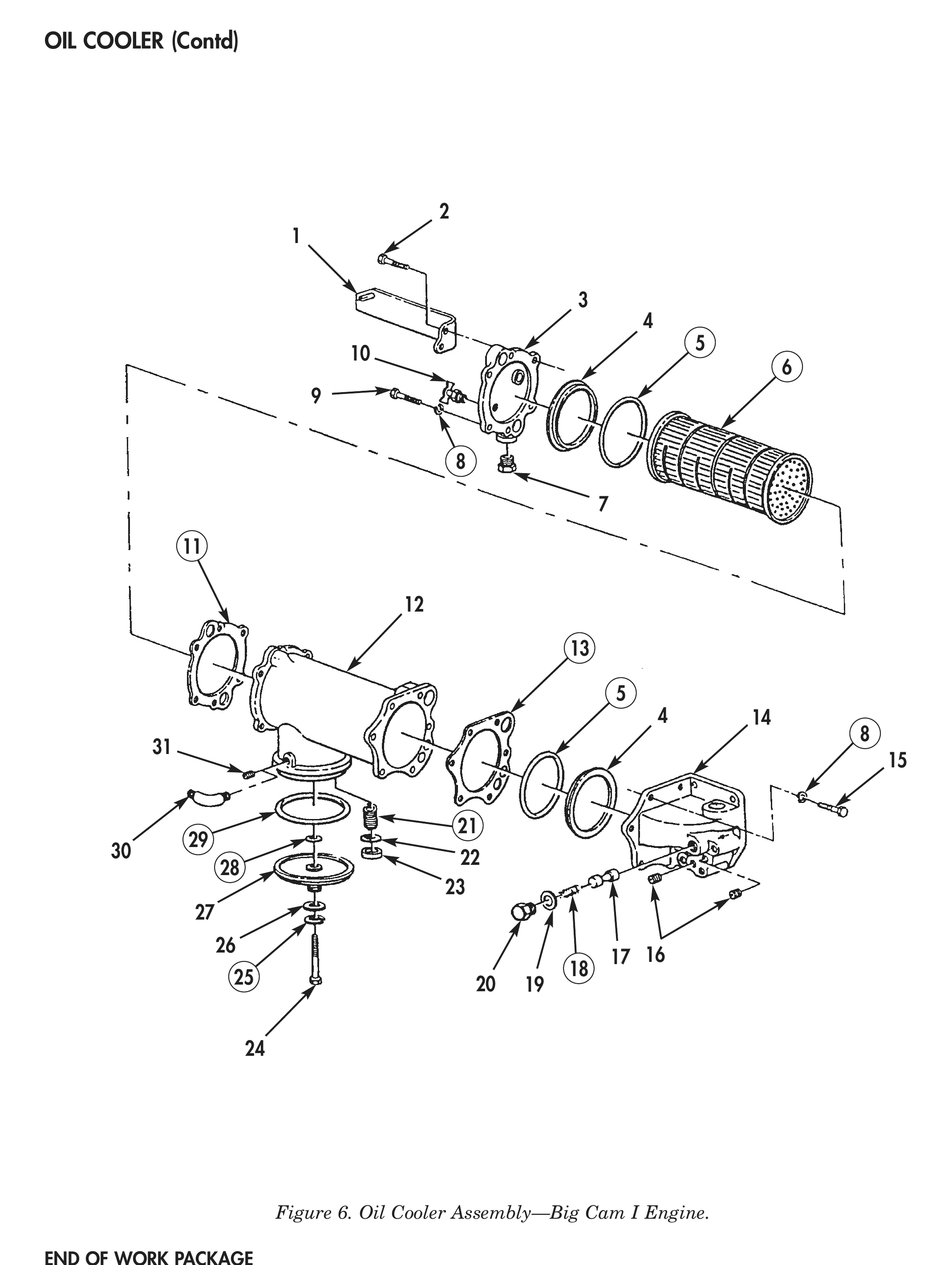
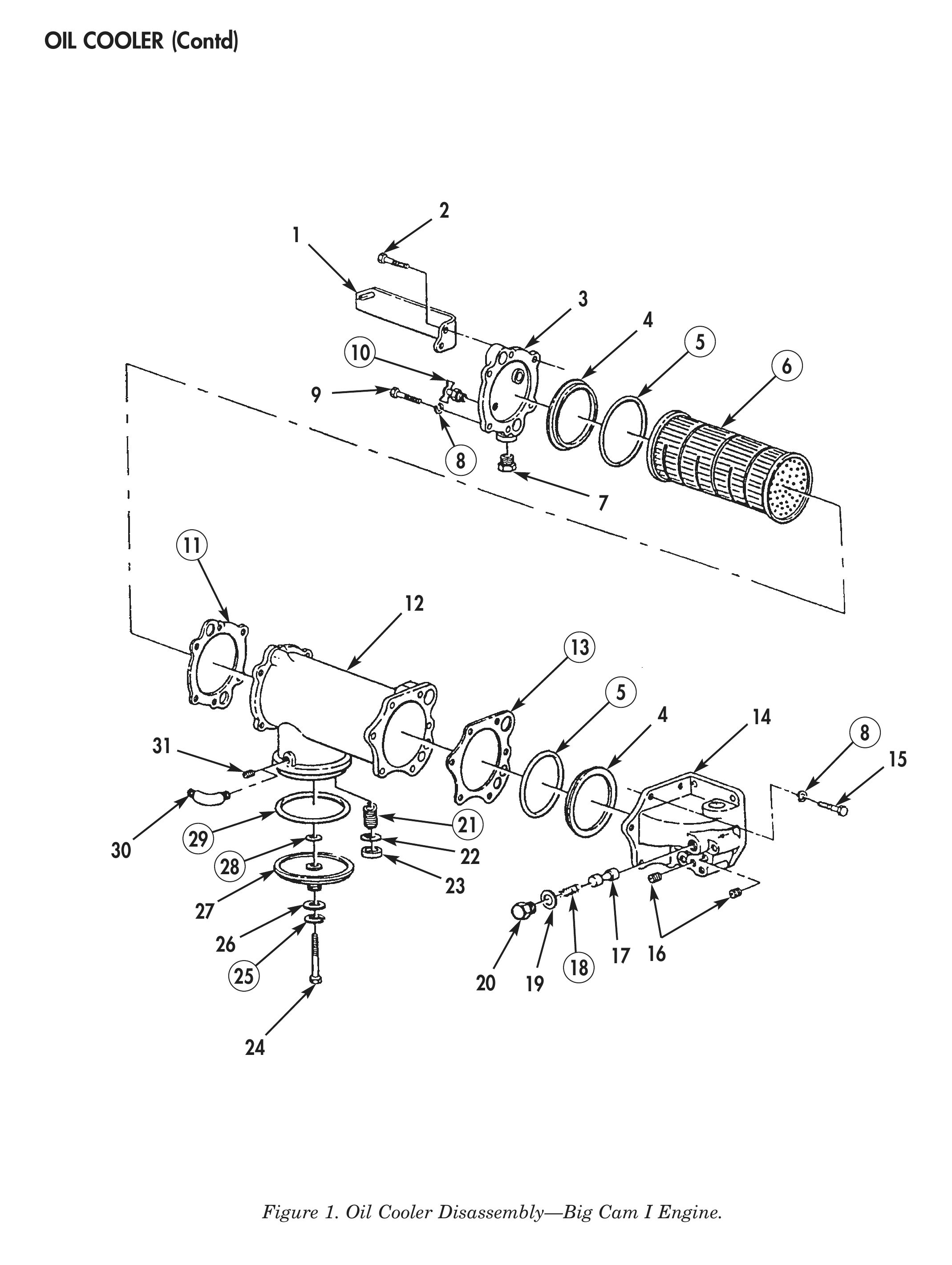
BIG CAM I DISASSEMBLY
1. For removal of oil cooler, refer to WP 0009 00.
2. Remove pipe plug (7) and vent valve (10) from oil cooler rear cover (3). Discard vent valve.
3. Remove two pipe plugs (16) from oil cooler front cover (14).
4. Remove expansion plug (31) or elbow (30) from oil cooler housing (12).
5. Remove screw (24), lockwasher (25), washer (26), head (27), gasket (28), and O-ring (29) from oil cooler housing (12). Discard lockwasher (25), gasket (28), and O-ring (29).
6. Remove seat (23), disc (22), and spring (21) from oil cooler housing (12). Discard spring (21).
7. Remove plug (21), spacer (22), spring (21), and plunger (18) from oil cooler front cover (14). Discard spring (19).
8. Remove six screws (15), lockwashers (8), oil cooler front cover (14), and gasket (13) from oil cooler housing (12). Discard lockwashers (8) and gasket (13).
9. Remove six screws (2) and (9), four lockwashers (8), bracket (1), oil cooler rear cover (3), and gasket (11) from oil cooler housing (12). Discard lockwashers (8) and gasket (11).
10. Remove two retaining rings (4), O-rings (5), and element (6) from oil cooler housing (12). Discard O-rings (5) retaining rings and, element (6).
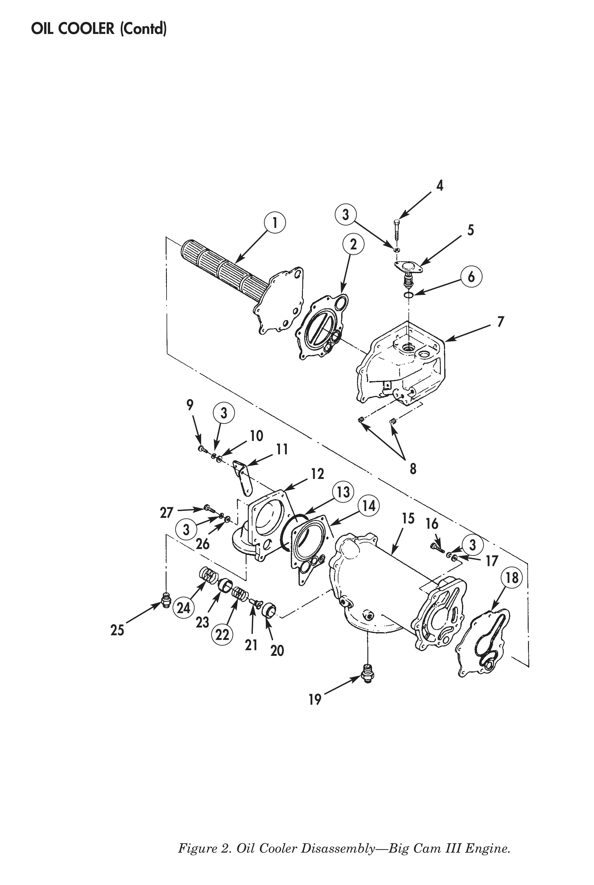
BIG CAM III DISASSEMBLY
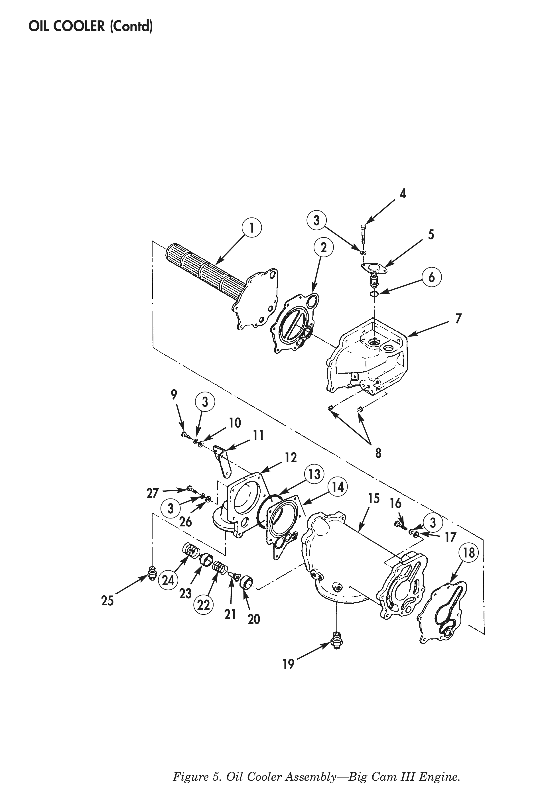
1. For removal of oil cooler, refer to WP 0009 00.
2. Remove adapter (25) from head (12).
3. Remove three screws (9), lockwashers (3), washers (10), and bracket (11) from head (12). Discard lockwashers (3).
4. Remove three screws (27), lockwashers (3), washers (26), head (12), O-ring (13), and gasket (14) from oil cooler housing (15). Discard lockwashers (3), O-ring (13), and gasket (14).
5. Remove spring (24), bypass valve piston (23), spring (22), bypass valve plunger (21), and pressure sensing piston (20) from oil cooler housing (15). Discard spring (22) and (24).
6. Remove six screws (16), lockwashers (3), washers (17), support (7), and gasket (2) from oil cooler housing (15). Discard lockwashers (3) and gasket (2).
7. Remove oil cooler core (1) and gasket (18) from oil cooler housing (15). Discard gasket (18) and oil cooler core (1).
8. Remove two screws (4), lockwashers (3), valve (5), and O-ring (6) from support (7). Discard lockwashers (3) and O-ring (6).
9. Remove two pipe plugs (8) from support (7).
10. Remove adapter (19) from oil cooler housing (15).
CLEANING AND INSPECTION
1. For general parts cleaning information, refer to CLEANING, WP 0051 00.
2. For general parts inspection information, refer to INSPECTION, WP 0051 00.
3. Inspect oil cooler rear cover (1), oil cooler housing (2), and oil cooler front cover (3) for cracks, plugged oil passages, and stripped threads or damaged holes. Repair all stripped threads.
4. Inspect head (4), oil cooler housing (5), and support (6) for cracks, plugged oil passages, and stripped threads or damaged holes. Repair all stripped threads.
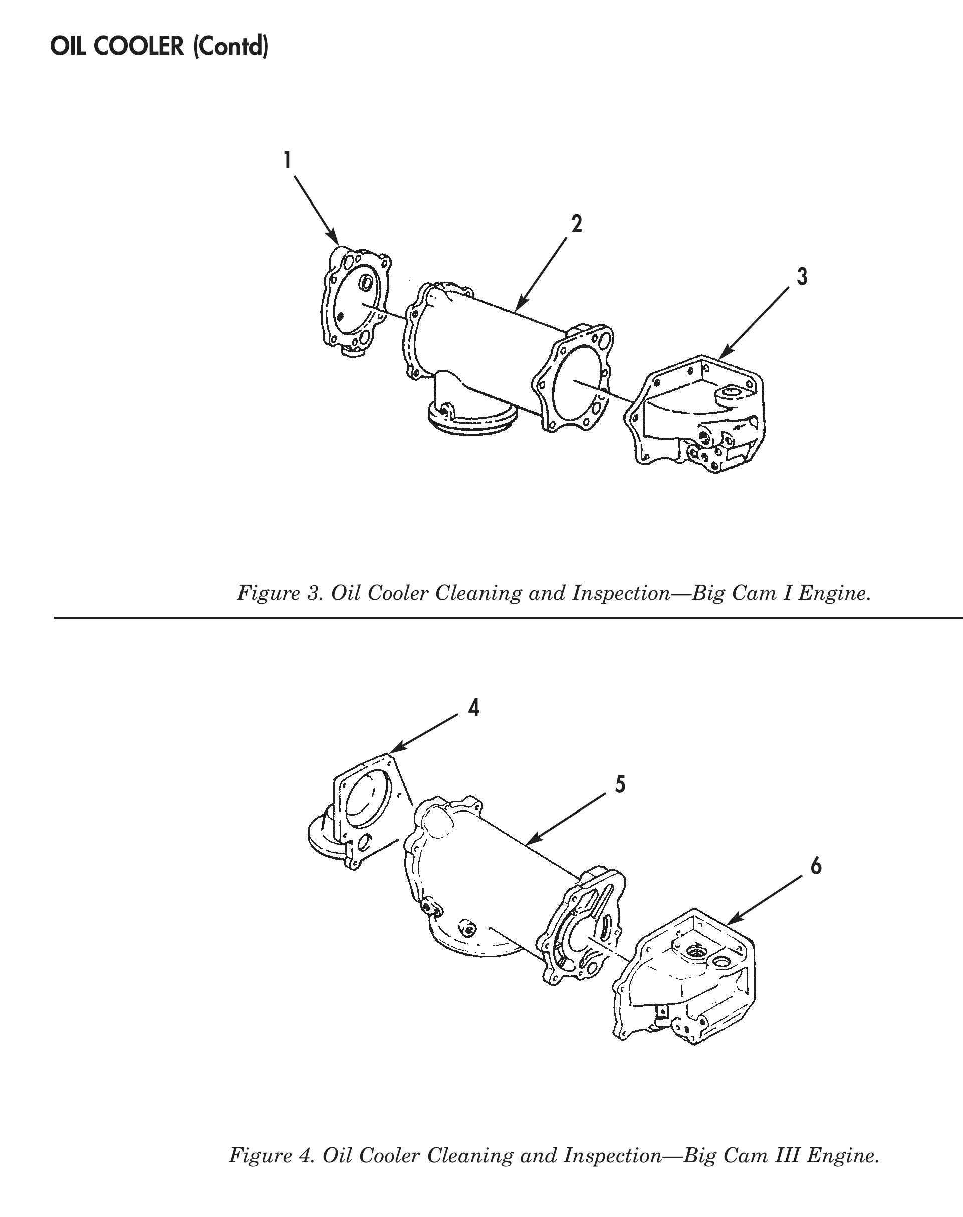
Figure 3. Oil Cooler Cleaning and Inspection—Big Cam I Engine.
Figure 4. Oil Cooler Cleaning and Inspection—Big Cam III Engine.
BIG CAM III ASSEMBLY
1. Install adapter (19) in oil cooler housing (15).
2. Apply pipe sealant on two pipe plugs (8) and install in support (7). Tighten pipe plugs (8) 60–84 lb-in. (7–10 N•m).
3. Apply OE/HDO 30 lubricating oil to new O-ring (6). Install O-ring (6) and valve (5) in support (7) with two new lockwashers (3) and screws (4). Tighten screws (4) 30–35 lb-ft (41–48 N•m).
4. Install new gasket (18), new oil cooler core (1), new gasket (2), and support (7) on oil cooler housing (15) with six washers (17), new lockwashers (13), and screws (16). Tighten screws (16) 30–35 lb-ft (41–48 N•m).
5. Install pressure sensing piston (20), bypass valve plunger (21), new spring (22), bypass valve piston (23), and new spring (24) in oil cooler housing (15).
6. Apply OE/HDO 30 lubricating oil to new O-ring (13) and install new gasket (14), O-ring (13), and head (12) on oil cooler housing (15) with three washers (26), new lockwashers (3), and screws (27). Do not tighten screws (27).
7. Install bracket (11) on head (12) with three washers (10), new lockwashers (3), and screws (9). Tighten screws (9) and (30) 30–35 lb-ft (41–48 N•m).
8. Install adapter (25) in head (12).
9. For installation of oil cooler, refer to WP 0046 00.
BIG CAM I ASSEMBLY
1. Apply OE/HDO 30 lubricating oil to two new O-rings (5) and install on new element (6).
2. Align element (6) to oil cooler housing (12) and install in oil cooler housing (12). Ensure O-rings (5) are not pinched or twisted.
3. Install two new retaining rings (4) in oil cooler housing (12).
4. Install new gasket (11), oil cooler rear cover (3), and bracket (1) on oil cooler housing (12) with four new lockwashers (8) and six screws (2) and (9). Tighten screws (2) and (9) 30–35 lb-ft (41–48 N•m).
5. Install new gasket (13) and oil cooler front cover (14) on oil cooler housing (12) with six new lockwashers (8) and screws (15). Tighten screws (15) 30–35 lb-ft (41–48 N•m).
6. Install plunger (17), new spring (18), spacer (19), and plug (20) in oil cooler front cover (14).
7. Install new spring (21), disc (22), and seat (23) in oil cooler housing (12).
8. Apply OE/HDO 30 lubricating oil on new O-ring (29) and install in oil cooler housing (12).
9. Install new gasket (28) and head (27) on oil cooler housing (12) with washer (26), new lockwasher (25), and screw (24).
10. Install expansion plug (32) or elbow (31) on oil cooler housing (12).
11. Apply pipe sealant on two pipe plugs (17) and install in oil cooler front cover (14).
12. Apply pipe sealant on pipe plug (7) and new vent valve (10) and install in oil cooler rear cover (3).
13. For installation of oil cooler, refer to WP 0046 00.