BIG CAM I ENGINE INSTALLATION
TM 9-2815-225-34&P · Work Package 0049 00
INITIAL SETUP
Tools and Special Tools                                Equipment Condition
 General mechanic’s tool kit: automotive                Horn wire removed (TM 9-2320-283-20)
    (Item 1, WP 0061 00)                                Grille shell removed (TM 9-2320-283-20)
 Maintenance and repair shop equipment:                 Fenders removed (TM 9-2320-283-20)
    automotive (Item 2, WP 0061 00)                     Upper radiator fan shroud removed
 Lifting sling (Item 42, WP 0061 00)                      (TM 9-2320-283-20)
 Lifting brackets (Item 43, WP 0061 00)                 Steering system to proper level removed
                                                          (TM 9-2320-283-20)
Materials/Parts                                         Transmission oil cooler lines removed
 Ground strap starwasher                                  (TM 9-2320-283-20)
   (Item 1, Table 30, WP 0062 00)                       Air reservoir draincocks opened
 Alternator adjusting rod lockwasher                      (TM 9-2320-283-20)
   (Item 2, Table 30, WP 0062 00)                       Bumper and towing eyes removed
 Drive belts (Item 3, Table 30, WP 0062 00)               (TM 9-2320-283-20)
 Trunion retaining pin                                  Brush guard and spotter mirrors removed
   (Item 4, Table 30, WP 0062 00)                         (TM 9-2320-283-20)
 Two starter motor terminal lockwashers
   (Item 5, Table 30, WP 0062 00)                      Personnel Required
 Two transmission shift control cable                   Two assistants
   lockwashers (Item 6, Table 30, WP 0062 00)
 Two transmission shift control cable locknuts
   (Item 7, Table 30, WP 0062 00)
 Two transmission modulator control bracket
   lockwashers (Item 8, Table 30, WP 0062 00)
 Transmission modulator control link retaining
   pin (Item 9, Table 30, WP 0062 00)
 Plastic tie (Item 10, Table 30, WP 0062 00)
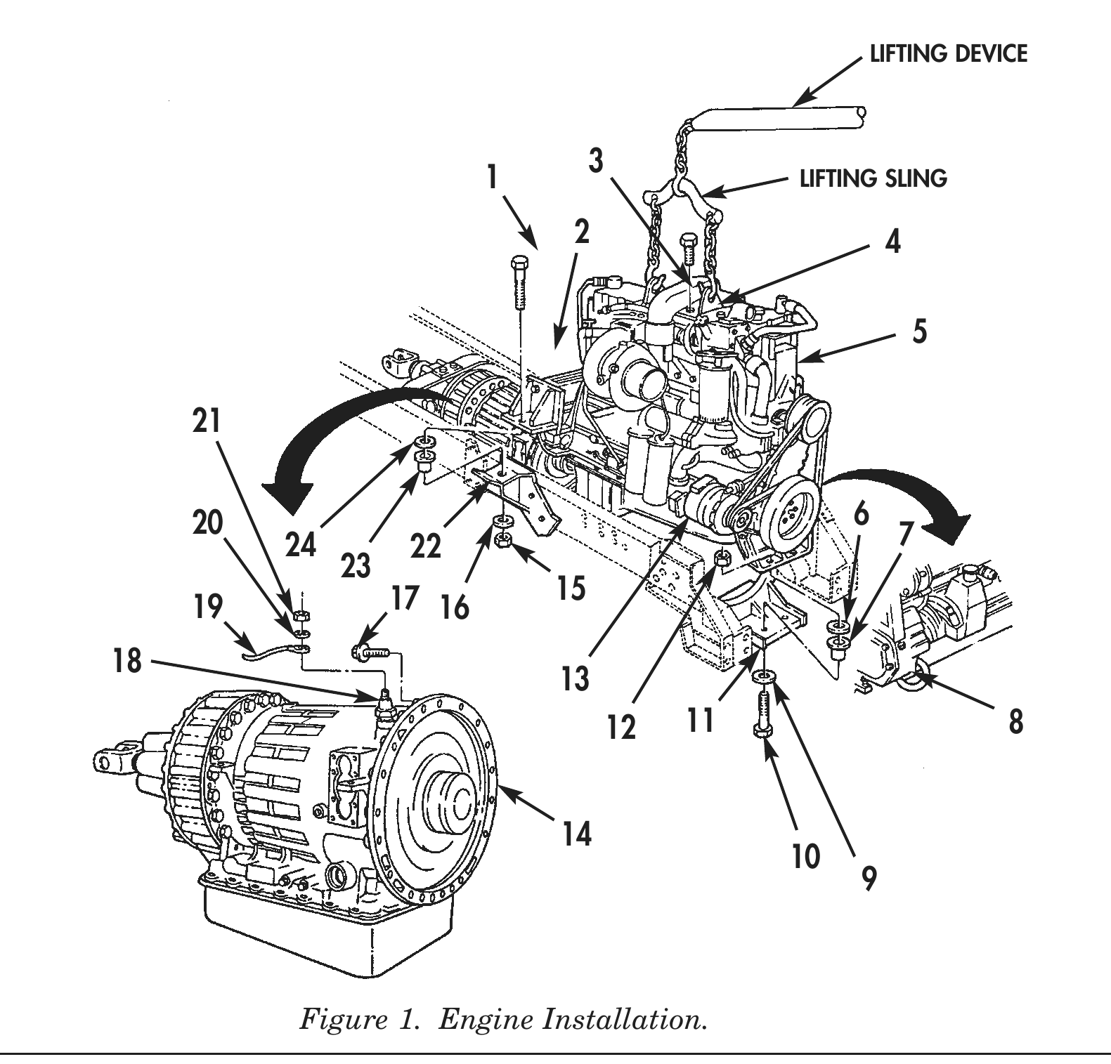
1. Attach two lifting brackets (4) with four bolts (3), lifting sling, and lifting device to engine (5).
2. Using lifting device, lifting sling, and assistant, position engine over vehicle frame (22).
3. Position two rear vibration insulators (23) and rear frame flat washers (24) on rear frame engine mounting brackets (2).
4. Position two front vibration insulators (7) and front frame flat washers (6) on front engine crossmember (11).
5. Using lifting device and lifting sling, lower engine (5) into vehicle frame (22). Ensure there is proper clearance between power steering pump (8) and alternator (13) during lowering of engine (5).
6. Secure engine (5) to two rear engine mounts (2) with two rear engine mount bolts (1), washers (16), and nuts (15). Tighten nuts (15) finger-tight.
7. Secure engine (5) to front engine crossmember (2) with two front engine mount washers (9), bolts (10), and nuts (12). Tighten nuts (12) finger-tight.
8. Remove lifting device, lifting sling, and lifting brackets (4) from engine (5).
9. Using suitable drift pin and transmission jack, align transmission mounting holes (14) to flywheel housing mounting holes and install twelve transmission bolts (17). Tighten bolts (17) 60 lb-ft (80 N•m).
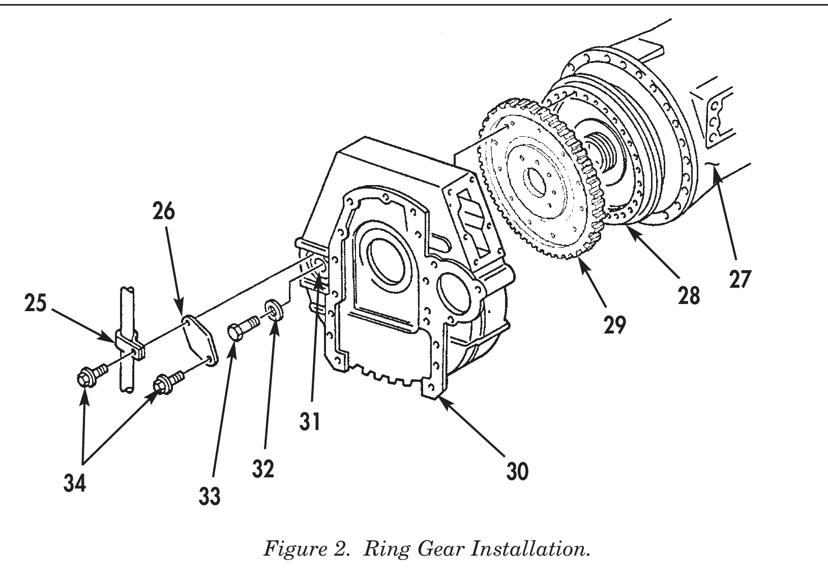
10. Attach ring gear (29) to flywheel (28) with twelve flywheel washers (32) and bolts (33) through flywheel bolt access hole (31). Alternately tighten bolts (33) 42–48 lb-ft (57–65 N•m).
11. Tighten two rear engine mount nuts (15) 270–295 lb-ft (366–400 N•m).
12. Tighten two front engine mount nuts (12) 270–295 lb-ft (366–400 N•m).
13. Install transmission temperature sender electrical connector (19), washer (20), and nut (21) on transmission temperature sender (18).
14. Position breather tube clamp (25) and install flywheel bolt access cover (26) on flywheel housing (30) with two flywheel bolt access cover screw (34). Tighten screws (34) 15–20 lb-ft (20–27 N•m).
15. Remove transmission jack from under transmission (27).
LIFTING DEVICE
1                           LIFTING SLING
2 4
20 6 24 22 7 17 16 15 12 11 8
25 28
32 30
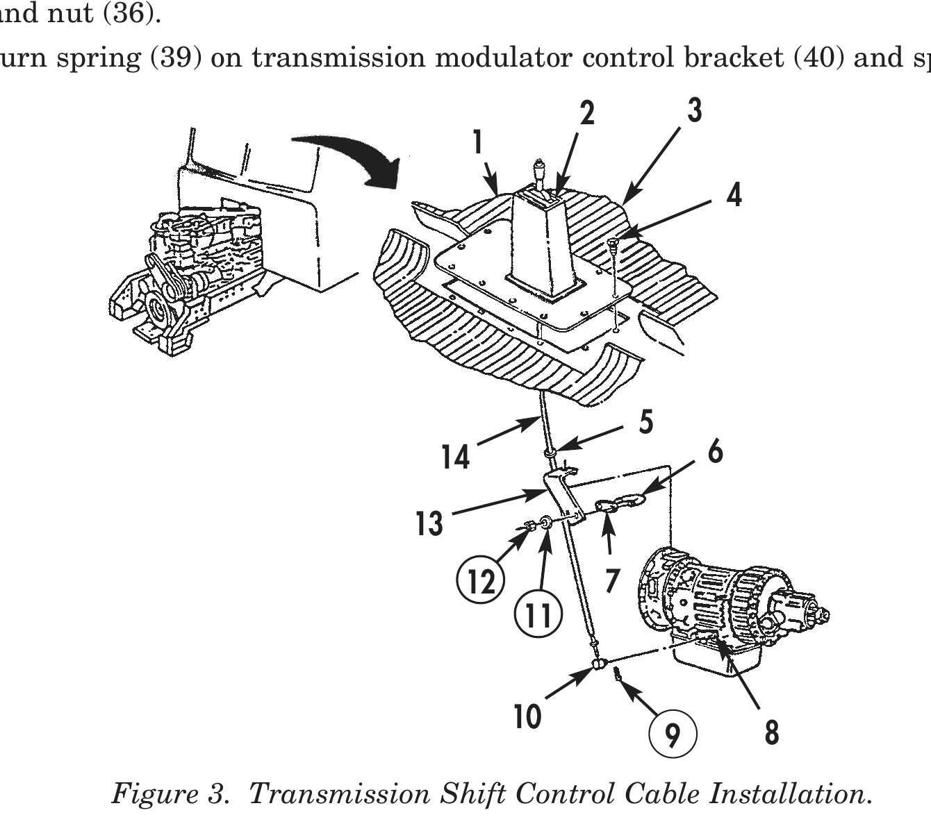
16. Install transmission floor shifter assembly (2) and floor pan access cover (1) to cab floor with ten floor pan access cover screws (4). Tighten screws (4) 15–20 lb-ft (20–27 N•m).
17. Position floor mat (3) around transmission floor shifter assembly (2) and floor pan access cover (1).
18. Install trunion (10) in transmission shift lever (8) with new trunion retaining pin (9).
19. Install transmission shift control cable assembly (14) to transmission shift control cable mounting bracket (13) with spacer plate (7), U-bolt (6), two new lockwashers (11), and new locknuts (12). Ensure grommet (5) is correctly positioned in U-bolt (6).
20. Install rear cooler hose bracket (17) to transmission (16) with rear cooler hose bracket washer (18) and screw (19).
21. Install middle cooler hose bracket (20) to oil pan (21) with middle cooler hose bracket screw (22).
22. Install front hose clamp (33) on cooler hose bracket (34) with front hose clamp screw (32) and nut (35).
23. Install positive battery cable (23), starter motor ground strap (28), and negative battery cable (25) on starter motor (24) with new starter motor terminal lockwasher (26) and nut (27).
24. Install ground strap (31) and starter motor ground strap (28) on engine (15) with new ground strap starwasher (29) and bolt (30).
25. Install transmission modulator control bracket (40) on engine (15) with two new transmission modulator control bracket lockwashers (41) and bolts (42).
26. Install transmission modulator control link (50) on transmission modulator control bracket (40) with U-bolt (43), spacer plate (44), two washers (45), and nuts (46).
27. Install transmission modulator control link (50) and washer (48) on fuel control lever (51) with new retaining pin (47).
28. Install accelerator link (49) on fuel control lever (51) accelerator link washer (37), return spring clip (38), and nut (36).
29. Install return spring (39) on transmission modulator control bracket (40) and spring clip (38). 2 3
14 6
12 7
9 8 Figure 3. Transmission Shift Control Cable Installation.
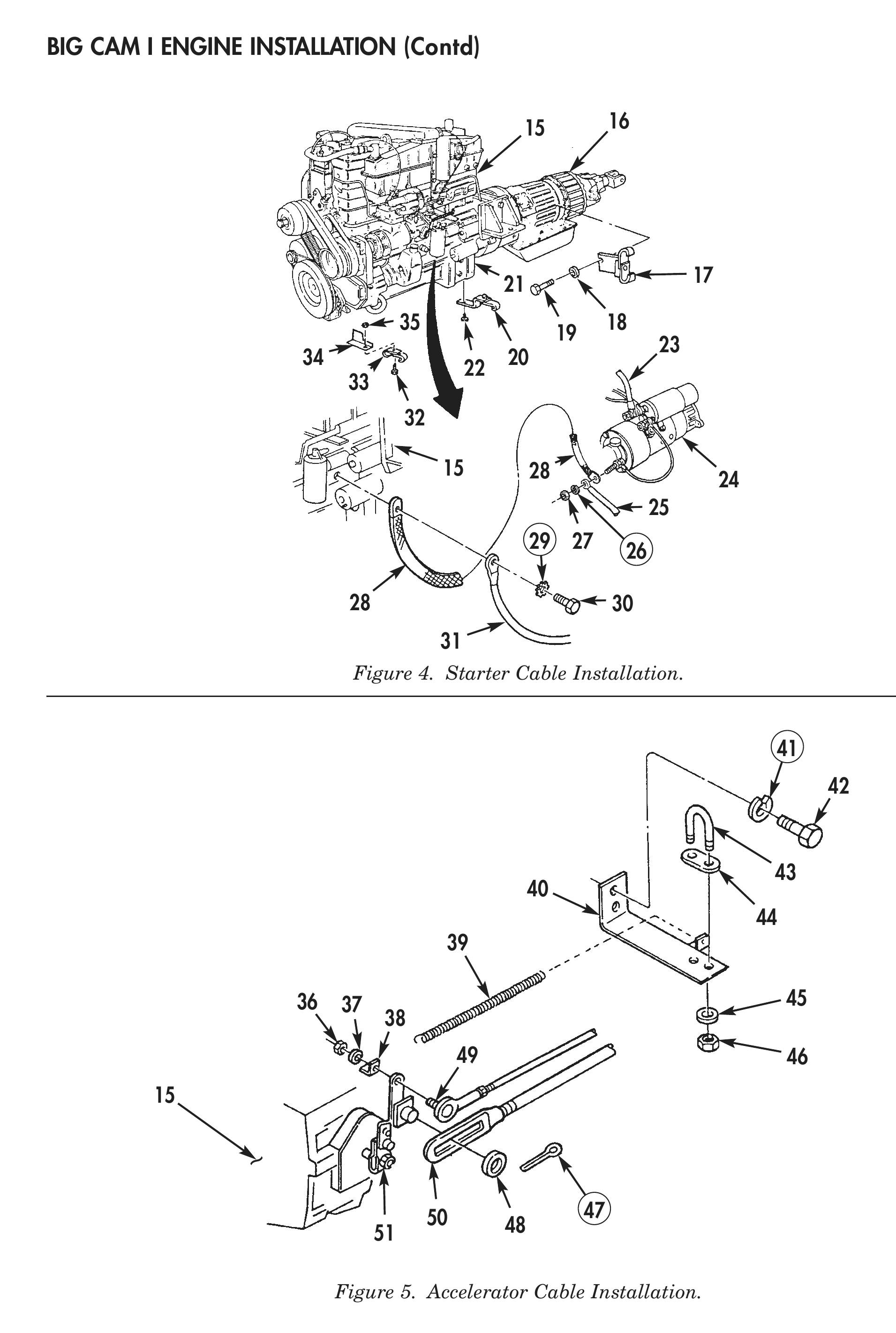
Figure 4. Starter Cable Installation.
Figure 5. Accelerator Cable Installation.
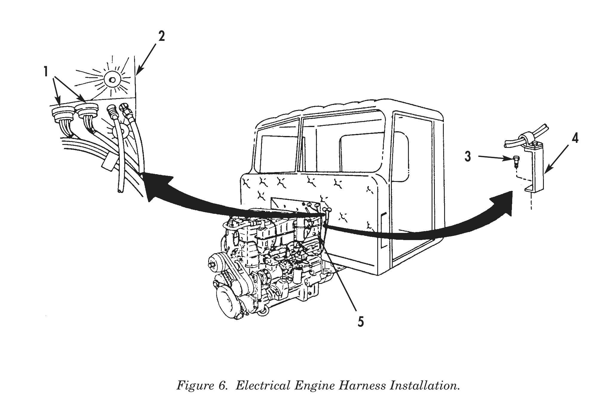
30. Connect engine harness electrical connectors (1) at firewall (2).
31. Install electrical harness bracket (4) on engine (5) with screw (3). Tighten screw (3) 15–20 lb-ft (20–27 N•m).
32. Connect air compressor line (6) to air compressor (7).
33. Connect fuel line (10) to fuel filter and damper (11).
34. Connect tachometer shaft assembly (15) to tachometer (14).
35. Install ether quick start kit bracket (8), on engine with two clamps (13) and (16) and bracket nut (17) and screw (12). Tighten nut (17) and screw (12) 15–20 lb-ft (20–27 N•m).
36. Install tachometer shaft assembly (15) on ether quick start kit bracket (8) with new plastic tie (9).
37. Install speedometer shaft assembly (22) on fuel return line (20) with new plastic tie (21).
38. Connect fuel return line (20) to fuel rail male branch tree (19).
39. Connect air compressor hose (23) to air compressor line (24).
40. Connect air compressor lines (24) and (25) to air compressor line T-adapter (18).
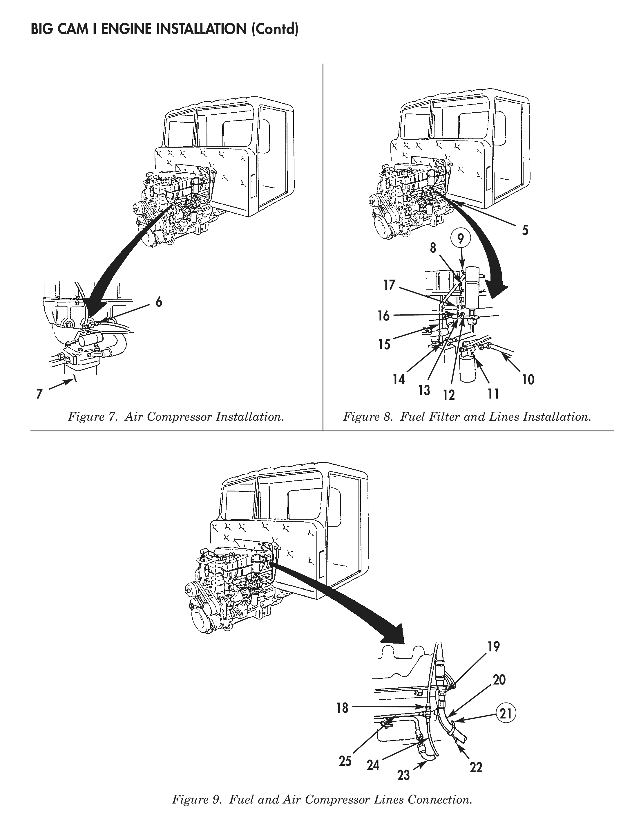
Figure 7. Air Compressor Installation. Figure 8. Fuel Filter and Lines Installation.
Figure 9. Fuel and Air Compressor Lines Connection.
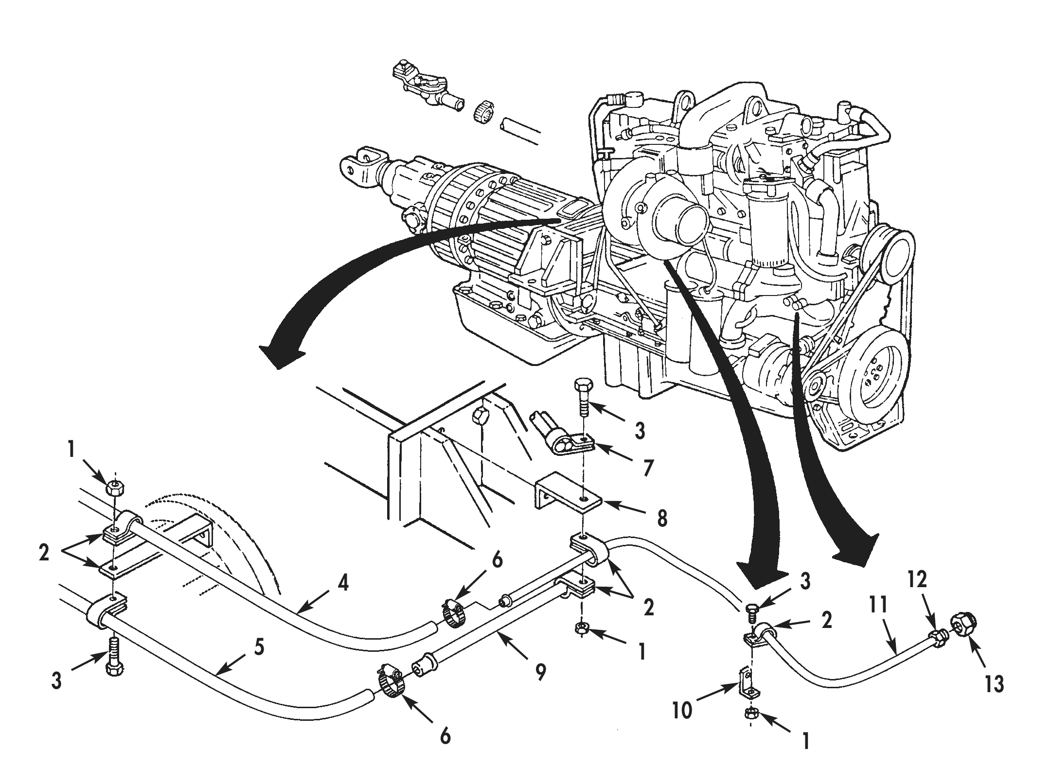
41. Position heater tube (11) and secure to fitting (13) using flare nut (12). Do not tighten flare nut (12).
42. Connect heater hose (4) to heater tube (11) and secure using clamp (6).
43. Connect heater hose (5) to heater tube (9) and secure using clamp (6).
44. Connect heater hose (15) to heater valve (14) and secure using clamp (6).
45. Secure heater hose (4), heater hose (5), bracket (8), bracket (10), and battery cable terminal (7) in three places using clamps (2) bolts (3) and nuts (1).
46. Tighten flare nut (12) to fitting (13).
2 6 4 3 12 2 11 5 1 3 9 6 1
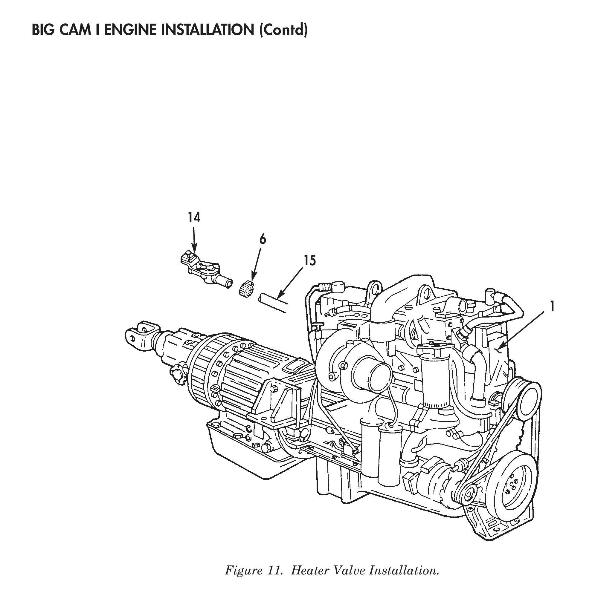
47. Loosen two lower alternator screws (1) retaining alternator (19) in position.
48. Install new alternator adjusting rod lockwasher (6), washer (5), alternator adjusting rod (9), alternator adjusting rod block (12), three alternator adjusting rod nuts (10) and two washers (11) as an assembly on engine (3) with alternator adjusting rod bolt (7).
49. Install alternator (19) to alternator adjusting rod block (12) with washer (13), nut (2), and alternator bolt (14). Do not tighten alternator bolt (14) at this time.
50. Install two new belts (8) on alternator pulley (15) and crankshaft pulley (4).
51. Using alternator adjusting rod nuts (10), adjust alternator (19) belt tension 110 lbs (50 kg).
52. Tighten two lower alternator nuts (17) and alternator adjusting rod nuts (10).
53. Install horn wire (TM 9-2320-283-20).
54. Install radiator and support rods (TM 9-2320-283-20).
55. Install grille shell (TM 9-2320-283-20).
56. Install fan (TM 9-2320-283-20).
57. Install upper radiator fan shroud (TM 9-2320-283-20).
58. Install radiator support brackets (TM 9-2320-283-20).
59. Install air cleaner (TM 9-2320-283-20).
60. Install turbocharger exhaust tube (TM 9-2320-283-20).
61. Install cooling system hoses (TM 9-2320-283-20).
62. Install power steering pump hydraulic lines (TM 9-2320-283-20).
63. Fill steering system to proper level (TM 9-2320-283-20).
64. Install transmission oil cooler lines (TM 9-2320-283-20).
65. Fill cooling system to proper level (TM 9-2320-283-20).
66. Fill engine crankcase to proper level (TM 9-2320-283-20).
67. Install hood (TM 9-2320-283-20).
68. Install fenders (TM 9-2320-283-20).
69. Install bumper and towing eyes (TM 9-2320-283-20).
70. Install brush guard and spotter mirrors (TM 9-2320-283-20).
71. Close air reservoir draincocks (TM 9-2320-283-20).
72. Install negative battery cable (20) on battery (23), and connect two negative battery cable clamps (21) on two negative battery cable posts (22).
73. Perform engine testing (WP 0047 00).
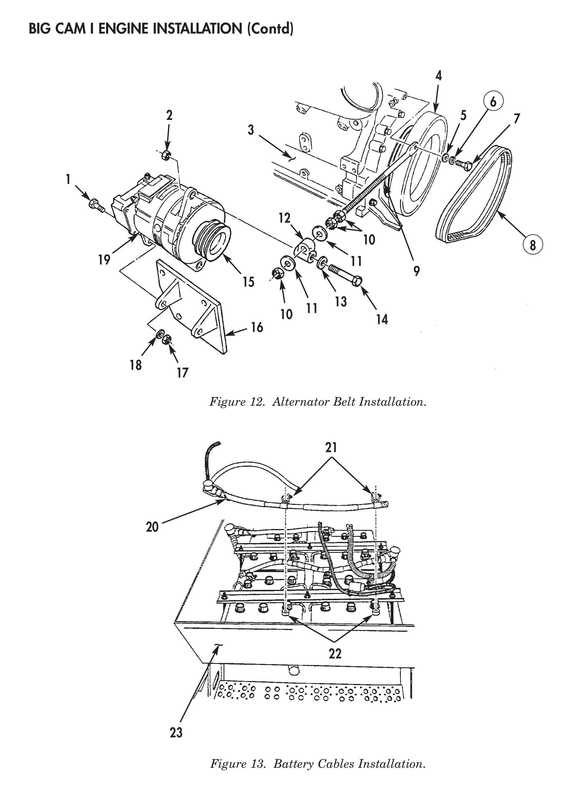
Figure 12. Alternator Belt Installation.
Figure 13. Battery Cables Installation.