AIR COMPRESSOR
TM 9-2815-225-34&P · Work Package 0031 00
DISASSEMBLY, CLEANING AND INSPECTION, ASSEMBLY
INITIAL SETUP
Tools and Special Tools                              Materials/Parts (Contd)
 General mechanic’s tool kit:                         Small O-ring (Item 9, Table 15, WP 0062 00)
    automotive (Item 1, WP 0061 00)                   Spring (Item 10, Table 15, WP 0062 00)
 Maintenance and repair shop equipment:               Thrust bearing
    automotive (Item 2, WP 0061 00)                     (Item 11, Table 15, WP 0062 00)
 Automotive maintenance and repair                    Four lockwashers
    supplemental set no. 2 (Item 3, WP 0061 00)         (Item 12, Table 15, WP 0062 00)
 Air compressor mounting plate                        Gasket (Item 13, Table 15, WP 0062 00)
    (Item 34, WP 0061 00)                             Two retaining rings
 Ball joint vise (Item 9, WP 0061 00)                   (Item 14, Table 15, WP 0062 00)
 Half coupling puller (Item 35, WP 0061 00)           Piston ring (Item 15, Table 15, WP 0062 00)
 Air compressor bushing mandrel                       Piston ring (Item 16, Table 15, WP 0062 00)
    (Item 36, WP 0061 00)                             Piston ring (Item 17, Table 15, WP 0062 00)
 Line bore gauge (Item 37, WP 0061 00)                Bushing (Item 18, Table 15, WP 0062 00)
 Press                                                Bearing (Item 19, Table 15, WP 0062 00)
 Mandrel (Item 39, WP 0061 00)                        Cap (Item 20, Table 15, WP 0062 00)

Materials/Parts                                      Equipment Condition
 Lubricating oil (Item 19, WP 0060 00)                Air compressor removed from engine
 Antiseize compound (Item 7, WP 0060 00)                (WP 0011 00).
 Large O-ring (Item 1, Table 15, WP 0062 00)
 Small O-ring (Item 2, Table 15, WP 0062 00)
 Spring (Item 3, Table 15, WP 0062 00)
 Spring (Item 4, Table 15, WP 0062 00)
 Four lockwashers
   (Item 5, Table 15, WP 0062 00)
 Gasket (Item 6, Table 15, WP 0062 00)
 Gasket (Item 7, Table 15, WP 0062 00)
 Large O-ring (Item 8, Table 15, WP 0062 00)
DISASSEMBLY
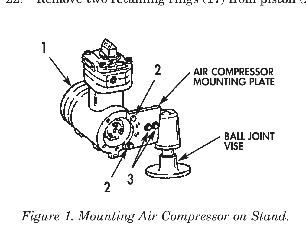
1. Install air compressor mounting plate on air compressor (1) with two bolts (2).
2. Install air compressor (1) and air compressor mounting plate on ball joint vise with two bolts (3).
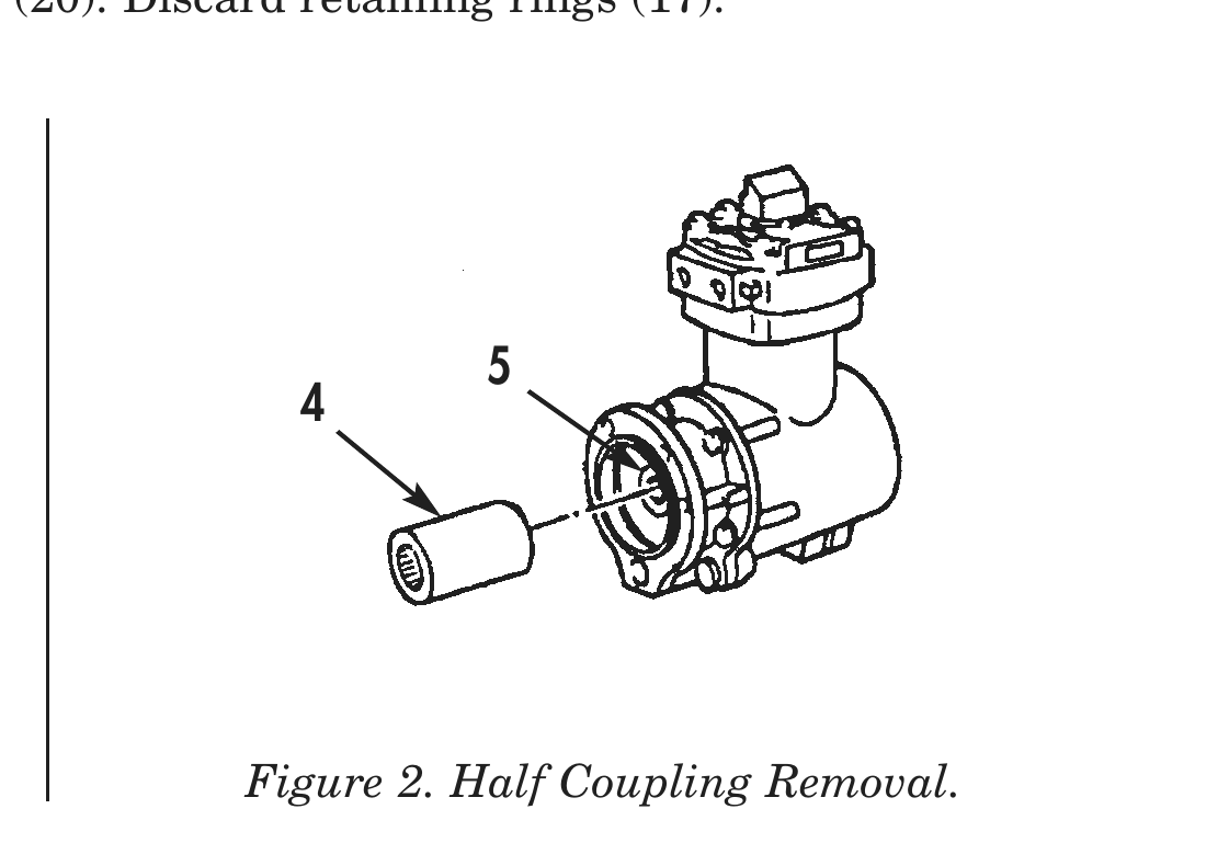
3. Using half coupling puller, remove half coupling (4) from crankshaft (5).
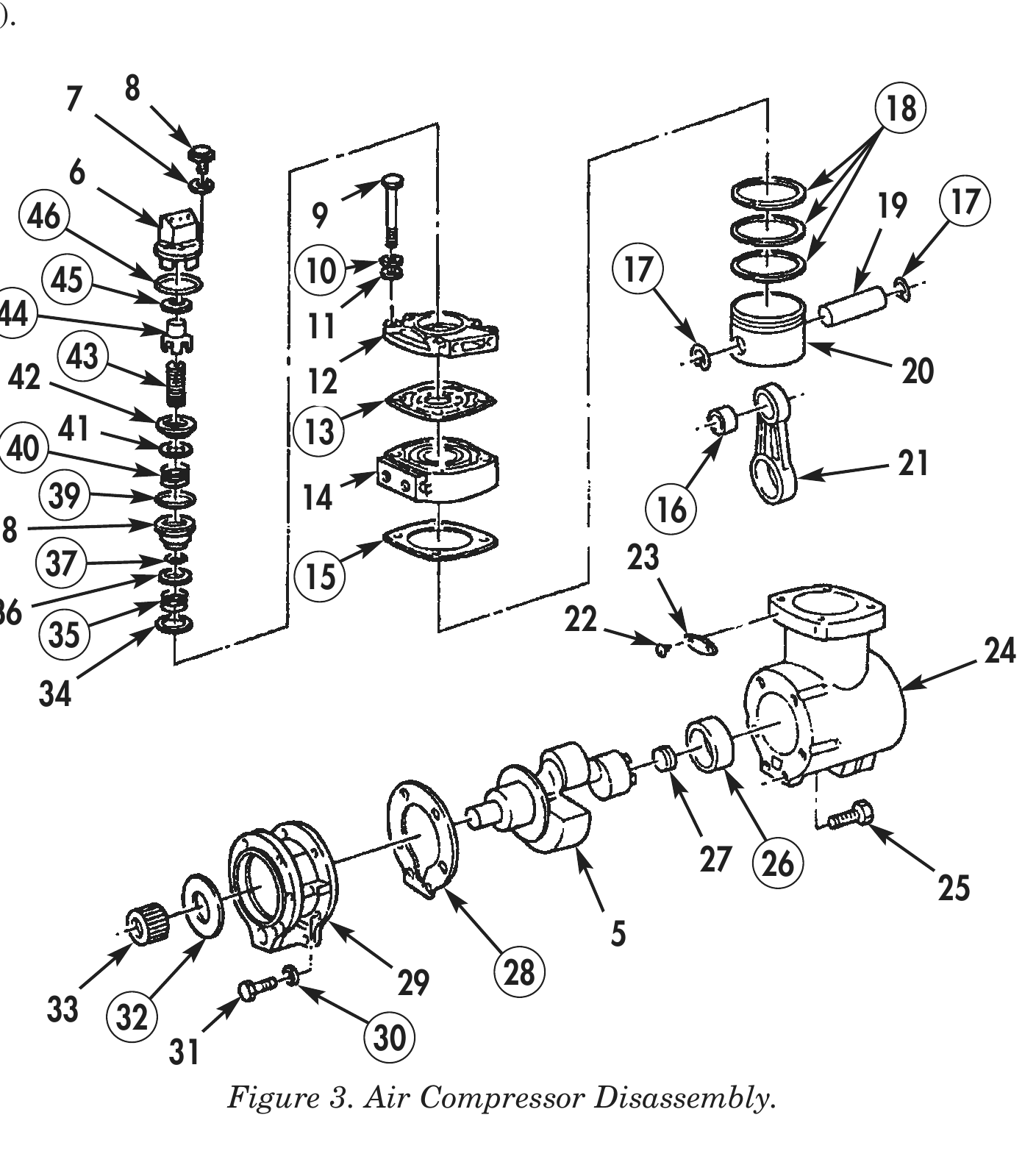
4. Remove two screws (8), two washers (7), valve body (6), cap (44), and spring (43) from cover (12). Discard cap (44) and spring (43).
5. Remove large O-ring (46) and small O-ring (45) from valve body (6). Discard large O-ring (46) and small O-ring (45).
6. Remove seat (42), valve (41), and spring (40) from cylinder head (14). Discard spring (40).
7. Remove four bolts (9), lockwashers (10), washers (11), cover (12), and gasket (13) from cylinder head (14). Discard lockwashers (10) and gasket (13).
8. Remove cylinder head (14) and gasket (15) from cylinder housing (24). Discard gasket (15).
9. Using press and mandrel, remove seat (38) from bottom of cylinder head (14).
10. Remove large O-ring (39) and small O-ring (37) from seat (38). Discard large O-ring (39) and small O-ring (37).
11. Remove disc (36), spring (35), and shim (34) from cylinder head (14). Discard spring (35).
12. Remove two screws (22) and plate (23) from cylinder housing (24).
13. Remove drive coupling (33) from crankshaft (5) if not previously removed.
14. Remove thrust bearing (32) from crankshaft (5). Discard thrust bearing (32).
15. Remove two screws (25) securing support (29) to cylinder housing (24).
16. Remove four screws (31), lockwashers (30), support (29), and gasket (28) from cylinder housing (24). Discard lockwashers (30) and gasket (28).
17. Rotate piston (20) 90° before or after top dead center.
18. Rotate crankshaft (5) while pulling out and remove crankshaft (5) from connecting rod (21) and cylinder housing (24).
19. Remove pipe plug (27) from crankshaft (5).
20. Using a ridge reamer, remove any ridge or carbon deposits from top of cylinder housing (24).
21. Remove piston (20) and connecting rod (21) out through top of cylinder housing (24).
22. Remove two retaining rings (17) from piston (20). Discard retaining rings (17).
2      AIR COMPRESSOR
MOUNTING PLATE
BALL JOINT
VISE
DISASSEMBLY (Contd)
23. Remove piston pin (19) and piston (20) from connecting rod (21).
24. Remove three piston rings (18) from piston (20). Discard piston rings (18).
25. Using press and mandrel, remove bushing (16) from connecting rod (21). Discard bushing (16).
26. Using press and air compressor bushing, remove bearing (26) from cylinder housing (24). Discard bearing (26).
7 8
46                       9                                        19    17

  45                     10                        17
44 11 43 20 42 12 41 13 40 21 39 14 16 37 23 36 22 35 24
27 26 29 28 33 32 31 30 Figure 3. Air Compressor Disassembly.
CLEANING AND INSPECTION
1. For general parts cleaning information, refer to CLEANING, WP 0051 00.
2. For general parts inspection information, refer to INSPECTION, WP 0051 00.
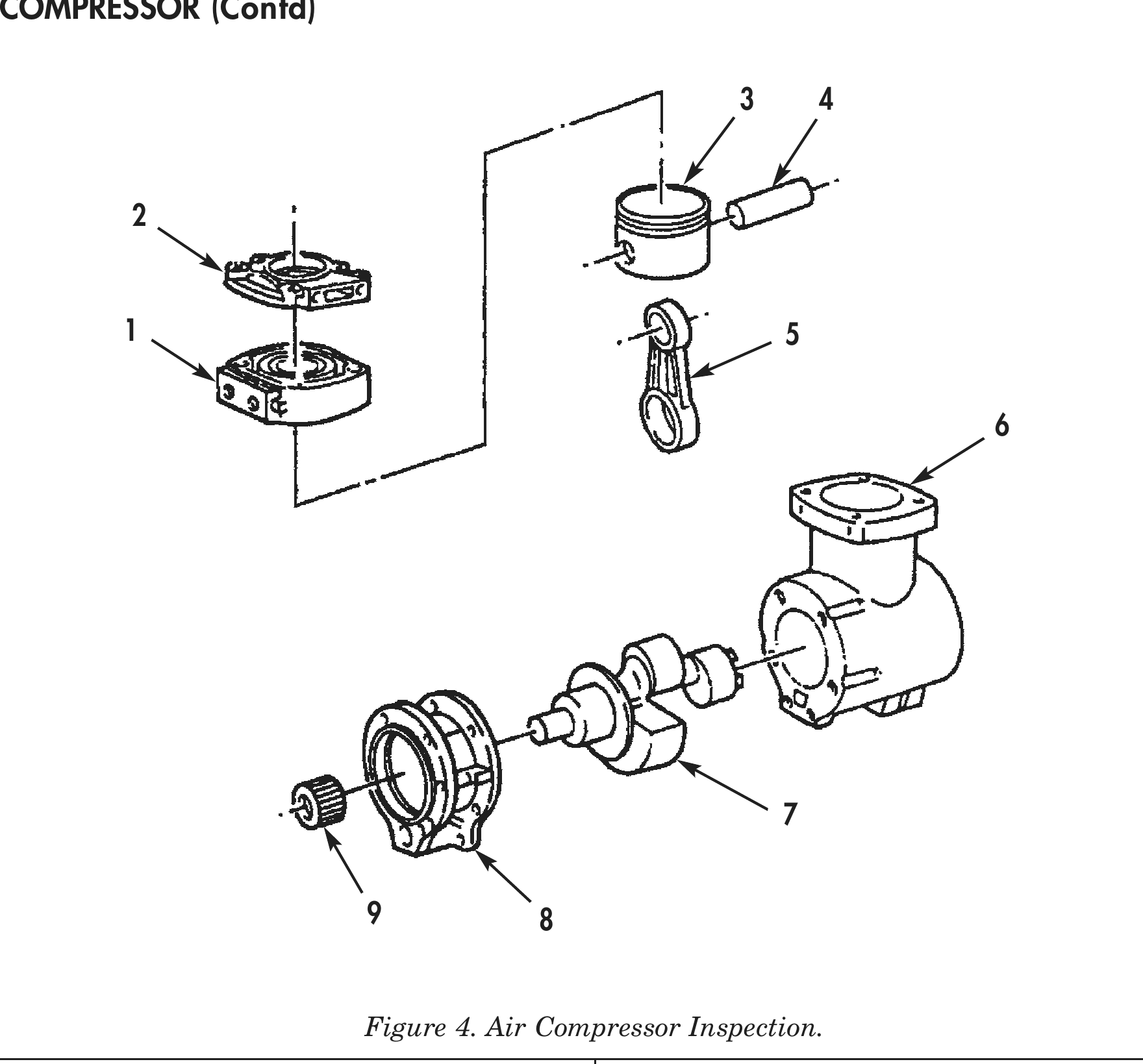
3. Inspect cylinder head (1) and cover (2) mating surfaces for scratches, scoring, cracks and pitting.
4. Inspect drive coupling (9) for chipped or stripped teeth, and cracks.
5. Inspect support (8) for cracks, scratches, and scores.
6. Inspect connecting rod (5) inside diameters for scratches, scoring and cracks.
7. Using straight edge and feeler gauge, measure connecting rod (5) for bend and twist. Discard connecting rod (5) if bend is greater than 0.002 in. (0.508 mm) maximum, and twist maximum is greater than 0.004 in. (0.102 mm).
8. Using inside micrometer, measure connecting rod (5) crankshaft end inside diameter. Maximum diameter is 1.935 in. (49.149 mm). Discard connecting rod (5) if maximum diameter is exceeded.
9. Inspect cylinder housing (6) for scratches, scoring, and cracks.
10. Using a line bore gauge, measure cylinder housing (6) bore inside diameter and bore out-of-round dimensions. Maximum cylinder housing (6) inside bore diameter allowed is 3.6285 in. (9.2164 cm). Maximum cylinder housing (6) bore out-of-round dimension allowed is 0.0015 in. (0.0381 mm). Discard cylinder housing (6) if either measurement is over limit.
11. Hone bore of cylinder housing (6) to remove glaze.
12. Inspect piston (3) for scoring, pitting, chips, or cracks.
13. Using inside micrometer, measure piston pin (3) bore. Replace piston (3) if piston pin bore is above 0.6885 in. (17.4879 mm).
14. Using micrometer or equivalent, measure piston pin (4) outside diameter. Replace piston pin (4) if outside diameter is above 0.6876 in. (17.4625 mm).
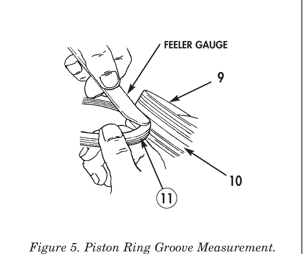
15. Position a new piston ring (11) in piston ring groove (10). Using a feeler gauge, check the clearance between piston ring (11) and piston ring groove (10). Discard piston (9) if clearance is more than 0.004 in. (0.1016 mm).
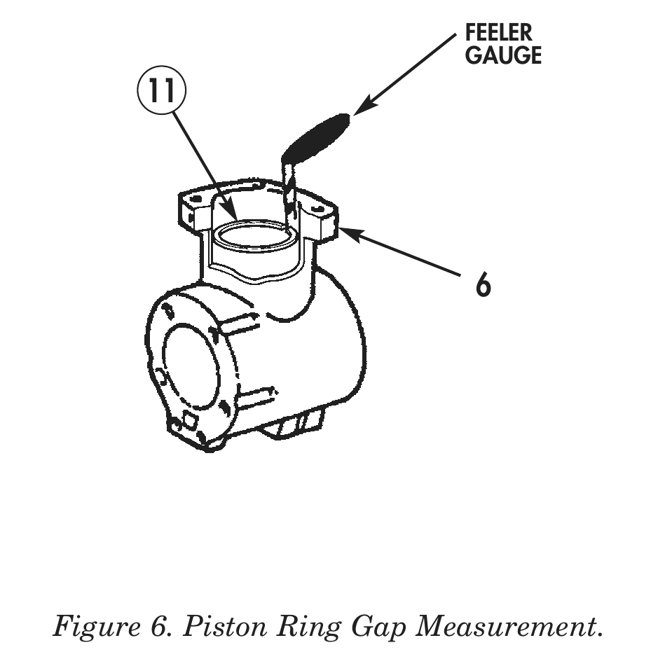
16. Position a new piston ring (11) in top of cylinder housing (6) bore. Using a feeler gauge, measure piston ring (11) end gap. Piston ring (11) gap must be between 0.010–0.020 in. (0.254–0.508 mm). If correct gap cannot be obtained, replace piston ring (11).
3 4
1 5
9 8
FEELER
GAUGE
FEELER GAUGE
CLEANING AND INSPECTION (Contd)
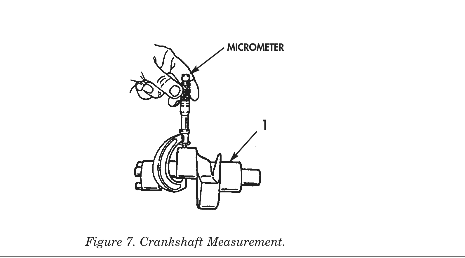
17. Using micrometer, measure all crankshaft (1) journals. Refer to table 1 for crankshaft (1) journal measurements. Replace crankshaft (1) if any journal is beyond specifications.
Table 1. Crankshaft Journal Specifications.
 CRANKSHAFT JOURNAL               MINIMUM                     MAXIMUM                 WEAR LIMIT
Front Support Journal      1.872 in. (4.755 cm)        1.873 in. (4.757 cm)    1.871 in (4.752 cm)
Half Coupling Journal      1.003 in. (2.548 cm)        1.0035 in. (2.549 cm)              —
Rear Coupling Journal      1.872 in. (4.755 cm)        1.873 in. (4.757 cm)    1.933 in. (4.910 cm)
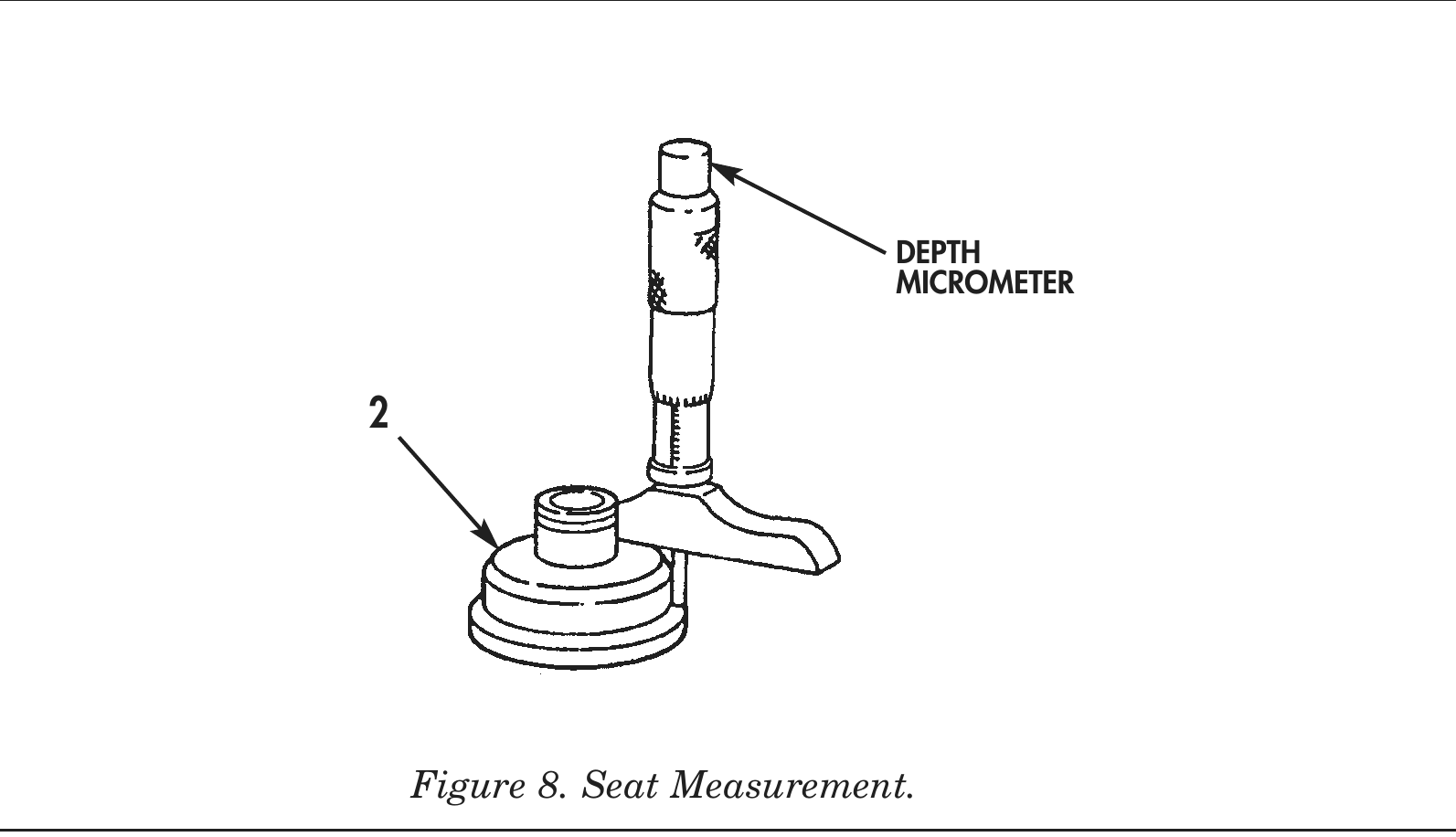
18. Using depth micrometer, measure seat (2) height. Seat height minimum is 0.485 in. (12.319 mm). Discard seat (2) if below minimum.
19. Using depth micrometer, measure height of seating area on seat (2). Seating area height minimum is 0.270 in. (6.858 mm). Discard seat (2) if below minimum.
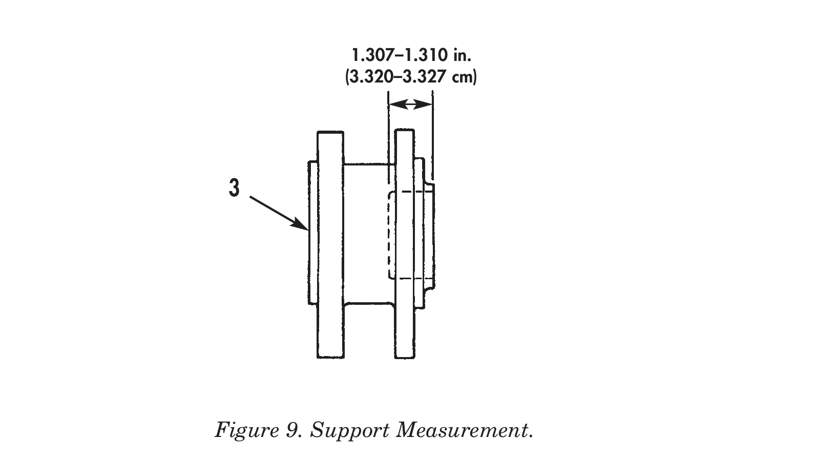
20. Using depth micrometer, measure support thrust flange (3) depth. Support (3) thrust flange should be 1.307–1.310 in. (3.320–3.327 cm).
MICROMETER
DEPTH
MICROMETER
1.307–1.310 in. (3.320–3.327 cm)
ASSEMBLY
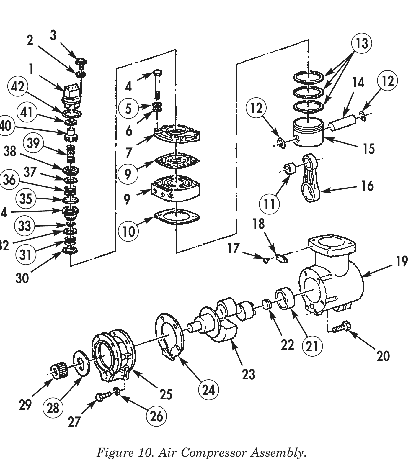
1. Using press and mandrel, install new bushing (11) in connecting rod (16).
2. Using press and mandrel, install new bearing (21) in cylinder housing (19).
3. Install piston (15) on connecting rod (16) with piston pin (14).
4. Install two new retaining rings (12) in piston (15).
5. Apply lubricating oil to three new piston rings (13) and install on piston (15).
6. Stagger piston rings (13) gap 180° apart and ensure they are not positioned over piston pin bore. Install ring compressor on piston (15) and compress piston rings (13).
7. Position piston (15) with connecting rod (16) attached, in cylinder housing (19) bore. Using hammer with wood handle or equivalent, install connecting rod (16) and piston (15) in cylinder housing (19) by tapping piston (15) with wood end of hammer.
8. Install pipe plug (22) in crankshaft (23).
9. Rotate piston (15) 90° before or after top dead center in cylinder housing (19). To allow for crankshaft (23) installation.
10. Apply lubricating oil to crankshaft (23), connecting rod (16), bearing (21), and cylinder housing (19).
11. Rotate crankshaft (23) while pushing in to install crankshaft (23) in connecting rod (16) and cylinder housing (19).
12. Install new gasket (24) and support (25) on crankshaft (23) and cylinder housing (19) with six new lockwashers (26) and screws (27). Tighten screws (27) 30–35 lb-ft (41–47 N•m).
13. Apply lubricating oil to new thrust bearing (28) and install on crankshaft (23).
14. Apply lubricating oil to half coupling (29). Using press, install half coupling (29) on crankshaft (23).
ASSEMBLY (Contd)
15. Install plate (18) on cylinder housing (19) with two screws (17).
16. Apply lubricating oil to new large O-ring (35) and new small O-ring (33) and install on seat (34).
17. Install disc (32) on seat (34).
18. Install shim (30), new spring (31), seat (34), with disc (32) attached, in cylinder head (9).
19. Install new spring (36), valve (37), and seat (38) in cylinder head (9).
20. Install new gasket (10), cylinder head (9), new gasket (8), and cover (7) on cylinder housing (19) with four washers (6), new lockwashers (5), and bolts (4). Tighten bolts (4) 15–19 lb-ft (20–26 N•m).
21. Apply lubricating oil to new large O-ring (42) and and install on valve body (1).
22. Apply lubricating oil to new small O-ring (41) and install on valve body (1).
23. Install new spring (39), new cap (40), and valve body (1) on cover (7) with two washers (2) and screws (3). Tighten screws (3) 96–132 lb-in (11–15 N•m).
2 3
42                      4                                         14    12

  41                    5                          12
40 6 39 15 38 7 37 9 36 16 35 9 11 33 18 32 17 31 19
22 21 25 24 29 28 27 26
ASSEMBLY (Contd)
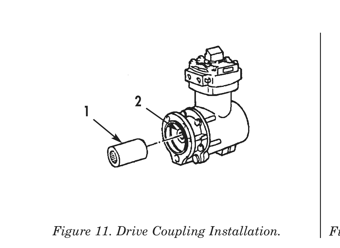
24. Install drive coupling (1) on half coupling (2) if not previously removed.
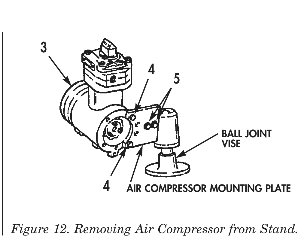
25. Remove two bolts (5), air compressor mounting plate, and air compressor (3) from ball joint vise.
26. Remove two bolts (4) and air compressor (3) from air compressor mounting plate.
27. For air compressor installation, refer to WP 0042 00.
BALL JOINT
VISE
4   AIR COMPRESSOR MOUNTING PLATE
END OF WORK PACKAGE