BIG CAM III ENGINE INSTALLATION
TM 9-2815-225-34&P · Work Package 0048 00
INITIAL SETUP
Tools and Special Tools                            Personnel Required
 General mechanic’s tool kit: automotive            Three assistants
    (Item 1, WP 0061 00)
 Maintenance and repair shop equipment:            Equipment Condition
    automotive (Item 2, WP 0061 00)                 Horn wire removed (TM 9-2320-283-20)
 Lifting sling (Item 42, WP 0061 00)                Grille shell removed (TM 9-2320-283-20)
 Lifting bracket (Item 43, WP 0061 00)              Fenders removed (TM 9-2320-283-20)
 Tilt sling (Item 67, WP 0061 00)                   Upper radiator fan shroud removed
                                                      (TM 9-2320-283-20)
Materials/Parts                                     Steering system to proper level removed
 Starter positive terminal lockwasher                 (TM 9-2320-283-20)
   (Item 1, Table 29, WP 0062 00)                   Transmission oil cooler lines removed
 Six air cleaner housing locknuts                     (TM 9-2320-283-20)
   (Item 2, Table 29, WP 0062 00)                   Air reservoir draincocks opened
 Two hood hinge locknuts                              (TM 9-2320-283-20)
   (Item 3, Table 29, WP 0062 00)                   Bumper and towing eyes removed
 Four air cleaner housing bracket locknuts            (TM 9-2320-283-20)
   (Item 4, Table 29, WP 0062 00)                   Brush guard and spotter mirrors removed
 Four radiator support rod locknuts                   (TM 9-2320-283-20)
   (Item 5, Table 29, WP 0062 00)
 Air cleaner element
   (Item 6, Table 29, WP 0062 00)
 Two radiator crossmember mount locknuts
   (Item 7, Table 29, WP 0062 00)
 Starter ground terminal lockwasher
   (Item 8, Table 29, WP 0062 00)
 Two transmission modulator clamp locknuts
   (Item 9, Table 29, WP 0062 00)
 Accelerator rod locknut
1. Attach two lifting brackets, lifting sling, and lifting device to engine (4).
2. Using lifting device and lifting sling, lower engine (4) on frame (1). Ensure that engine and transmission are properly aligned and there is proper clearance between frame (1) and alternator (11) and between frame (1) and power steering pump (5).
3. Install transmission (12) to flywheel housing (21) with twelve bolts (13). Tighten bolts (13) 16 lb-ft (21 N•m).
4. Install engine brackets (3) on frame (1) with four bolts (2), washers (15), insulators (16), and nuts (14). Tighten nuts (14) 130–166 lb-ft (176–225 N•m).
5. Install front engine crossmember mount (8) on frame (1) with two bolts (9), four washers (6), two insulators (7), and nuts (10). Tighten nuts (10) 130–166 lb-ft (176–225 N•m).
6. Remove lifting sling and lifting device from engine lifting brackets (18) and remove transmission jack from transmission (12).
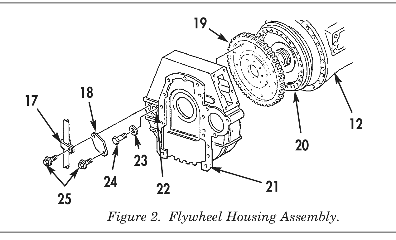
7. Install flywheel (19) on torque converter (20) with twelve bolts (24) and washers (23). Tighten bolts (24), 19–21 lb-ft (26–29 N•m).
8. Install P-clamp (17) and flywheel bolt access cover (18) on flywheel housing (21) with two screws (25).
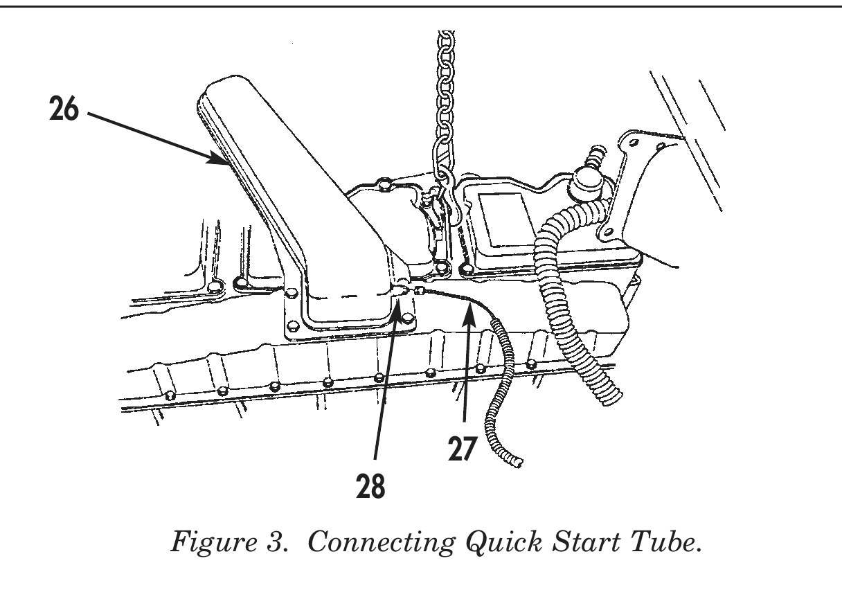
9. Connect ether quick-start tube (27) to atomizer (28) on intake manifold (26).
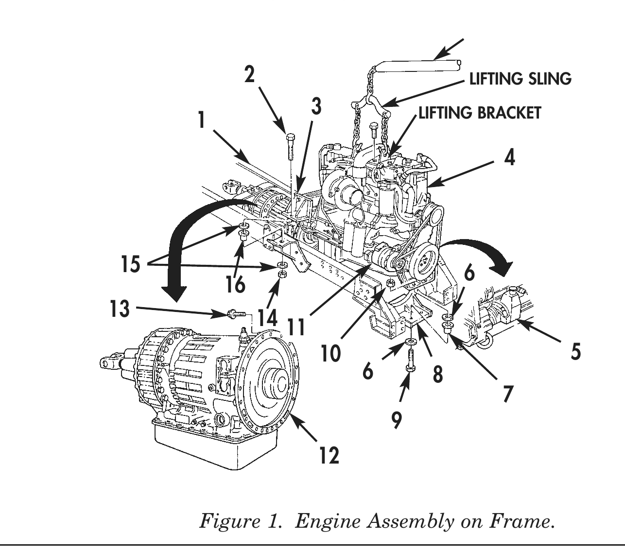
2                                     LIFTING SLING
3                 LIFTING BRACKET
15 6 13 14 11 10 5 6 8
24 21 Figure 2. Flywheel Housing Assembly.
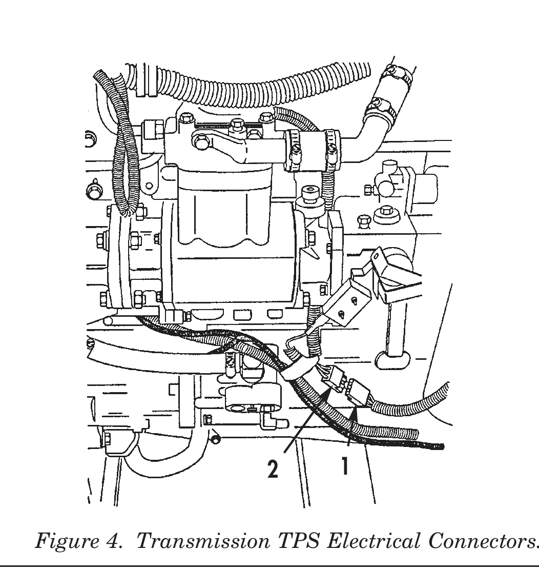
10. Connect transmission TPS harness electrical connector (2) to vehicle TPS harness electrical connector (1).
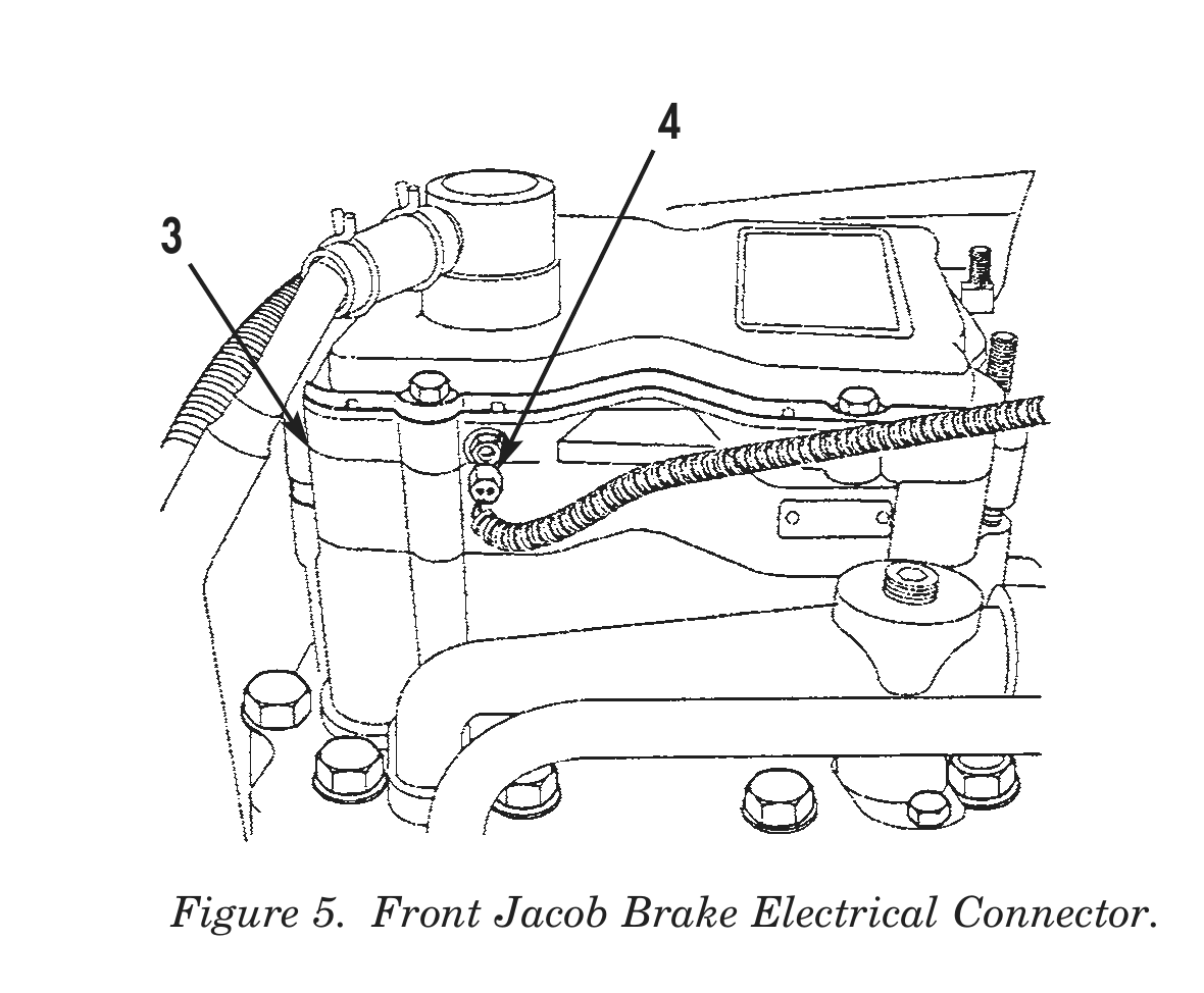
11. Connect front (4), middle (5), and rear (6) jacob brake electrical connectors to cylinder heads (3).
12. Connect jacob brake electrical connector (7) to engine harness electrical connector (8).
2 1
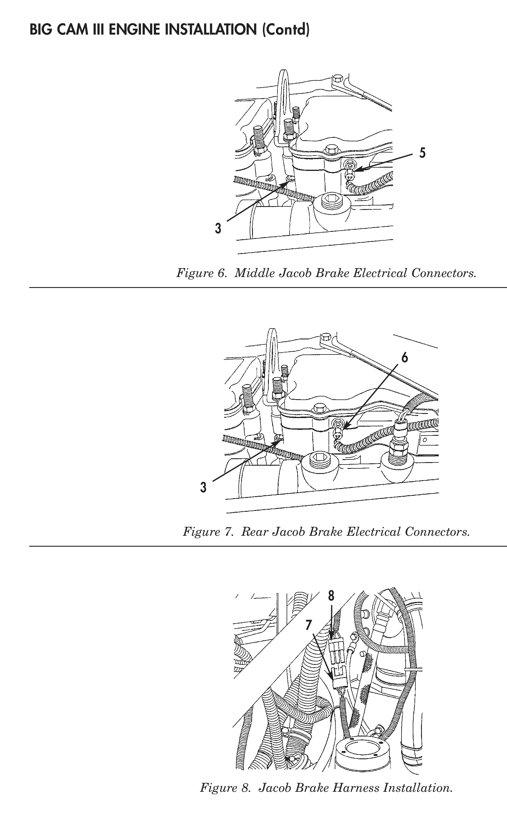
Figure 6. Middle Jacob Brake Electrical Connectors.
Figure 7. Rear Jacob Brake Electrical Connectors.
Figure 8. Jacob Brake Harness Installation.
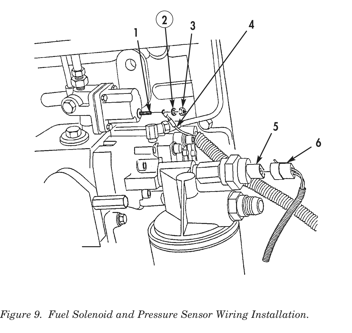
13. Connect fuel pump pressure sensor electrical connector (6) to fuel pump pressure sensor (5).
14. Install fuel solenoid electrical harness lead (4) on fuel solenoid (1) with fuel solenoid terminal lockwasher (2) and nut (3).
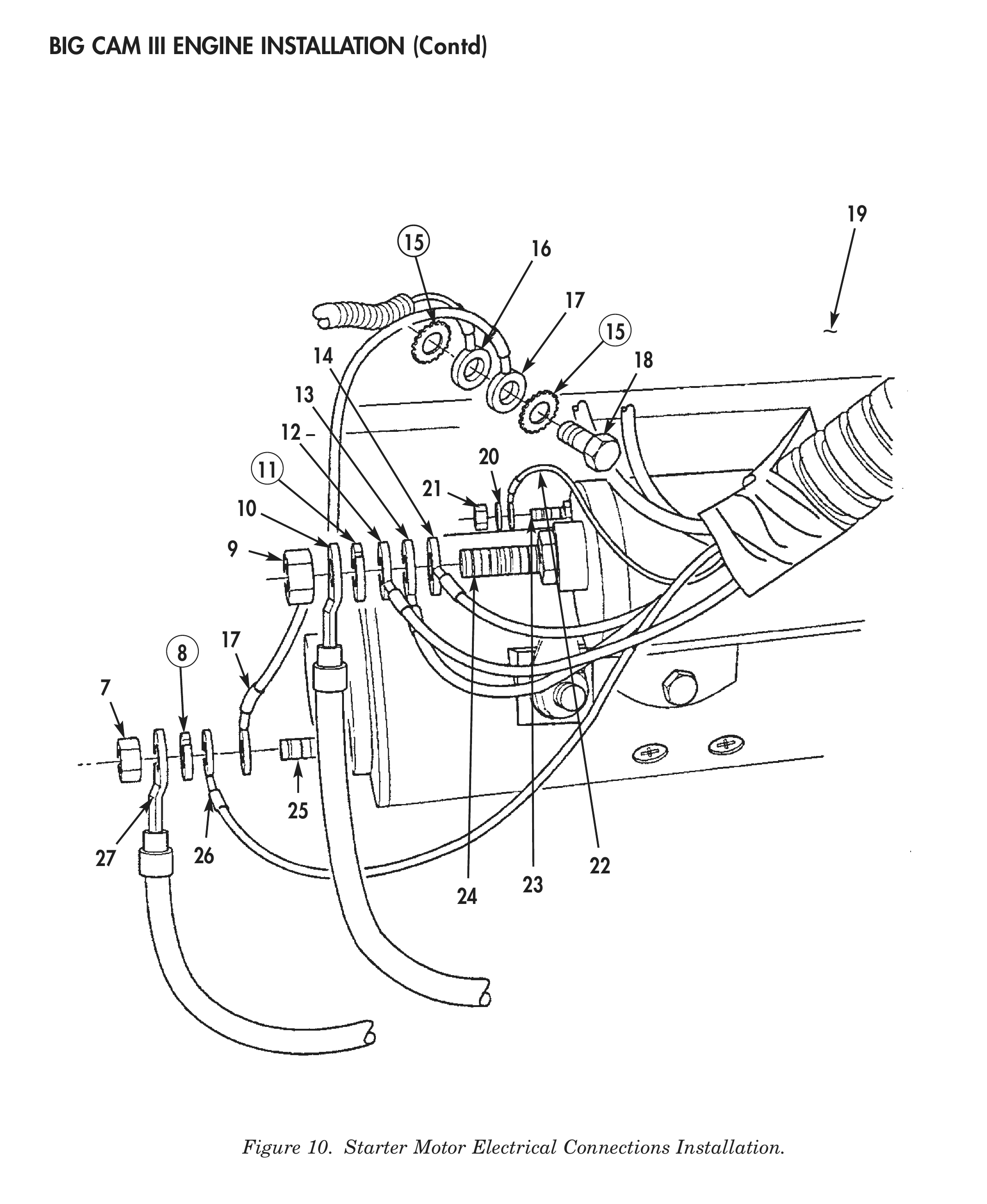
15. Install A/C electrical harness ground lead (16) and ground jumber cable (17) on engine (19) with two new A/C electrical harness ground lead starwashers (15), and screw (18).
16. Install battery ground cable (27), starter electrical harness lead no. 83 (26) and ground jumber cable (17) on starter ground terminal (25) with new starter ground terminal lockwasher (8) and nut (7).
17. Install battery positive cable (10) and three starter electrical harness leads no. 202 (12), no. 82 (13), and no. 421 (14) on starter positive terminal (24) with new starter positive terminal lockwasher (11) and nut (9).
18. Install starter electrical harness lead no. 74 (22) on starter S-terminal (23) with starter S-terminal lockwasher (20) and nut (21).
2 4
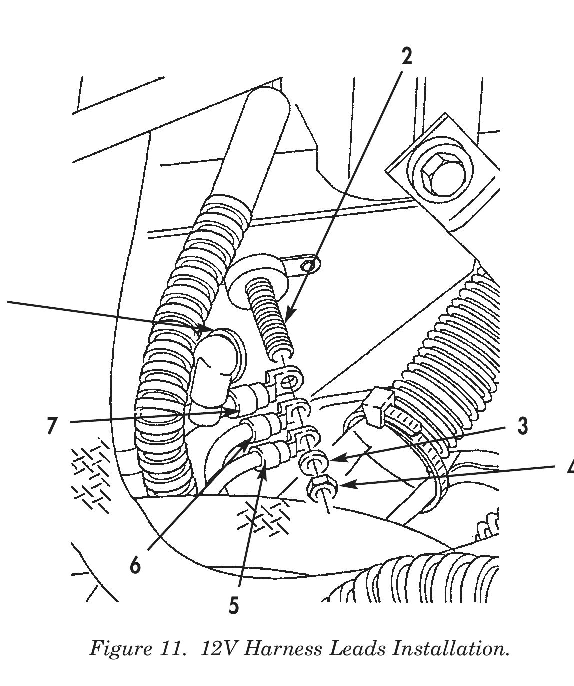
19. Install 12V power lead (7) and two engine harness leads (5) and (6) on 12V power stud (2) with 12V power stud washer (3), nut (4), and grommet (1).
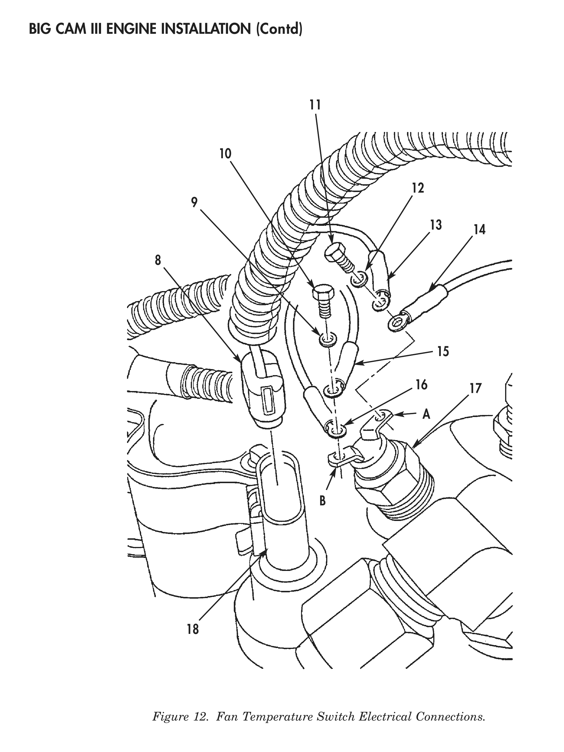
20. Install pressure harness lead (16) and fan solenoid lead (15) on fan temperature switch (17) terminal B with fan temperature switch washer (9) and screw (10).
21. Install pressure harness lead (13) and engine harness lead (14) on fan temperature switch (17) terminal A with fan temperature switch washer (12) and screw (11).
22. Connect temperature sensor electrical connector (8) to temperature sensor (18).
7 3
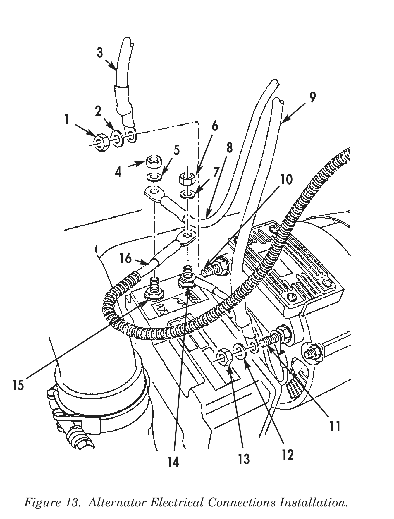
23. Install engine electrical harness transformer/rectifier negative lead (16) on alternator transformer/rectifier negative terminal (14) with alternator terminal washer (7) and nut (6).
24. Install engine electrical harness transformer/rectifier positive lead (8) on alternator transformer/rectifier positive terminal (15) with alternator terminal washer (5) and nut (4).
25. Install engine electrical harness negative lead (3) on alternator negative terminal (10) with alternator terminal washer (2) and nut (1).
26. Install engine electrical harness positive lead (9) on alternator positive terminal (11) with alternator terminal washer (12) and nut (13).
27. Install two drive belts (21) on alternator (22), drive pulley (25), and crankshaft pulley (26).
28. Tighten jamnut (17) on adjusting rod (24) until tension on drivebelts (21) is 110 lbs (50 kg).
29. Tighten jamnut (23).
30. Tighten two alternator mounting bracket nuts (20) (hidden) and screws (19).
1 6 5 8 4 7
13 12
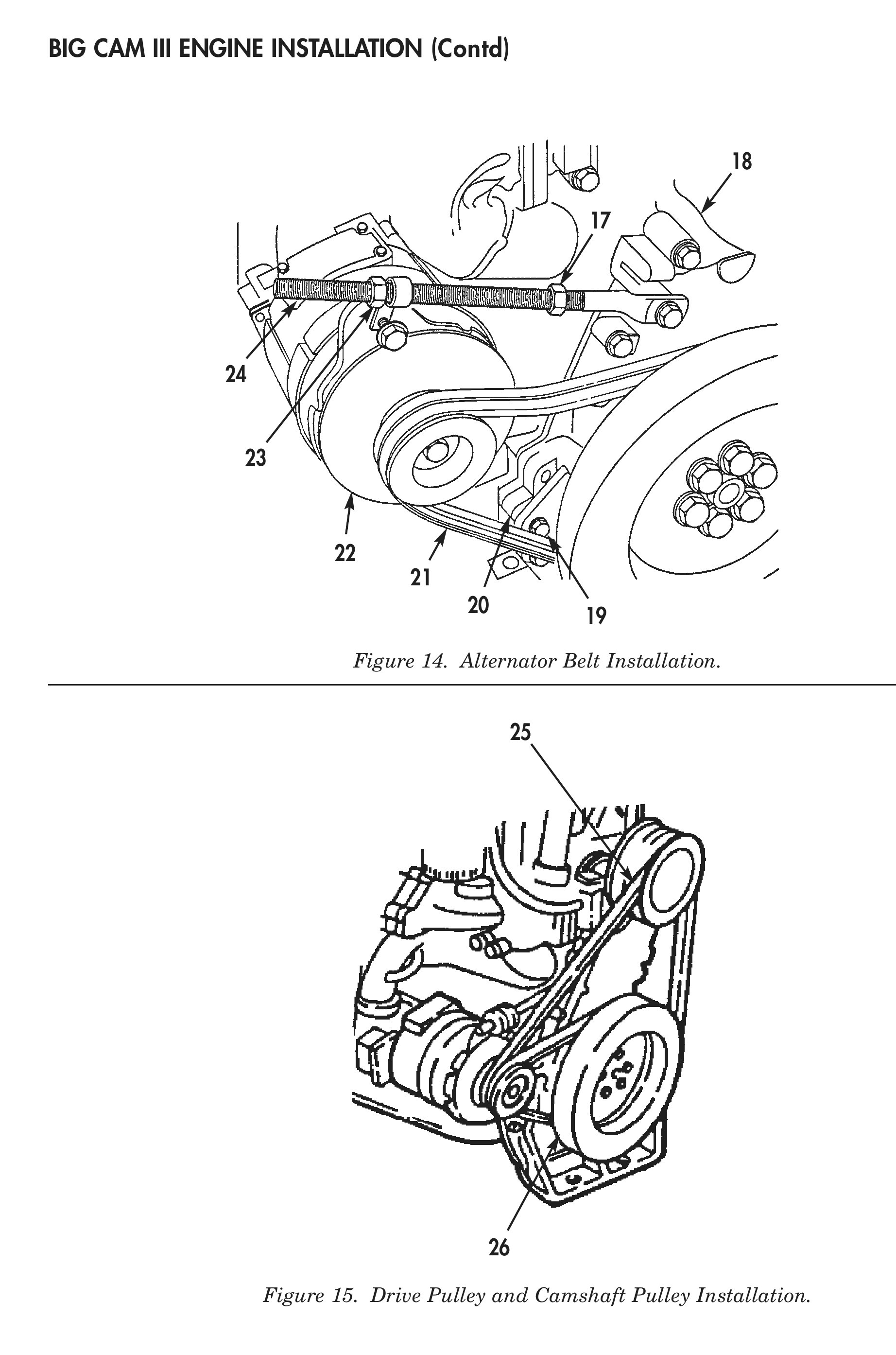
Figure 14. Alternator Belt Installation.
Figure 15. Drive Pulley and Camshaft Pulley Installation.
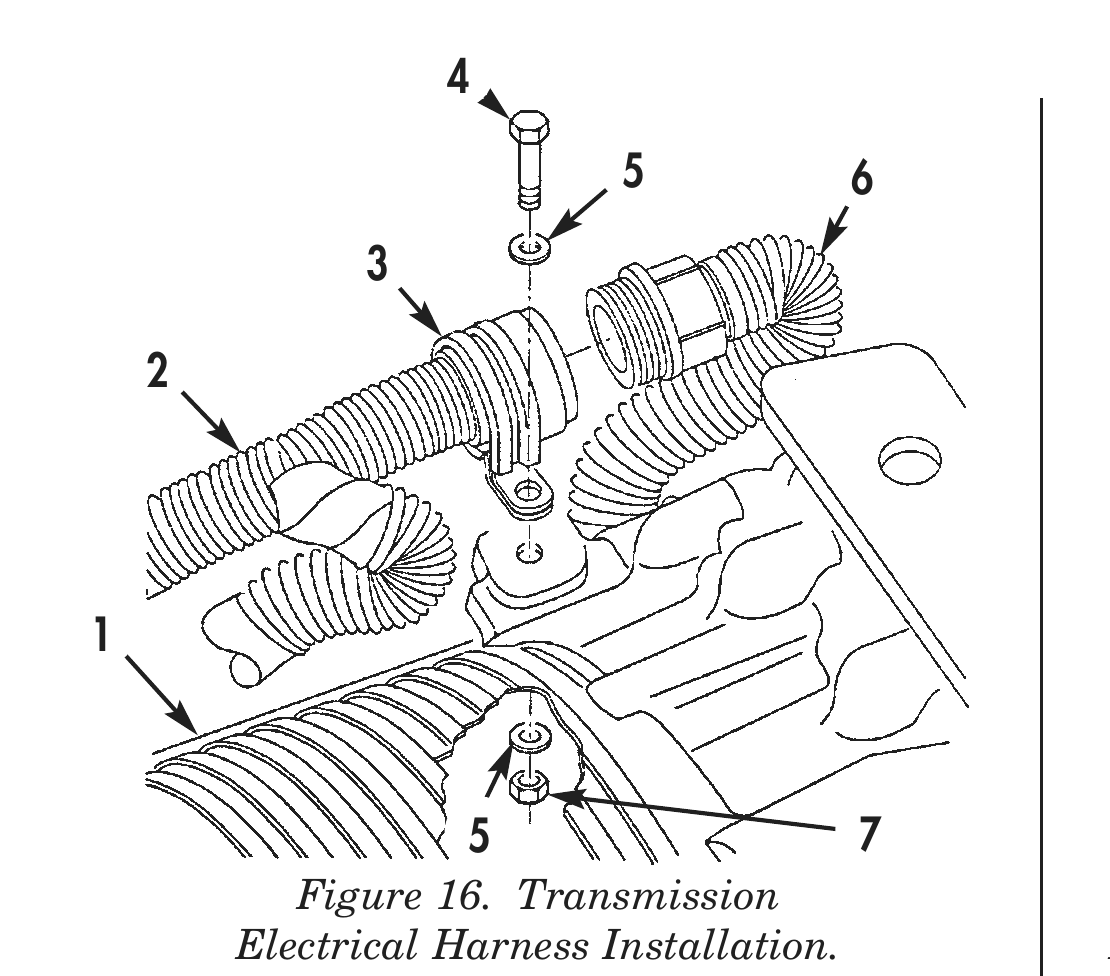
31. Connect control valve module electrical harness (6) to transmission electrical harness (2).
32. Install transmission electrical harness (2) on transmission (1) with transmission electrical harness clamp (3), two washers (5), screw (4), and nut (7).
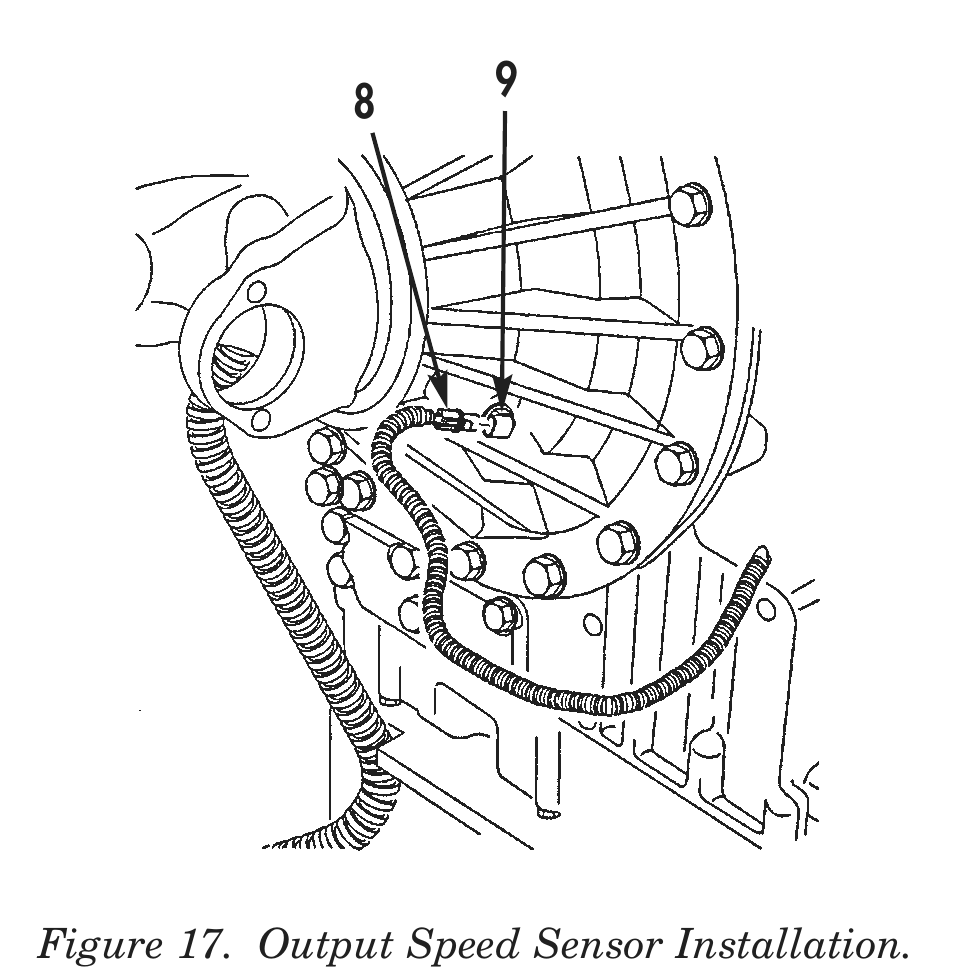
33. Connect output speed sensor electrical connector (8) to output speed sensor (9).
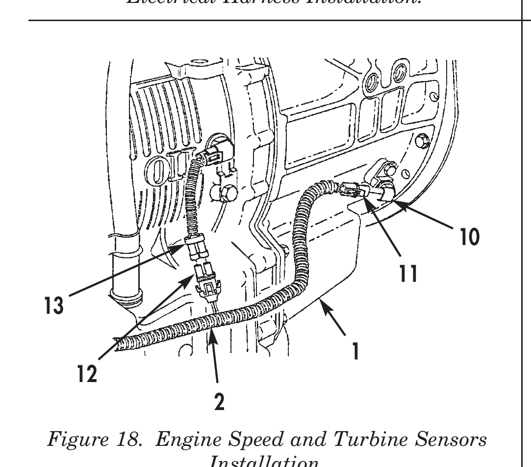
34. Connect turbine speed sensor electrical connector (12) on turbine speed sensor jumper harness (13).
35. Connect engine speed sensor electrical connector (11) to engine speed sensor (10).
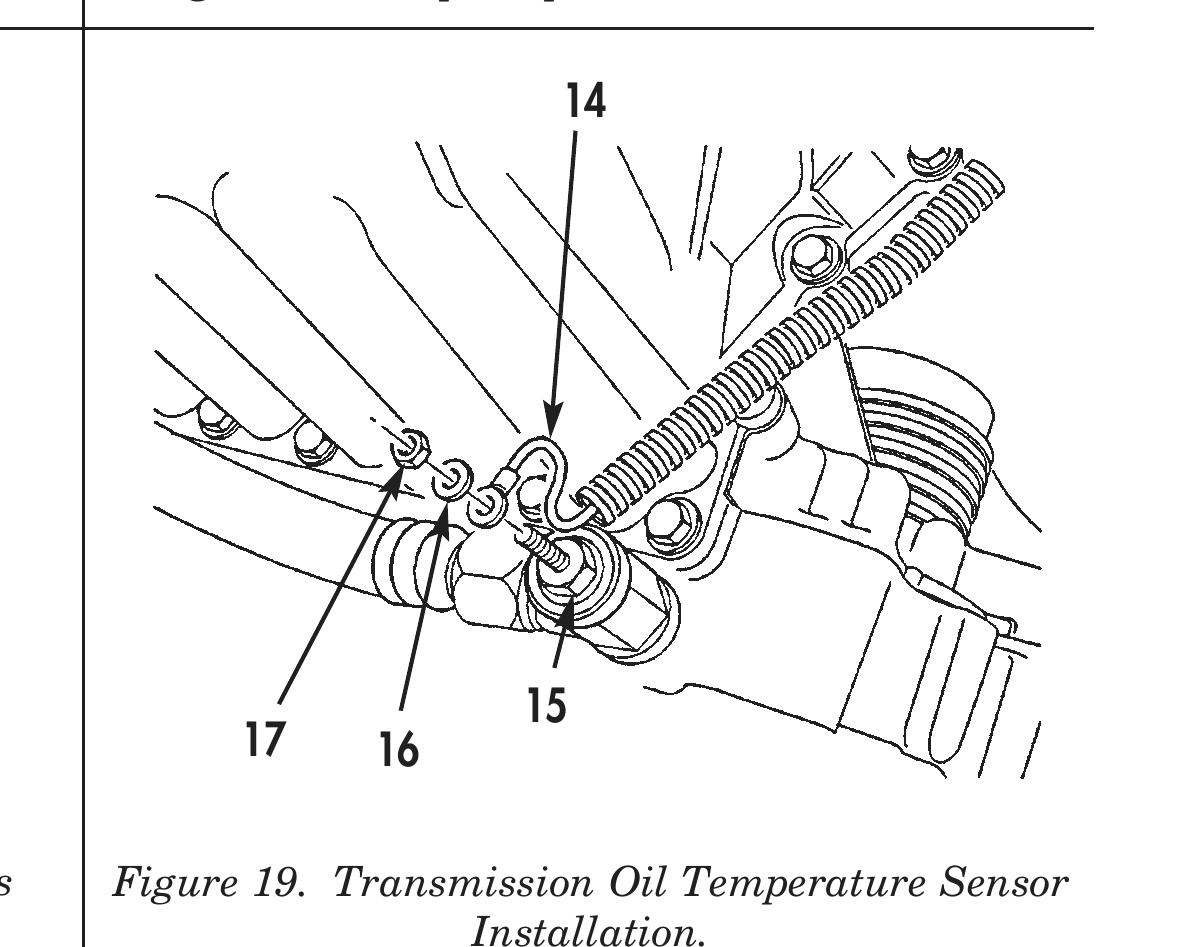
36. Install transmission oil temperature sensor electrical connector (14) on transmission oil temperature sensor (15) with transmission oil temperature sensor electrical connector washer (16) and nut (17).
4 9 5 6
5 Figure 16. Transmission Electrical Harness Installation.
7 Figure 17. Output Speed Sensor Installation.
1 12 Figure 18. Engine Speed and Turbine Sensors Installation.
15 17 16 Figure 19. Transmission Oil Temperature Sensor Installation.
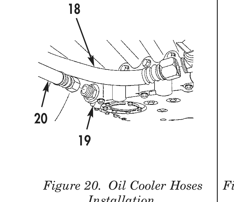
37. Connect two transmission oil cooler hoses (18) and (20) to transmission (19).
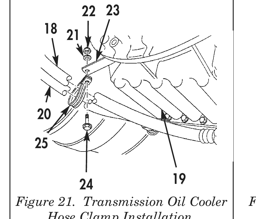
38. Install transmission oil cooler hoses (18) and (20) on transmission oil cooler base mounting bracket (23) with transmission oil cooler hose clamp (25), washer (21), screw (24), and nut (22).
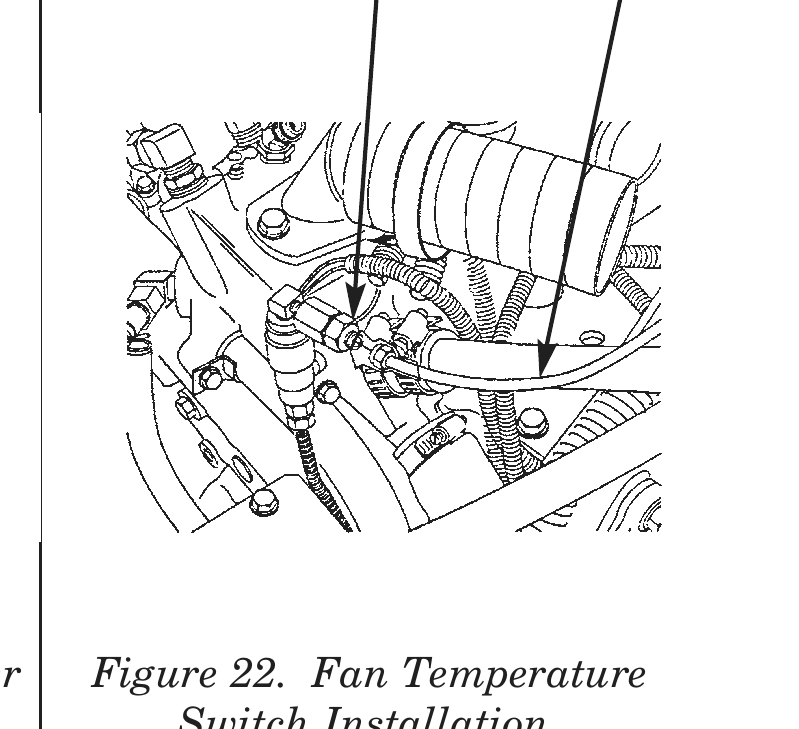
39. Connect air line (27) to fan temperature switch (26).
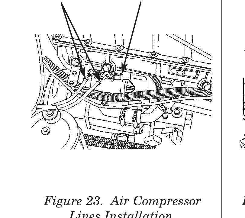
40. Connect two air lines (28) to air compressor (29).
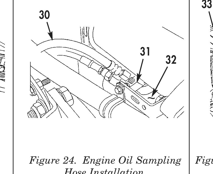
41. Connect oil sample hose (30) to elbow fitting (31) to oil filter housing (32).
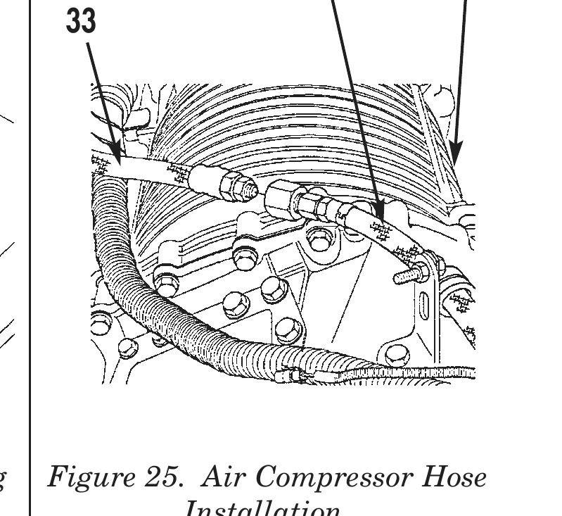
42. Connect air compressor hose (33) on top of transmission (22) to air compression hose (34).
26 27 22 23 18 21
24 19
Figure 20. Oil Cooler Hoses        Figure 21. Transmission Oil Cooler       Figure 22. Fan Temperature
        Installation.                   Hose Clamp Installation.                Switch Installation.
28 29 22
Figure 23. Air Compressor            Figure 24. Engine Oil Sampling        Figure 25. Air Compressor Hose
    Lines Installation.                     Hose Installation.                       Installation.
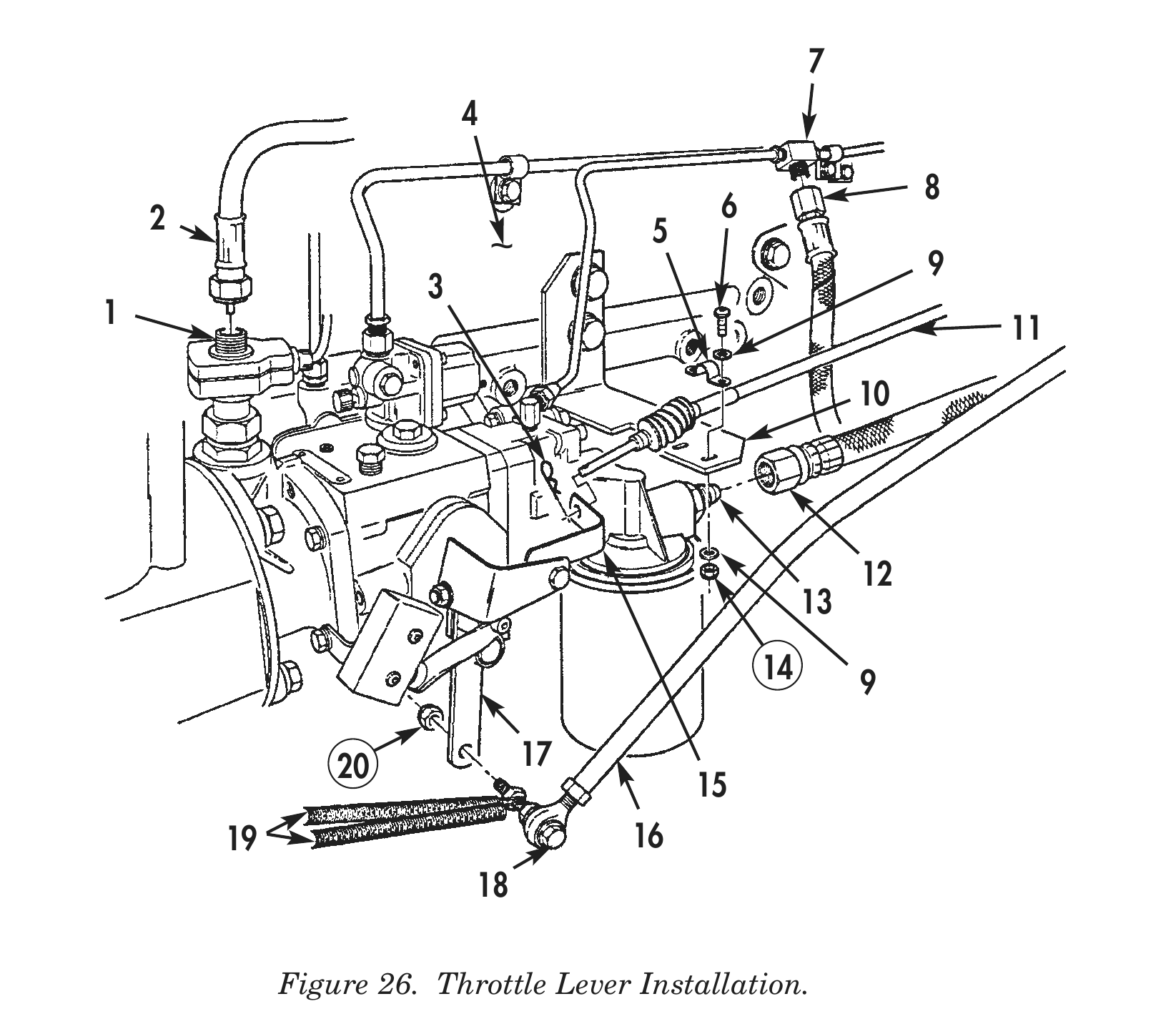
43. Install tachometer cable (2) on fuel pump tachometer drive (1).
44. Install accelerator rod (16) on lower throttle lever (17) with accelerator rod screw (18), new locknut (20), and two accelerator return springs (19).
45. Align locating mark on transmission modulator cable clamp (5) to locating mark on mounting bracket (10).
46. Install transmission modulator cable (11) on mounting bracket (10) with transmission modulator cable clamp (5), two screws (6), four washers (9), and two new locknuts (14).
47. Install transmission modulator cable (11) on throttle lever (15) with retaining pin (3).
48. Install fuel supply line (12) on fuel filter fitting (13).
49. Install fuel return line (8) to fuel return line T-fitting (7) on engine (4).
50. Install power steering hose (21) on elbow (25) of power steering reservoir (23).
51. Install two power steering hoses (21) and clamps (22) on power steering reservoir (23) and power steering pump (26). Tighten clamps (22).
52. Install drain plug (24) in power steering reservoir (23).
53. Install cooling fan (30) on cooling fan clutch studs (31) with six new cooling fan lockwashers (28), washers (29), and nuts (27).
2 6 ~ 9 1 11
14 9
20 17 19 16
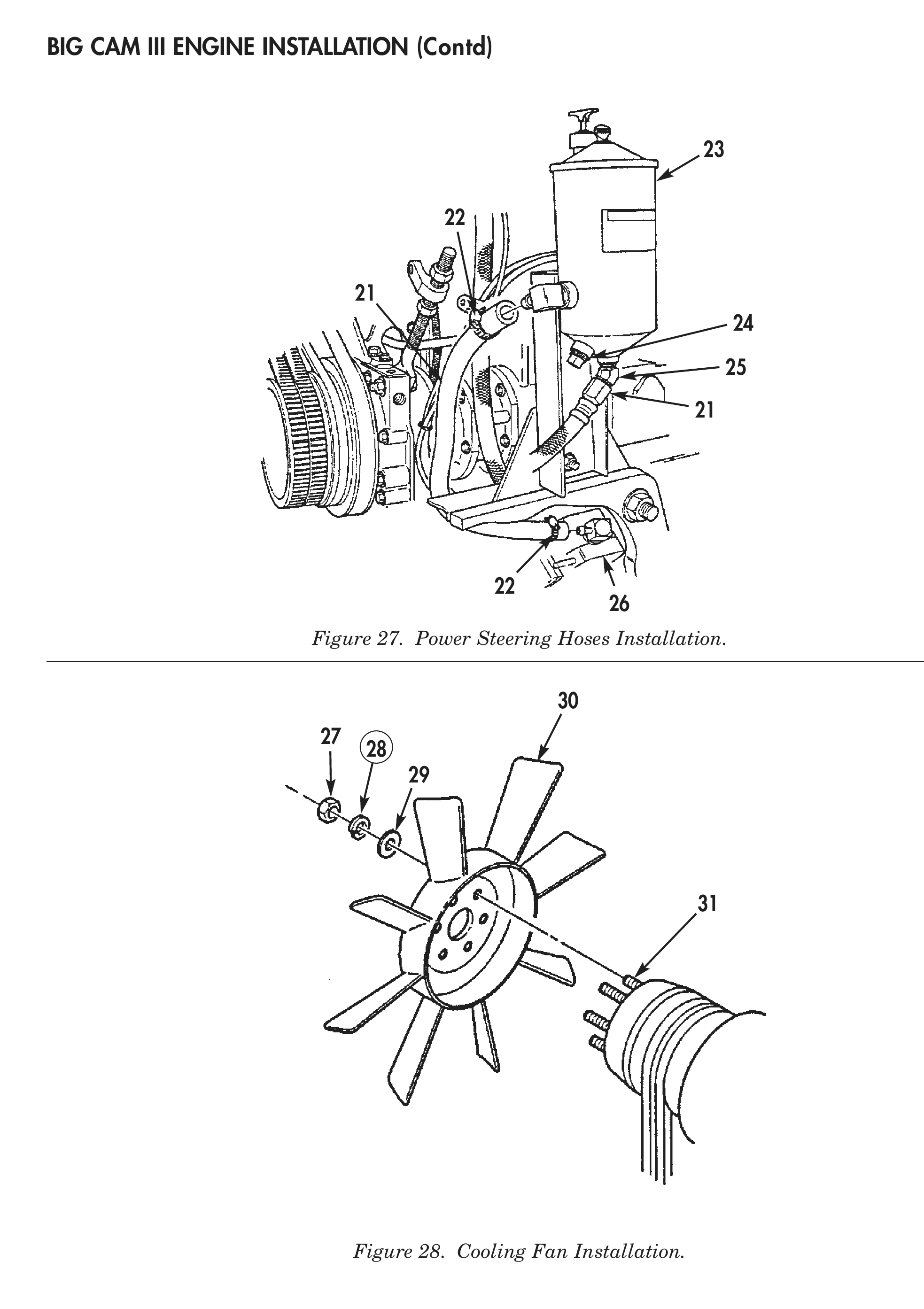
Figure 27. Power Steering Hoses Installation.
Figure 28. Cooling Fan Installation.
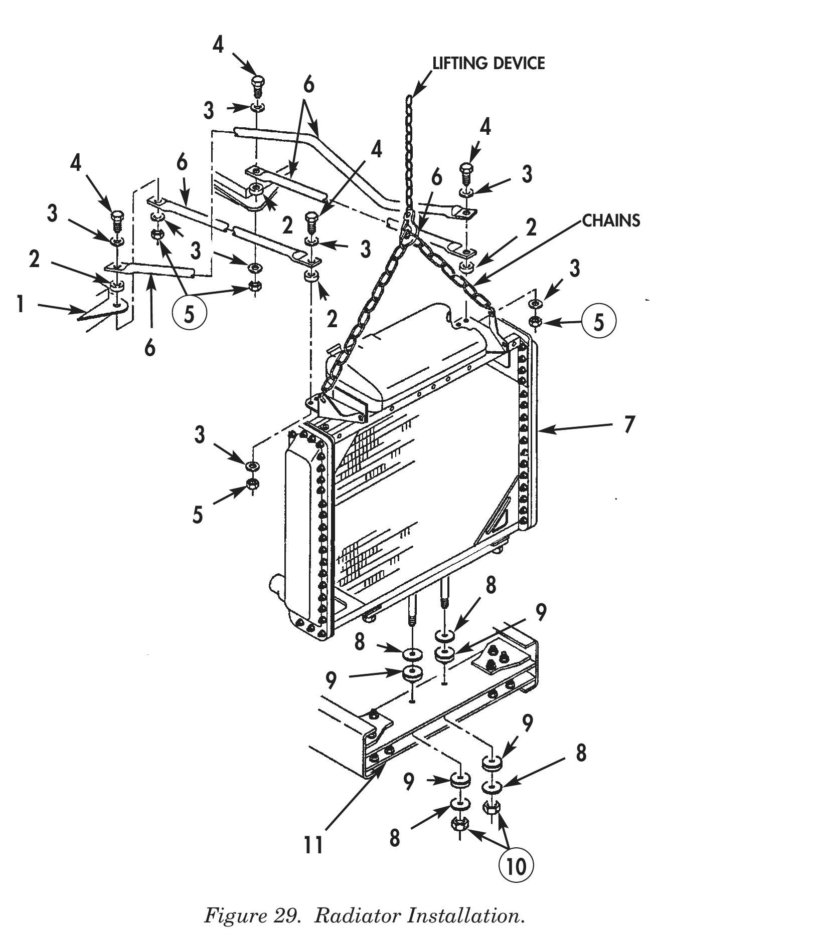
54. Install two isolators (9) and washers (8) on top of front crossmember (11).
55. Install chains and lifting device on radiator (7).
56. Using lifting device and chains, install radiator (7) on front crossmember (11).
57. Secure radiator to front of crossmember (11) with two radiator crossmember mount isolators (9), washers (8), and new locknuts (10).
58. Install three radiator support rods (6) on radiator (7) and firewall brackets (1) with four radiator support rod screws (4), eight washers (3), four spacers (2), and new locknuts (5).
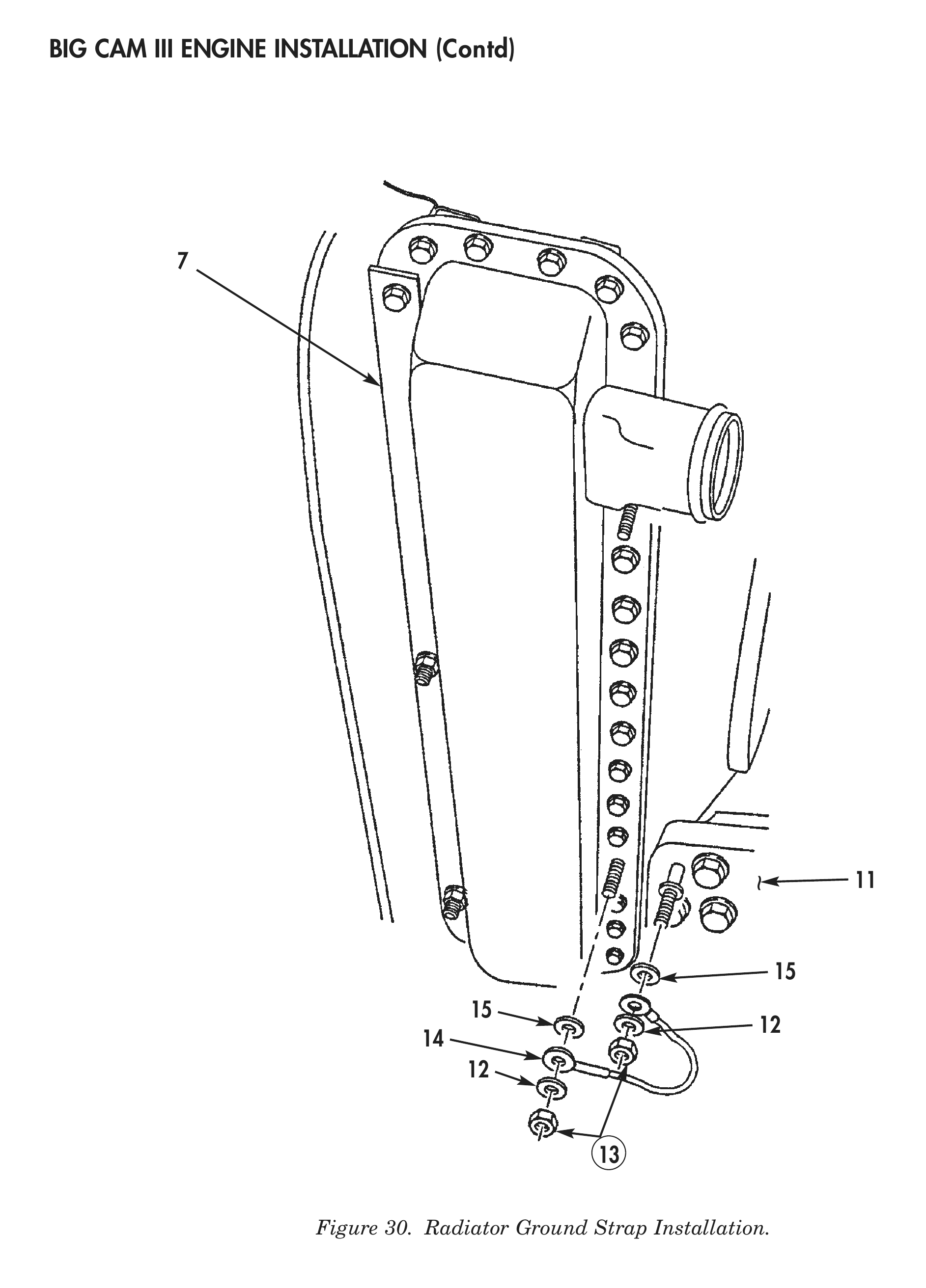
59. Install ground strap (14) on radiator (7) and frame front crossmember (11) with two ground strap isolators (15), washers (12), and new locknuts (13).
60. Remove chains and lifting device from radiator (7).
LIFTING DEVICE
4 6 6 3
3 CHAINS
2 2
    2                   3                       3
                                                                                   3
1                   5                       2                                           5
3 7
11 8
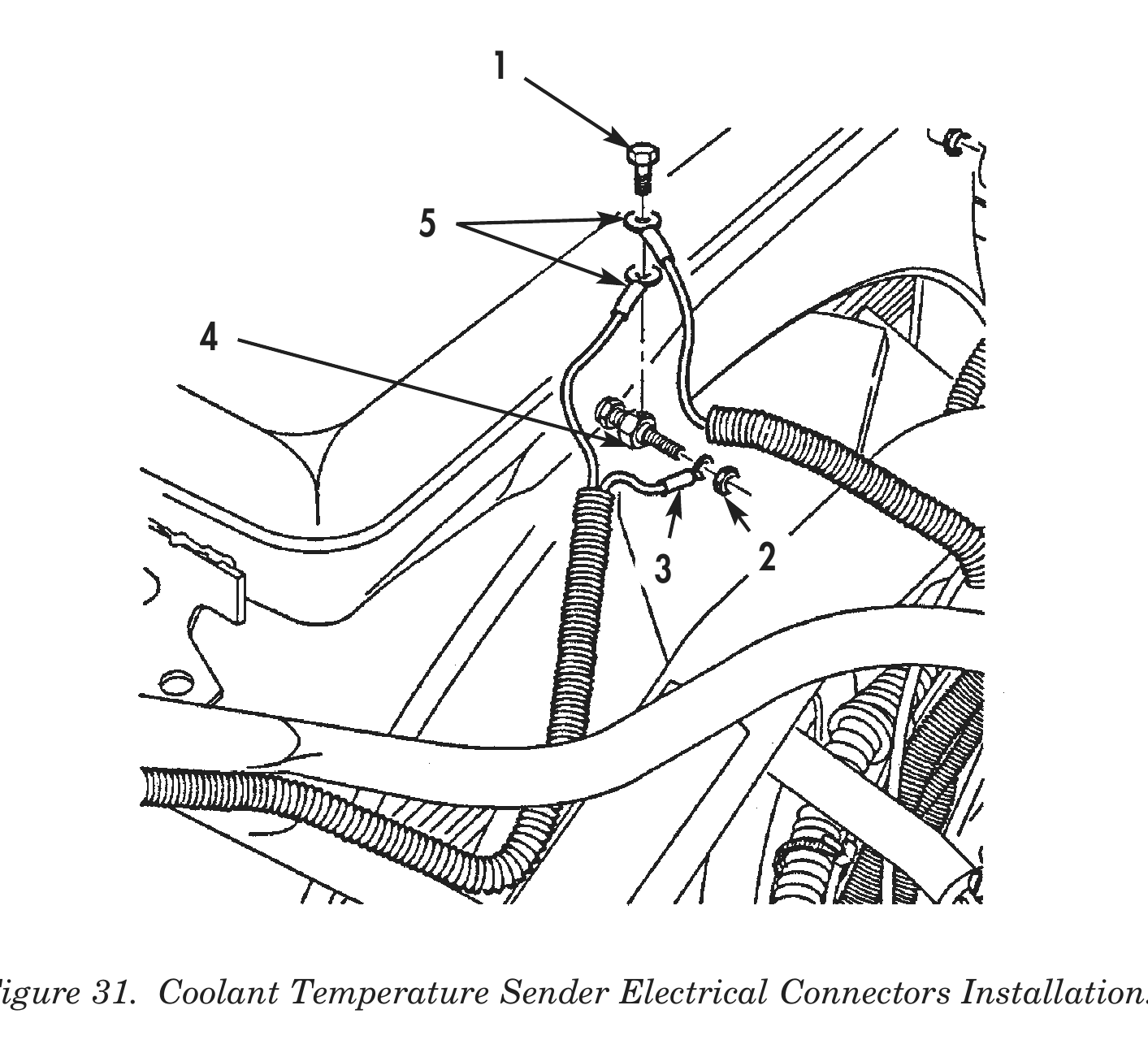
61. Install coolant temperature sender electrical connectors (5) on coolant temperature sender terminal (4) with coolant temperature sender terminal screw (1).
62. Install coolant temperature sender electrical connector (3) on coolant temperature sender terminal (4) with coolant temperature sender terminal nut (2).
63. Install A/C condensor (9) with A/C condensor lines (10) attached, on two support brackets (8) on front of radiator (15) with four new A/C condensor locknuts (7).
64. Install A/C condensor lines (10) on radiator support brackets (14) with three A/C condensor lines clamps (13), screws (6), washers (12), and new locknuts (11).
3 2
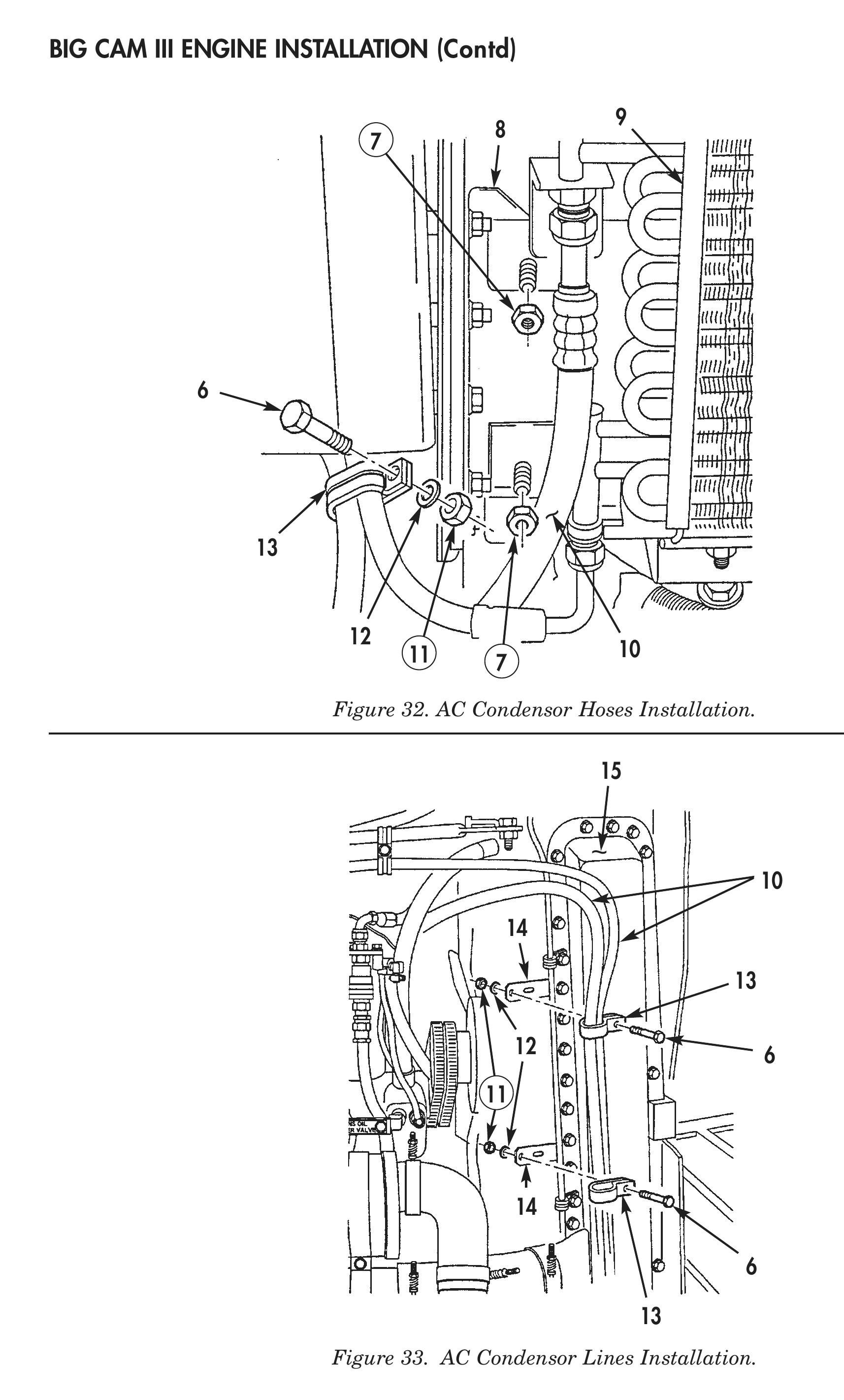
Figure 32. AC Condensor Hoses Installation.
Figure 33. AC Condensor Lines Installation.
65. Install A/C compressor (5) on mounting bracket (27) with two A/C compressor mounting bracket bolts (26), washers (24), and new locknuts (23).
66. Install A/C compressor adjusting rod (15) on front cover (16) with A/C compressor adjusting rod bolt (18), two washers (13), and new locknut (12).
67. Install A/C drive belt (19) on A/C clutch pulley (25) and accessory drive pulley (17).
68. Tighten two jam nuts (11) on A/C compressor adjusting rod (15) to obtain 0.50 in. (12.7 mm) A/C drive belt (19) deflection.
69. Install A/C compressor hose (4), clamp (1), screw (2), washer (22), and new locknut (21) on top of engine (20).
70. Install A/C compressor lines (3), two clamps (8) and (14), washers (10), and screws (9) on A/C compressor (5).
71. Connect A/C compressor clutch electrical connector (7) to engine wiring harness (6).
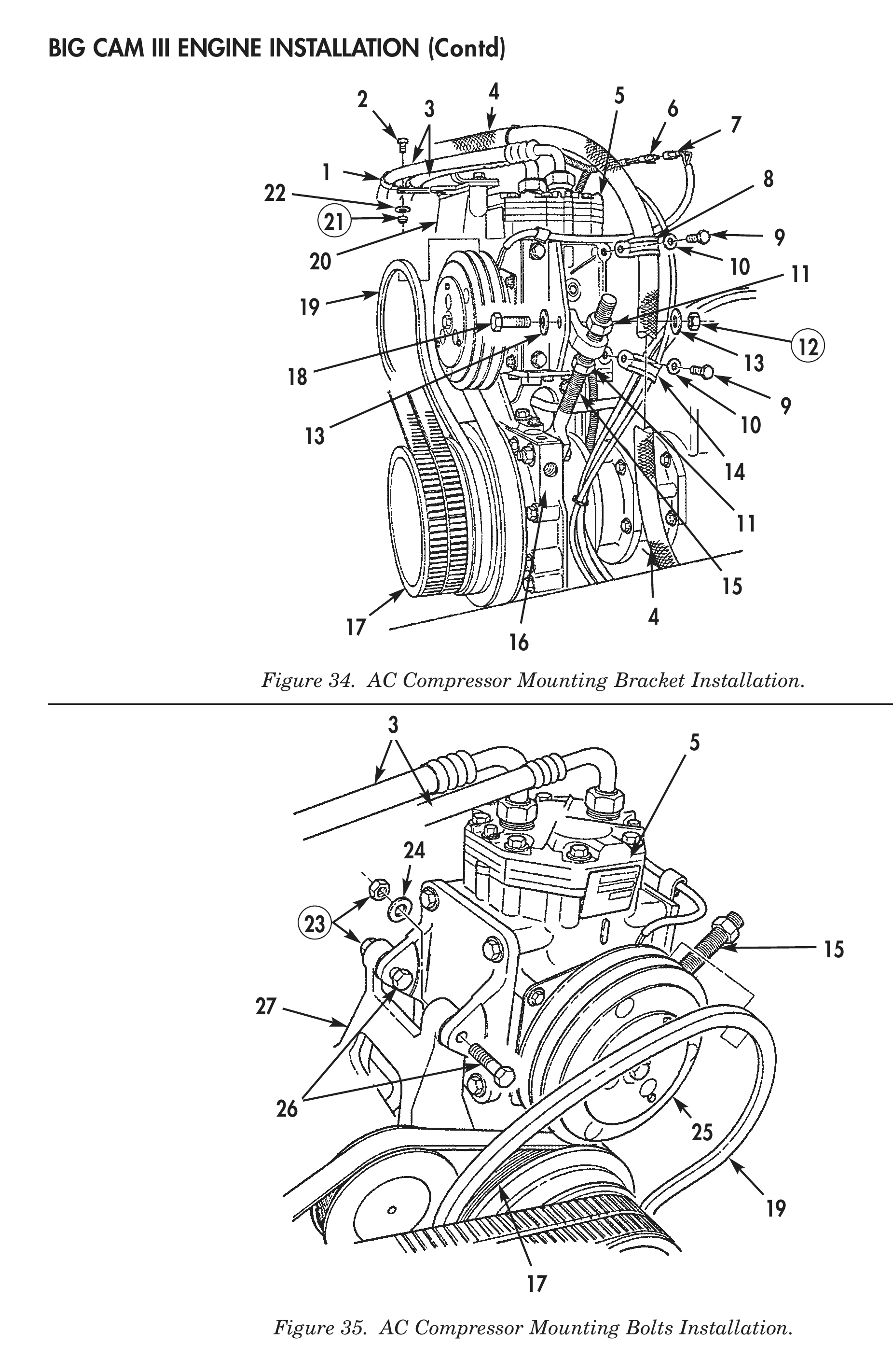
Figure 34. AC Compressor Mounting Bracket Installation.
Figure 35. AC Compressor Mounting Bolts Installation.
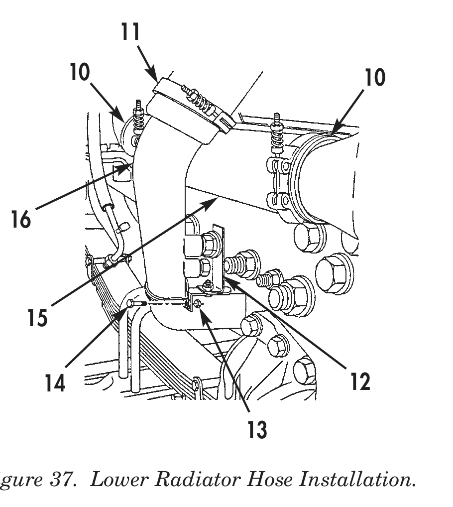
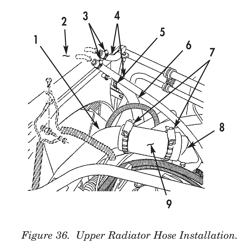
72. Install upper radiator hose (9) and two upper radiator hose clamps (7) on thermostat housing elbow (8) and radiator inlet tube (1). Tighten upper radiator hose clamps (7).
73. Install cooling outlet tube (16) and three clamps (11) on water pump (17). Tighten clamps (11).
74. Secure cooling tube outlet on support bracket (12) with cooling tube outlet screw (14) and nut (13).
75. Install lower radiator hose (15) and two lower radiator hose clamps (10) on radiator (2). Tighten clamps (10).
76. Install bypass hose (6) and clamp (5) on radiator (2). Tighten clamp (5).
77. Install two vent hoses (4) and clamps (3) on radiator (2). Tighten clamps (3).
78. Install heater hose (23) and clamp (22) on heater hose tube adapter (21). Tighten clamp (22).
79. Install heater hose (18) and clamp (19) on heater hose tube (20). Tighten clamp (19).
80. Install exhaust S-pipe (28) and clamp (24) on exhaust pipe (30) with two exhaust pipe screws (25) and nuts (29).
81. Install exhaust S-pipe (28) and clamp (26) on turbocharger outlet flange (27). Tighten clamp (26).
    3      4                                                           11
2
                      5                                           10                    10
1 6 ~ 7
14 12
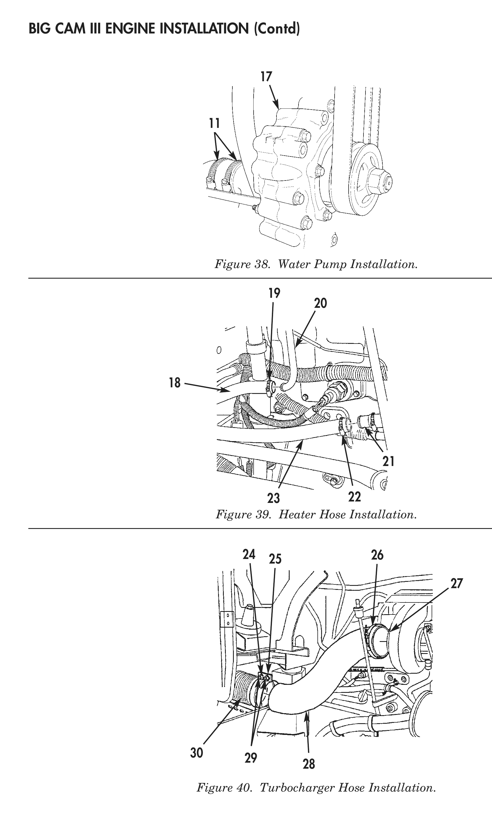
Figure 38. Water Pump Installation.
Figure 39. Heater Hose Installation.
Figure 40. Turbocharger Hose Installation.
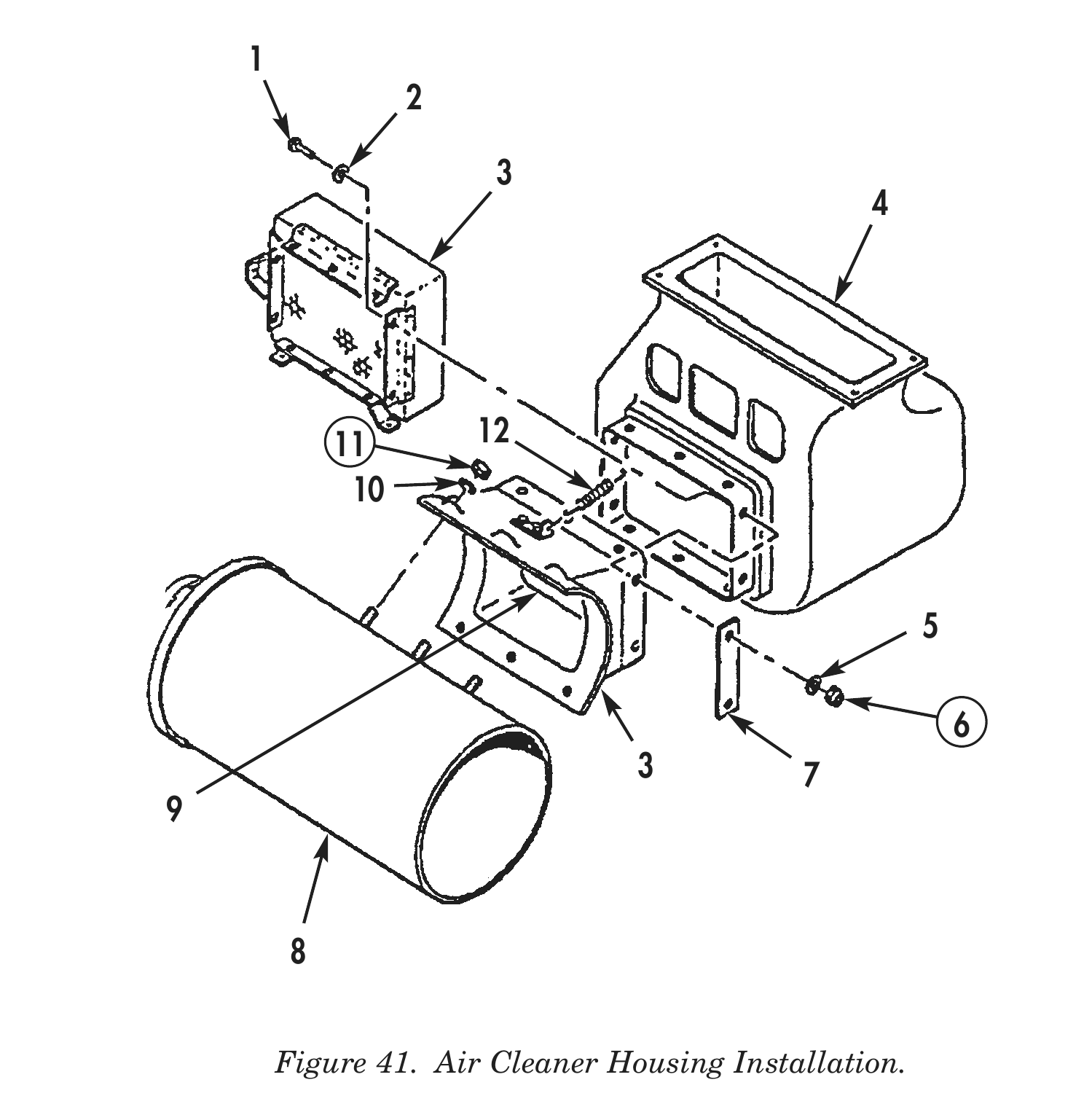
82. Install adapter duct (3) on air cleaner box (4) with four reinforcement plates (7), ten adapter duct screws (1), washers (5) and (2), and new locknuts (6).
83. Connect air duct door spring (12) on air duct door (9) and firewall (4).
84. Install air cleaner housing (8) on adapter duct (3) with six air cleaner housing washers (10) and new locknuts (11).
85. Install indicator tube (19) and elbow (18) on air cleaner housing (8).
86. Install air vent hose (17), two air vent hose clamps (16) on air duct support bracket (20) with four air cleaner housing bracket screws (22), washers (23), and new locknuts (24). Tighten clamps (16).
87. Install air vent tube (13) on air duct support bracket (20) with vent tube screw (14), washer (15), and locknut (21).
88. Install air cleaner duct assembly (29) and three clamps (28) on turbocharger outlet (30), outlet elbow (27), and air cleaner housing (8). Tighten clamps (28).
89. Install outlet elbow (27) on air chamber (31).
90. Install new air cleaner element (26) and three clamps (25) on air cleaner housing (8). Tighten clamps (25).
11 12
3 7
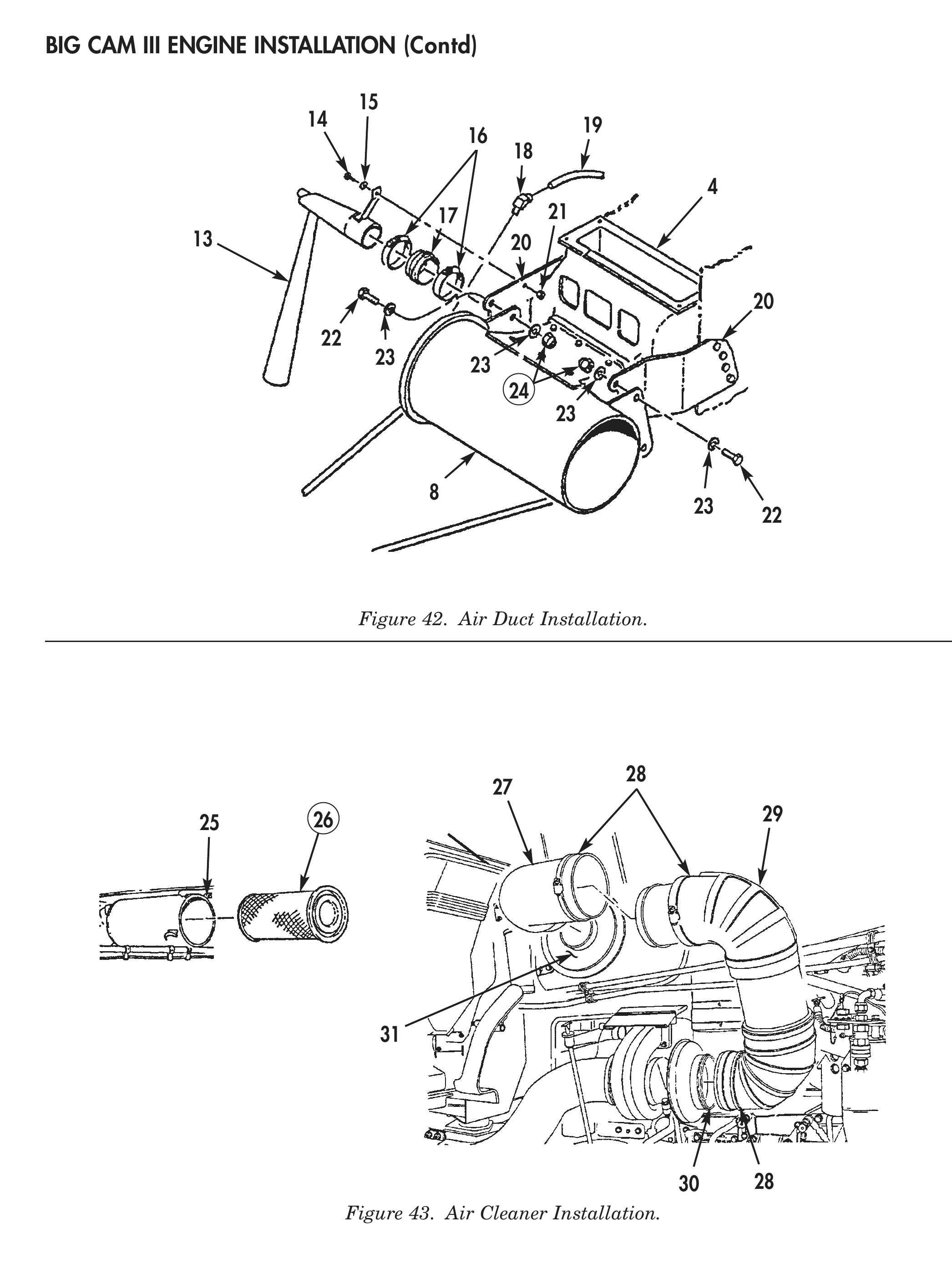
Figure 42. Air Duct Installation.
Figure 43. Air Cleaner Installation.
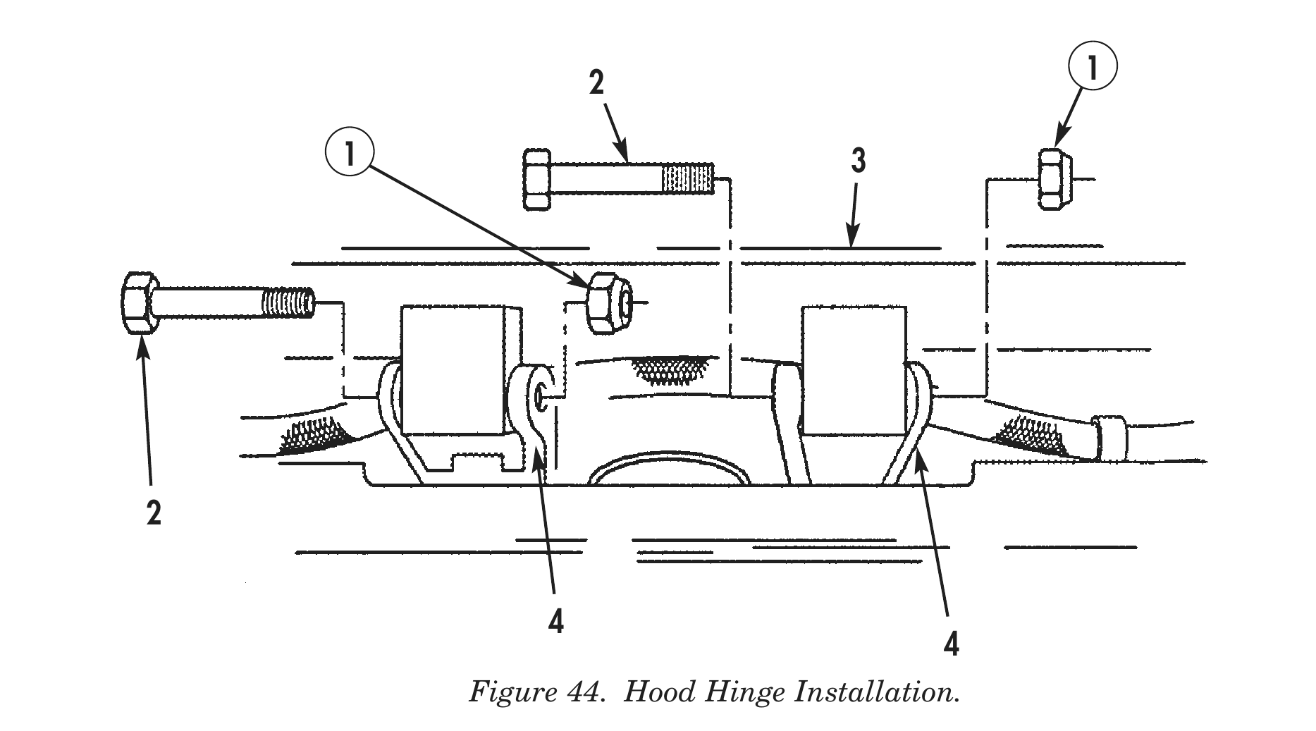
91. Install hood (3) on hood hinges (4) with two hood hinge bolts (2) and new locknuts (1).
92. Support hood (3) and install two tilt assist cables (5) connected to chain links (6) on chain links nuts (7).
93. Install lighting harness (13) on hood (3) with four lighting harness clamps (8), washers (9), screws (10), and new plastic tie (12).
94. Connect four electrical connectors (11) to lighting harness (13).
2 1
1 3
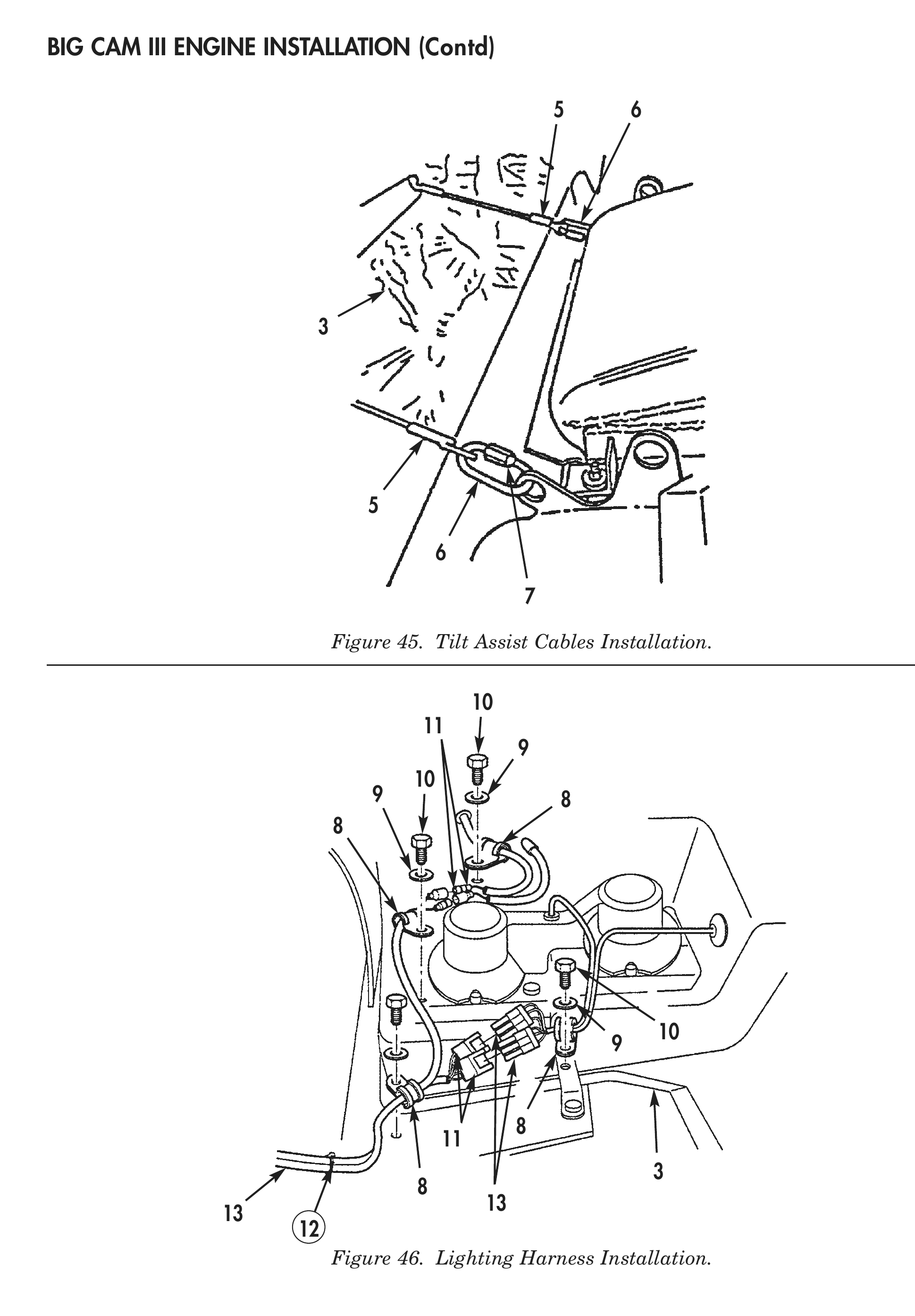
Figure 45. Tilt Assist Cables Installation.
Figure 46. Lighting Harness Installation.
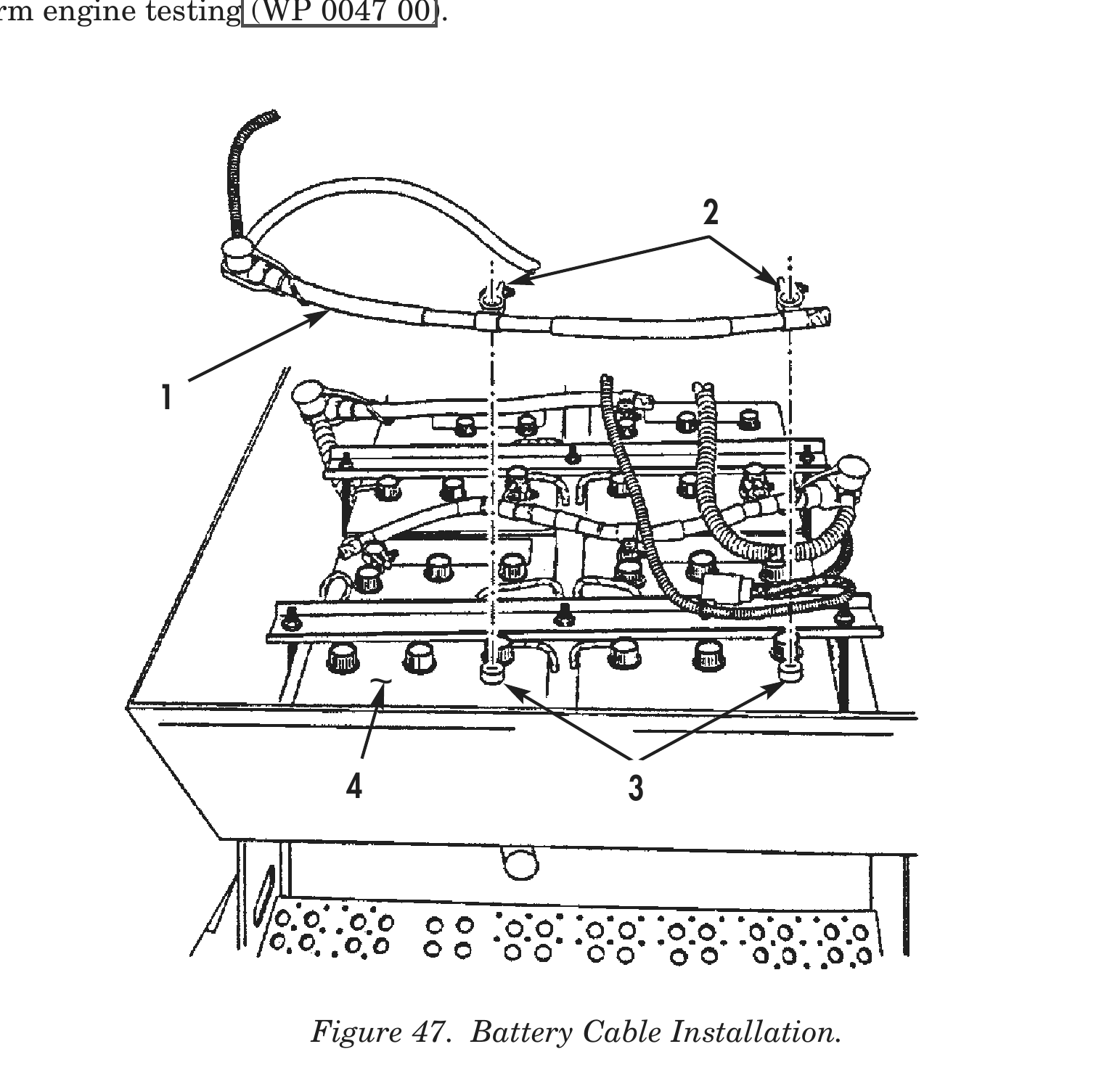
95. Fill cooling system with coolant to specified level (TM 9-2320-283-10).
96. Fill transmission with transmission oil to specified level (TM 9-2320-283-10).
97. Fill engine crankcase with engine oil to specified level (TM 9-2320-283-10).
98. Fill steering system with steering fluid to specified level (TM 9-2320-283-10).
99. Install negative battery cable (1) on battery (4) and connect two negative battery cable clamps (2) on two negative battery cable post (3). 100. Install brush guard and spotter mirrors (TM 9-2320-283-20). 101. Install bumper and towing eyes (TM 9-2320-283-20). 102. Install transmission oil cooler lines (TM 9-2320-283-20). 103. Close air reservoir draincocks (TM 9-2320-283-20). 104. Install upper radiator fan shroud (TM 9-2320-283-20). 105. Install fenders (TM 9-2320-283-20). 106. Install grill shell (TM 9-2320-283-20). 107. Install horn wire (TM 9-2320-283-20).
108. Perform engine testing (WP 0047 00).
4 3
END OF WORK PACKAGE