FUEL PUMP TESTING AND CALIBRATION
TM 9-2815-225-34&P · Work Package 0044 00
PREADJUSTMENT CHECKS, IDLE SPEED ADJUSTMENT, HIGH-SPEED ADJUSTMENT, CHECKING AND ADJUSTING FUEL RAIL, CHECKING AND ADJUSTING ENGINE FUEL, CHECKING AND ADJUSTING THROTTLE LEAKAGE, CHECKING FUEL FILTER RESTRICTION,
FUEL PUMP SEAL INSTALLATION, THROTTLE SHAFT COVER PLATE INSTALLATION
INITIAL SETUP
Tools and Special Tools                                Materials/Parts
 General mechanic’s tool kit: automotive               Snapring (Item 1, Table 27, WP 0062 00)
    (Item 1, WP 0061 00)                               Gasket (Item 2, Table 27, WP 0062 00)
 Maintenance and repair shop equipment,                Throttle shaft cover plate
    automotive (Item 2, WP 0061 00)                      (Item 3, Table 27, WP 0062 00)
 Automotive maintenance and repair
    supplemental set no. 2 (Item 3, WP 0061 00)
 Fuel pump idle adjusting tool
    (Item 60, WP 0061 00)
 Throttle shaft ball installing tool
    (Item 61, WP 0061 00)
PREADJUSTMENT CHECKS
IDLE SPEED ADJUSTMENT
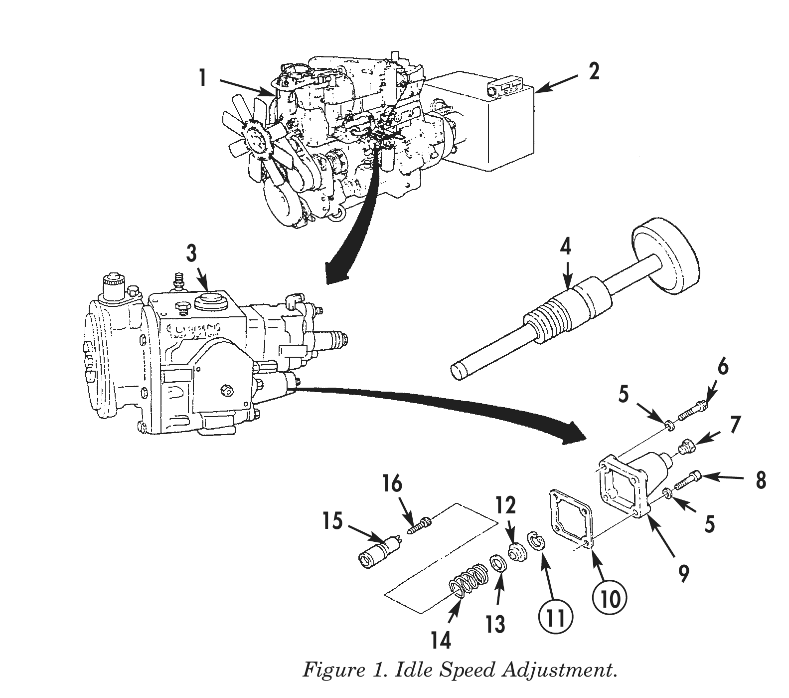
1. Remove plug (7) from spring pack cover (9) and start engine (1) on dynamometer (2).
2. Turn idle adjusting screw (16) in to increase engine rpm, out to decrease rpm.
3. Using idle adjusting tool (4), set idle to 600 +/- 2 rpm.
4. Install plug (7) on spring pack cover (9).
HIGH-SPEED ADJUSTMENT
1. Remove spring pack cover (9), three captive washer screws (6), screw (8), and four washers (5) from fuel pump (3).
2. Remove fuel pump gasket (10) from fuel pump (3). Discard gasket (10).
3. Remove snapring (11) from fuel pump (3). Discard snapring (11).
4. Remove spring retainer (12) from fuel pump (3).
5. Add or remove shims (13) behind spring (14). High-speed adjustment should be 2130 to 2150 rpm.
6. Install spring retainer (12) and new snapring (11) on guide (15).
7. Install spring pack cover (9) and new gasket (10) on fuel pump (3) with three captive washer screws (6), screw (8), and four washers (5). Tighten screws (6) and (8) 9–11 lb-ft (12–15 N•m).
8. Operate engine (1) to purge air from fuel system and bring up to operating temperature.
9. Bring engine (1) to full throttle and hold. Note maximum rpm. Speed should be 10–12 percent greater than governor speed cutoff point.
1 2
3 4
16 8 15 5
13 11 Figure 1. Idle Speed Adjustment.
CHECKING AND ADJUSTING FUEL RAIL
1. Check governor speed cutoff and adjust if necessary.
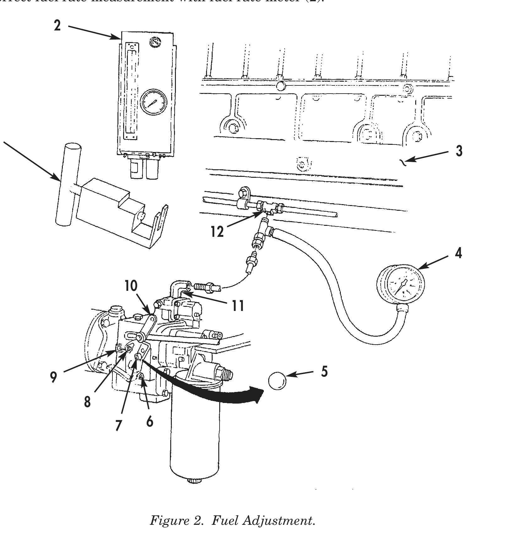
2. Install fuel rail pressure gauge (4) between fuel supply elbow (11) on fuel pump assembly (10) and female union tee (12).
3. Bring engine (3) to full throttle load until rpm falls to rated speed.
4. Note fuel rail pressure gauge (4) reading. If pressure is above or below 83 psi, perform steps 5–8.
5. Turn threaded stud (9) out to obtain maximum throttle travel and secure with jamnut (8).
6. Remove throttle shaft ball (5) from throttle shaft (6).
7. Turn fuel adjusting screw (7) in throttle shaft (6) in to increase or out to decrease pressure while watching fuel rail pressure gauge (4).
8. Using throttle shaft ball installing tool (1), install throttle shaft ball (5) into end of throttle shaft (6).
CHECKING AND ADJUSTING ENGINE FUEL
1. Connect fuel pump (10) to fuel rate meter (2).
2. Bring engine (3) to full throttle and increase dynamometer load until engine rpm falls to rated speed.
3. Check governor speed cut-off while load is on engine (3).
4. Check fuel rail pressure gauge (4) at maximum speed.
5. Hold engine speed and load at maximum speed long enough for fuel rate meter (2) to stabilize.
6. Verify correct fuel rate measurement with fuel rate meter (2).
9 5
7 6
CHECKING AND ADJUSTING THROTTLE LEAKAGE
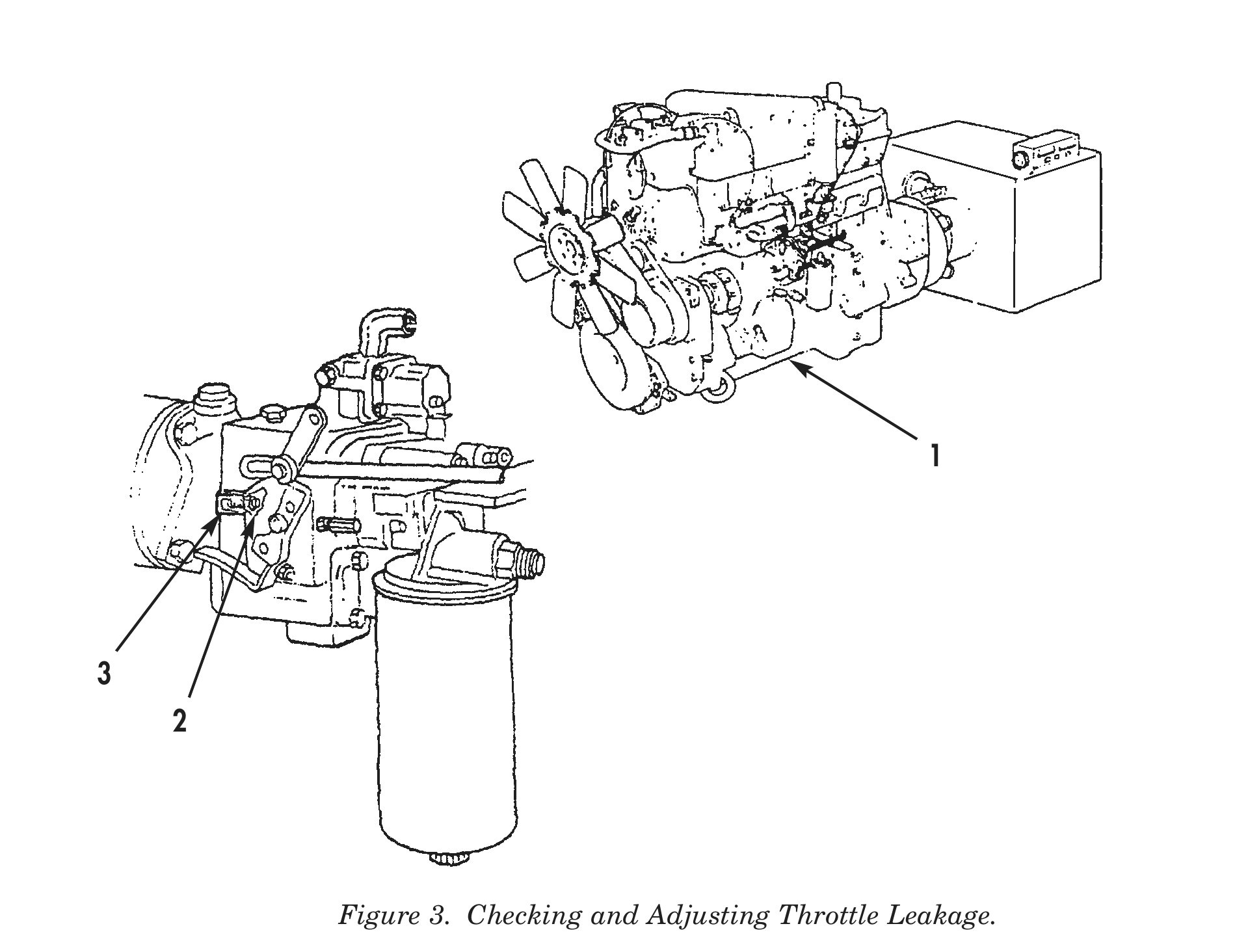
1. Bring engine (1) to full throttle and allow engine (1) to run at maximum no-load speed.
2. Release or move throttle quickly and start a suitable timer or stopwatch at the same time.
3. Stop timer when 1000 rpm is reached and check deceleration time. Repeat this check several times.
4. Increase leakage as engine (1) begins to stall (idle governor does catch engine after deceleration from high idle) by turning in threaded stud (3).
5. Recheck engine (1) deceleration until time is increased 1-2 seconds.
6. Lock threaded stud (3) with jamnut (2).
7. Recheck idle speed and readjust as necessary.
8. Bring engine to 1000 rpm.
CHECKING AND ADJUSTING THROTTLE LEAKAGE (Contd)
9. Check deceleration time when engine (1) is shut down.
10. Decrease leakage by turning threaded stud (3) out until engine (1) tends to stall after deceleration to high idle.
11. Turn in threaded stud (3) until deceleration is increased 1-2 seconds. Lock threaded stud (3) with jamnut (2).
12. Recheck idle speed and readjust as necessary.
13. Check fuel rail pressure, fuel rate, speed setting, smoke, coolant temperature, combustion smoothness, exhaust restriction, fuel quality, air intake restriction, engine oil level, and engine power reducing factors.
14. Check engine power by rechecking setting point of governor speed cutoff and readjust if necessary.
CHECKING FUEL FILTER RESTRICTION
1. Connect vacuum gauge (3) to fuel inlet (4) on fuel damper (5).
2. Bring engine (1) to full throttle and full load on dynamometer (2) and check vacuum gauge (3).
3. If restriction reads 8 in. (20.3 cm) of vacuum while engine is running at full throttle and full load, change fuel filter and check other sources of restriction.
4. Use sight glass to check for moving bubbles and possible gasket or other leaks. If air bubbles are still seen, check float valve in float tank used for test. Fuel pump may be pumping more fuel than float valve will allow to pass into the float tank.
FUEL PUMP SEAL INSTALLATION
1. Using lockwire and seal (8), insert lockwire through screw (12), plug (11), and threaded stud (14) on spring pack cover (13).
2. Twist lockwires together until connection is secure and lockwire is tight.
3. Bend twisted lockwire into seal and press on top half of seal.
4. Using lockwire and seal (8), insert lockwire through screw (10), drilled fillister head screw (9), and captive washer screw (7).
5. Twist lockwires together until connection is secure and lockwire is tight.
6. Bend twisted lockwire into seal and press on top half of seal.
THROTTLE SHAFT COVER PLATE INSTALLATION
1. Position new throttle shaft cover plate (6) on housing (16).
2. Drill two new holes on opposite sides of throttle shaft cover plate (6) 0.235 in. (5.969 mm) into pump housing (16).
3. Secure new throttle shaft cover plate (6) on housing (16) with two drive screws (15).
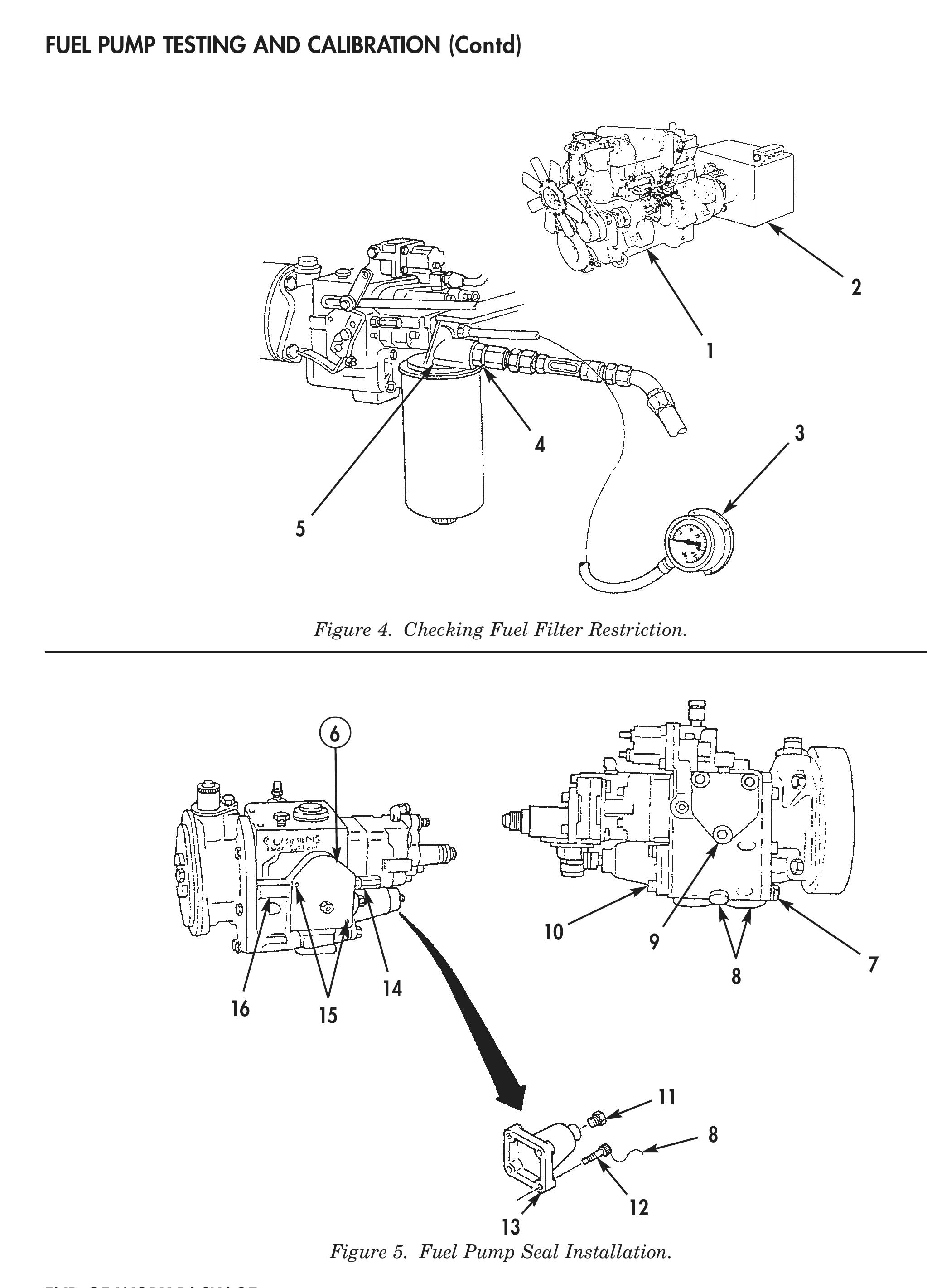
Figure 4. Checking Fuel Filter Restriction.
Figure 5. Fuel Pump Seal Installation.