PISTONS, CONNECTING RODS, AND BEARINGS
TM 9-2815-225-34&P · Work Package 0018 00
DISASSEMBLY, CLEANING AND INSPECTION, ASSEMBLY
INITIAL SETUP
Tools and Special Tools                               Materials/Parts (Contd)
 General mechanic’s tool kit: automotive               Six intermediate compression rings
    (Item 1, WP 0061 00)                                 (Item 5, Table 3, WP 0062 00)
 Maintenance and repair shop equipment:                Six oil control rings
    automotive (Item 2, WP 0061 00)                      (Item 6, Table 3, WP 0062 00)
 Automotive maintenance and repair
    supplemental set no. 2 (Item 3, WP 0061 00)       Equipment Condition
 Connecting rod bushing driver                         Piston, connecting rod, and bearing removed
    (Item 25, WP 0061 00)                                from engine (WP 0012 00).
 Piston ring groove gauge
    (Item 27, WP 0061 00)
 Piston ring expander (Item 28, WP 0061 00)
 Connecting rod checking fixture
    (Item 26, WP 0061 00)
 0.125 in. (3.175 mm) diameter rod
    (Item 41, WP 0061 00)
 Press
 Oven

Materials/Parts
 Crocus cloth (Item 4, WP 0060 00)
 Rubber gloves (Item 32, WP 0060 00)
 Lubricating oil (Item 19, WP 0060 00)
 Six bushings (Item 1, Table 3, WP 0062 00)
 Twelve connecting rod bearings
   (Item 2, Table 3, WP 0062 00)
 Six first compression rings
   (Item 3, Table 3, WP 0062 00)
 Six second compression rings
   (Item 4, Table 3, WP 0062 00)
DISASSEMBLY
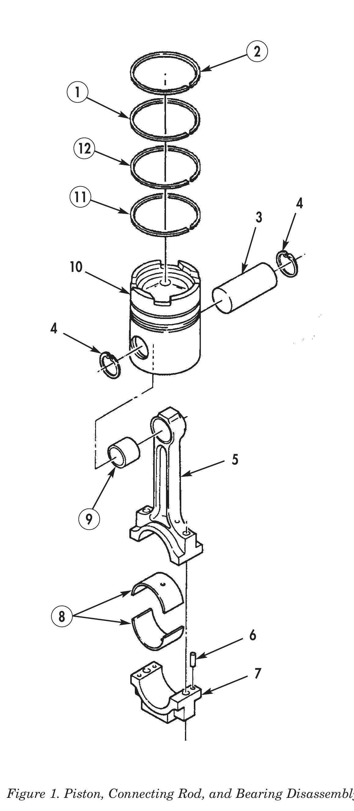
1. Remove first compression ring (2), second compression ring (1), intermediate compression ring (12), and oil control ring (11) from piston (10). Discard piston rings (2), (1), (12), and (11).
2. Remove connecting rod bearings (8) from connecting rod (5) and connecting rod cap (7) if not previously removed. Discard connecting rod bearings (8).
3. Remove two dowel pins (6) from connecting rod cap (7).
4. Remove two retaining rings (4) from piston (10).
5. Heat piston (10), piston pin (3), and connecting rod (5) to 210° F (98.9° C) for 10 minutes in boiling water or oven.
6. Remove piston pin (3) from piston (10) and connecting rod (5).
7. Remove piston (10) from connecting rod (5).
8. Using press and connecting rod bushing driver, remove bushing (9) from connecting rod (5). Discard bushing (9).
9. Repeat steps 1 through 8 for all remaining piston (10), connecting rod (5), and bearing (8) assemblies.
CLEANING AND INSPECTION
1. For general parts cleaning information, refer to CLEANING, WP 0051 00.
2. For general parts inspection information, refer to INSPECTION, WP 0051 00.
3. Inspect piston (1) for cracks, breaks, scores, galling, or scratches. Remove small scratches with crocus cloth.
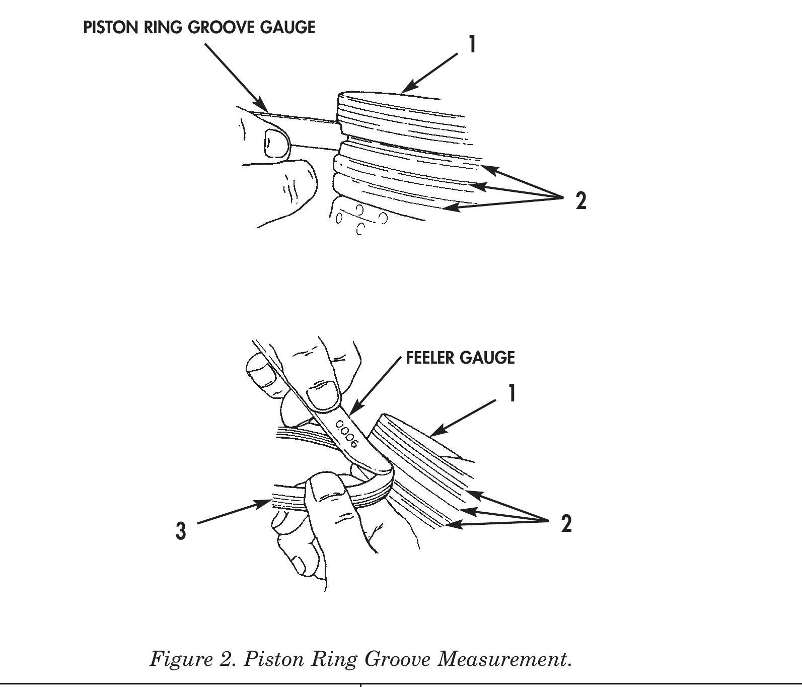
4. Inspect piston ring grooves (2) for cracks, breaks, missing sections, and galling.
5. Using piston ring groove gauge, measure piston ring groove (2). Discard piston (1) if piston ring groove gauge widest shoulder comes in contact with piston (1).
6. Position a new piston ring (3) in piston ring groove (2). Using a feeler gauge, check the clearance between piston ring (3) and piston ring groove (2). Replace piston (1) if clearance is more than 0.006 in. (0.15 mm).
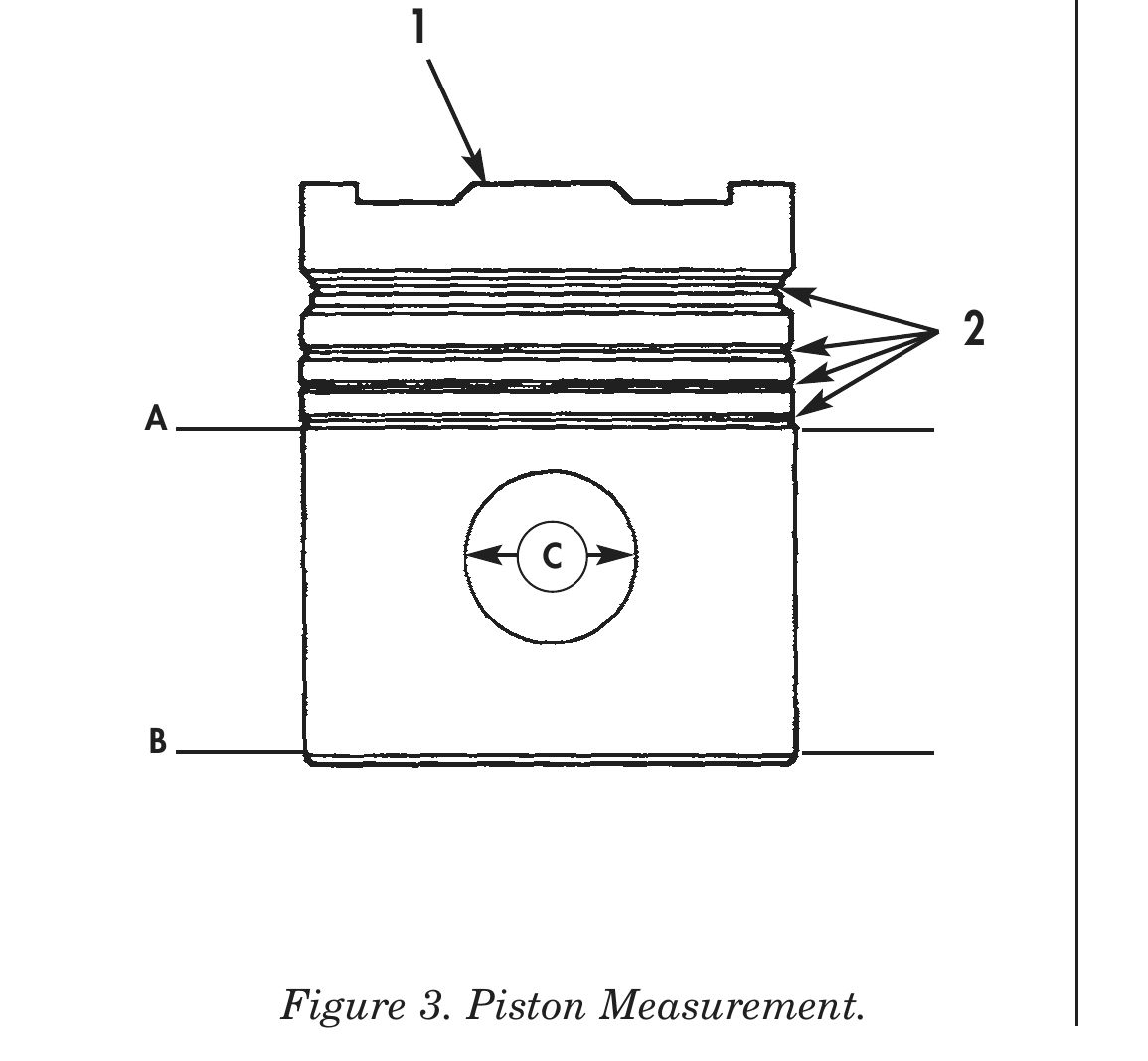
7. Using micrometer or equivalent, measure piston outside diameter at point A, 1.0 in. (25.4 mm) below piston ring groove (2). Piston outside diameter at point A should be 5.477–5.480 in. (13.912–13.919 cm). Replace piston (1) if worn beyond specifications.
8. Using micrometer or equivalent, measure piston skirt outside diameter at point B, 1.0 in. (25.4 mm) above bottom of piston (1). Piston outside diameter at point B should be 5.489–5.493 in. (13.942–13.952 cm). Replace piston (1) if worn beyond specifications.
9. Using inside micrometer, measure piston pin bore at point C. Piston pin bore should be 1.9985–1.9990 in. (5.076–5.078 cm). Replace piston (1) if piston pin bore is above 2.0000 in. (5.080 cm).
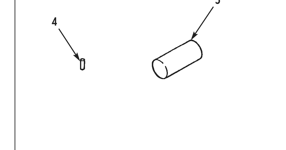
10. Using micrometer or equivalent, measure piston pin (5) outside diameter. Piston pin (5) should be 1.9988–1.9990 in. (5.0769–5.0775 cm). Replace piston pin (5) if outside diameter is out of round more than 0.001 in. (0.025 mm).
11. Inspect dowel pins (4) for cracks, chips, and bends.
12. Using micrometer, measure outside diameter of two dowel pins (4). Dowel pins (4) should be 0.220–0.250 in. (5.59–6.35 mm). Replace dowel pins (4) if not within specifications.
PISTON RING GROOVE GAUGE
FEELER GAUGE
3 2
2 4
A
C
B
CLEANING AND INSPECTION (Contd)
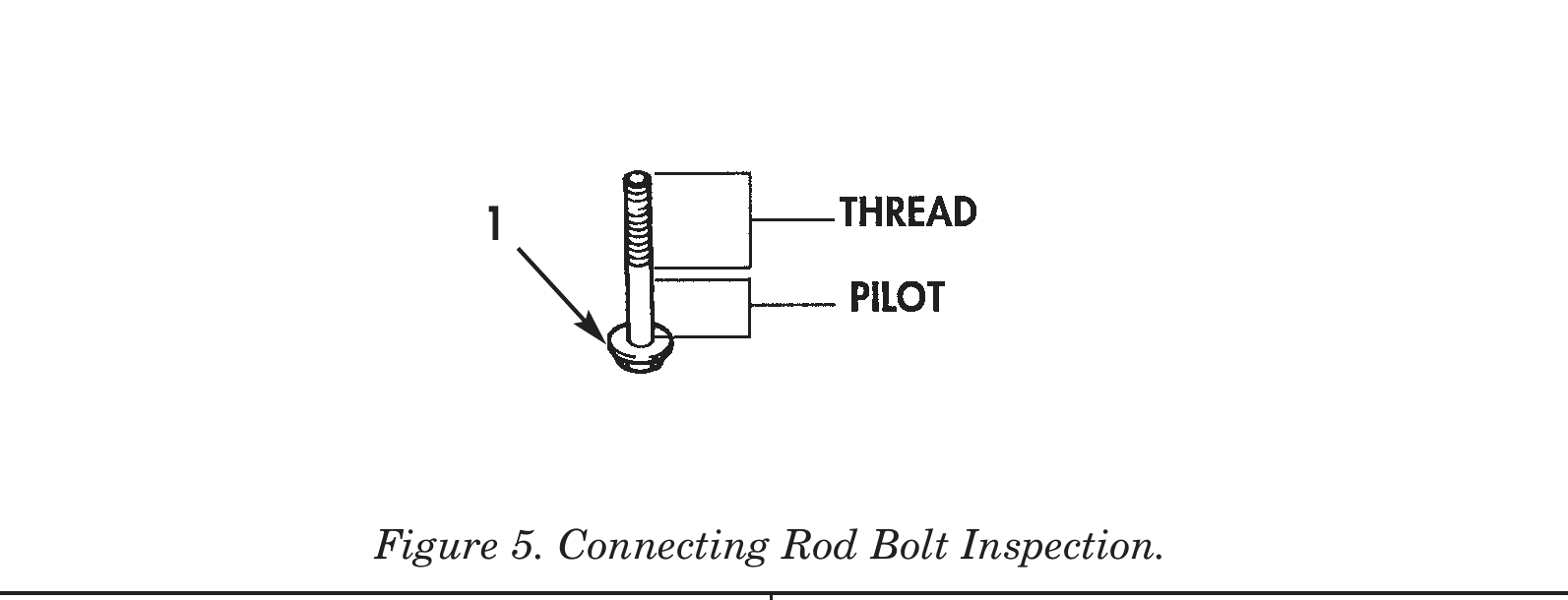
13. Inspect twelve connecting rod bolts (1) for bends, cracks, chipped or stripped teeth. Replace connecting rod bolts (1) if damaged.
14. Using a micrometer, inspect connecting rod bolt (1) pilot area outside diameter. Outside diameter of pilot area should be 0.541–0.545 in. (13.74–13.84 mm). Replace any connecting rod bolt (1) if outside diameter of pilot area exceeds 0.540 in. (13.72 mm).
15. Using a micrometer, inspect connecting rod bolt (1) threaded area outside diameter. Outside diameter of threaded area should be 0.6245–0.6250 in. (15.862–15.875 mm). Replace connecting rod bolt (1) if outside diameter of threaded area exceeds 0.6242 in. (15.855 mm).
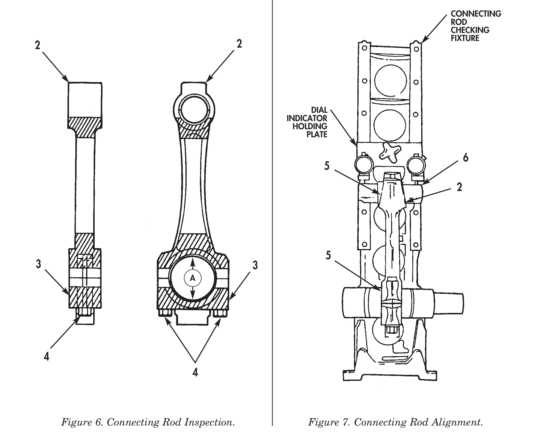
16. Inspect connecting rod (2) and connecting rod cap (3) for nicks, dents, scratches, and gouges. Replace connecting rod (2) and connecting rod cap (3) if any nicks, dents, scratches, or gouges are deeper than 0.03125 in. (0.7938 mm).
17. Install connecting rod cap (3) on connecting rod (2) with two connecting rod bolts (4). Tighten bolts (4) 140–150 lb-ft (190–203 N•m).
18. Using inside micrometer, measure inside diameter of connecting rod (2) at connecting rod cap (3) assembly at point A. Connecting rod inside diameter should be 3.3157–3.3167 in. (8.4219–8.4244 cm). Replace connecting rod (2) and connecting rod cap (3) if not within specifications.
19. Install connecting rod (2) on connecting rod checking fixture.
20. Using connecting rod checking fixture, check connecting rod (2) length. Replace connecting rod (2) if longer than calibration rod on connecting rod checking fixture, or if more than 0.002 in. (0.050 mm) shorter.
21. Using connecting rod checking fixture, check alignment of connecting rod bores (5). Take first measurement of connecting rod bores (5). Remove connecting rod (2) from connecting rod checking fixture. Rotate connecting rod (2) 180°, install on connecting rod checking fixture, and take second measurement. Replace connecting rod (2) if there is more than 0.010 in. (0.254 mm) difference in measurements.
22. Using feeler gauge, measure connecting rod (2) for twist between piston pin holding mandrel (6) and dial indicator holding plate. Replace connecting rod (2) if clearance between piston pin holding mandrel (6) and dial indicator holding plate is more than 0.020 in. (0.5078 mm).
CONNECTING
ROD
CHECKING
FIXTURE
2 2
DIAL
INDICATOR
HOLDING
PLATE
3 3 A
Figure 7. Connecting Rod Alignment.
ASSEMBLY
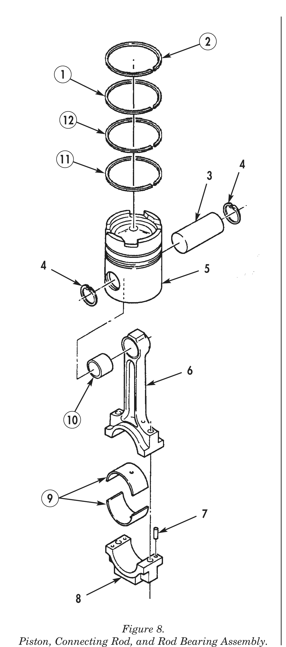
1. Align oil holes in new bushing (10) with oil holes in connecting rod (6). Using press and connecting rod bushing driver, install new bushing (10) in connecting rod (6). Ensure that 0.125 in. (3.175 mm) diameter rod can pass easily through oil holes.
2. Install one retaining ring (4) in piston (5).
3. Heat piston (5) to 210° F (98.9° C) for 15 minutes in water or oven.
4. Position connecting rod (6) in piston (5) and install connecting rod (6) to piston (5) with piston pin (3).
5. Install retaining ring (4) in piston (5).
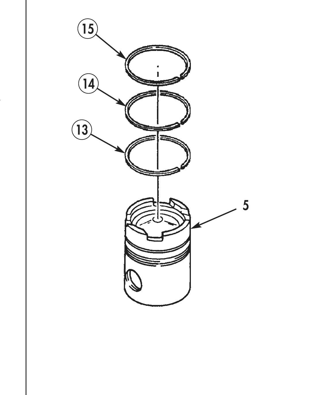
6. Using piston ring expander, install three new piston rings (13), (14), and (15) on piston (5) with word “top” facing up. Start with new oil control ring (13) on bottom, new second compression ring (14) in middle, and new first compression ring (15) on top.
7. Using piston ring expander, install four new piston rings (11), (12), (1), and (2) on piston (5) with word “top” facing up. Start with new oil control ring (11) on bottom, new intermediate compression ring (12) second from bottom, new second compression ring (1) in middle, and a new first compression ring (2) on top.
8. Install two dowel pins (7) in connecting rod cap (8).
9. Install new connecting rod bearings (9) in connecting rod (6) and connecting rod cap (8).
10. Repeat steps 1 through 9 for all remaining piston (5), connecting rod (8), and bearing (7) assemblies.
11. For piston, connecting rod, and bearing installation, refer to WP 0042 00.
11 4
4 5
Figure 8. Piston, Connecting Rod, and Rod Bearing Assembly.
Figure 9. Replacement Piston Ring Assembly.
END OF WORK PACKAGE