TURBOCHARGER
TM 9-2815-225-34&P · Work Package 0026 00
DISASSEMBLY, CLEANING AND INSPECTION, ASSEMBLY
INITIAL SETUP
Tools and Special Tools                                Equipment Condition
 General mechanic’s tool kit: automotive               Turbocharger removed from engine
    (Item 1, WP 0061 00)                                 (WP 0009 00).
 Maintenance and repair shop equipment:
    automotive (Item 2, WP 0061 00)
 Automotive maintenance and repair
    supplemental set no. 2 (Item 3, WP 0061 00)
 Press

Materials/Parts
 Crocus cloth (Item 4, WP 0060 00)
 Antiseize compound (Item 7, WP 0060 00)
 OE/HDO 30 lubricating oil
   (Item 20, WP 0060 00)
 Locknut (Item 3, Table 10, WP 0062 00)
 Sleeve (Item 1, Table 10, WP 0062 00)
 Ring seal (Item 2, Table 10, WP 0062 00)
 Bearing insert pad
   (Item 3, Table 10, WP 0062 00)
 Impeller locknut
   (Item 4, Table 10, WP 0062 00)
 Screw (Item 5, Table 10, WP 0062 00)
 Diffuser plate (Item 6, Table 10, WP 0062 00)
 O-ring (Item 7, Table 10, WP 0062 00)
 Bearing (Item 9, Table 10, WP 0062 00)
 Insulated packing
   (Item 10, Table 10, WP 0062 00)
 Two ring seals (Item 11, Table 10, WP 0062 00)
DISASSEMBLY
1. For removal of turbocharger, refer to WP 0010 00.
2. Scribe locating mark (2) on impeller housing (1), bearing housing (4), and turbine housing (3) before disassembly.
3. Remove two adapters (12) and (19) from bearing housing (4).
4. Remove two locknuts (8), screws (11), four washers (7) and (10), and V-band clamp (9) from impeller housing (1), bearing housing (4), and turbine housing (3). Discard locknuts (8) and screws (11).
5. Remove impeller housing (1) from bearing housing (4).
6. Remove turbine housing (3) from bearing housing (4).
7. Remove impeller locknut (6) from wheel and shaft assembly (23). Discard locknut (6).
8. Using press, remove wheel and shaft assembly (23) and turbocharger impeller (5) from bearing housing (4).
9. Remove heat shield (21) and insulated packing (20) from bearing housing (4). Discard insulated packing (20).
10. Remove diffuser plate (15), bearing insert pad (17), and bearing (18) from bearing housing (4). Discard bearing insert pad (17), bearing (18) and diffuser plate (15) which includes sleeve (13), ring seal (14) and O-ring (16).
11. Remove two ring seals (22) from wheel and shaft assembly (23). Discard ring seals (22).
CLEANING AND INSPECTION
1. For general parts cleaning information, refer to CLEANING, WP 0051 00.
2. For general parts inspection information, refer to INSPECTION, WP 0051 00.
3. Inspect impeller housing (1) and turbine housing (3) for cracks, chips, and scratches. Remove small scratches and chips from machined surfaces with crocus cloth.
4. Inspect diffuser plate (15) for cracks or damage at bearing insert pad (17), contact point.
5. Inspect heat shield (21) for cracks and chips.
6. Using a straightedge, inspect heat shield (21) for straightness. Discard heat shield (21) if warped.
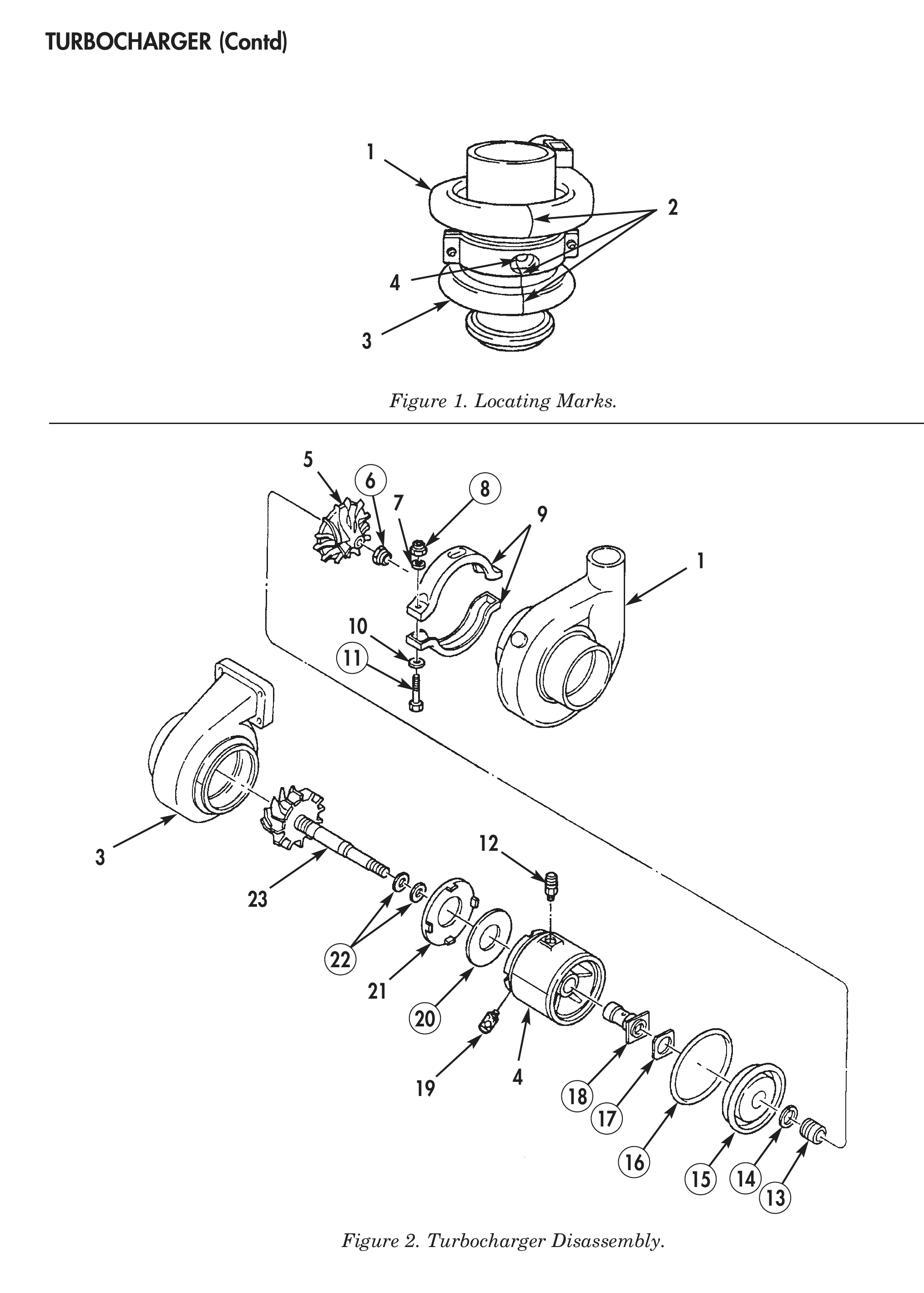
Figure 1. Locating Marks.
Figure 2. Turbocharger Disassembly.
CLEANING AND INSPECTION (Contd)
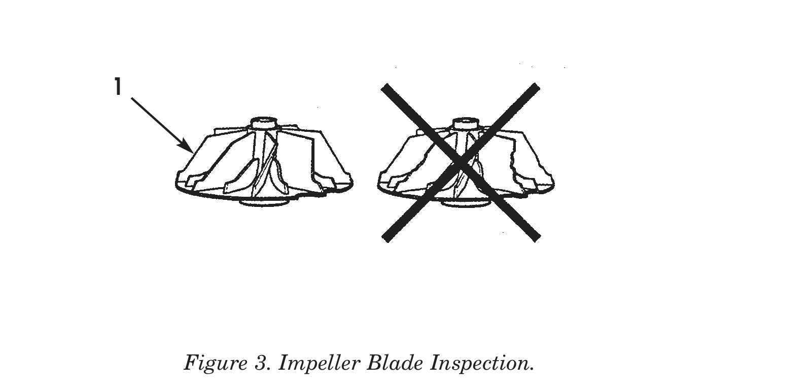
7. Inspect turbocharger impeller blades (1) for cracks and chips.
8. Inspect bearing housing (2) for cracks, chips, and scratches. Remove small scratches and chips from machined surfaces with crocus cloth.
9. Measure bearing housing (2) from compressor housing stop to turbine housing stop at four equal locations. Minimum length is 2.986 in. (7.584 cm). Replace bearing housing (2) if distorted.
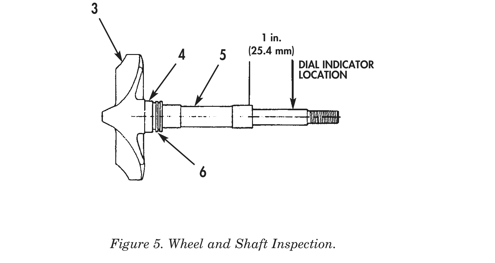
10. Inspect turbine blades (3) for cracks and chips.
11. Inspect wheel and shaft seal ring grooves (6) for small grooves, chips, or cracks. Remove small grooves with crocus cloth.
12. Inspect wheel and shaft weld area (4) for chips, scratches, or cracks. Replace wheel and shaft (5) if three or more cracks are found, or if cracks exceed 0.375 in. (9.525 mm) in length, have a minimum distance of 0.250 in. (6.35 mm), or exceed 0.0625 in. (1.587 mm) in length on welded area (4) circumference.
13. Using dial indicator, measure wheel and shaft (5) runout 1 in. (25.4 mm) from bearing surface of wheel and shaft (5). Wheel and shaft (5) maximum runout is 0.00005 in. (0.0127 mm). Discard wheel and shaft (5), if runout is exceeded.
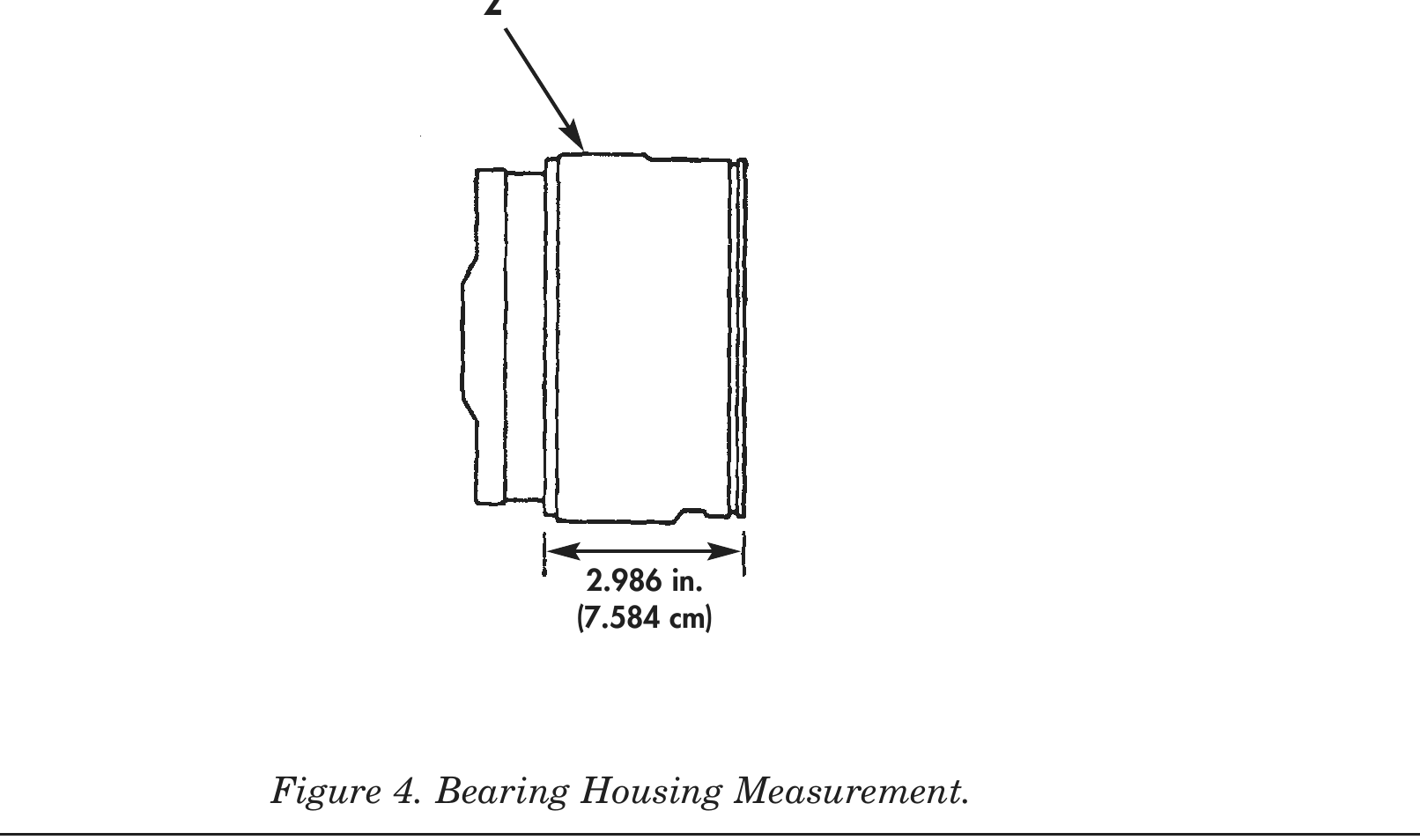
2.986 in. (7.584 cm)
1 in. (25.4 mm) 4 5
DIAL INDICATOR
LOCATION
ASSEMBLY
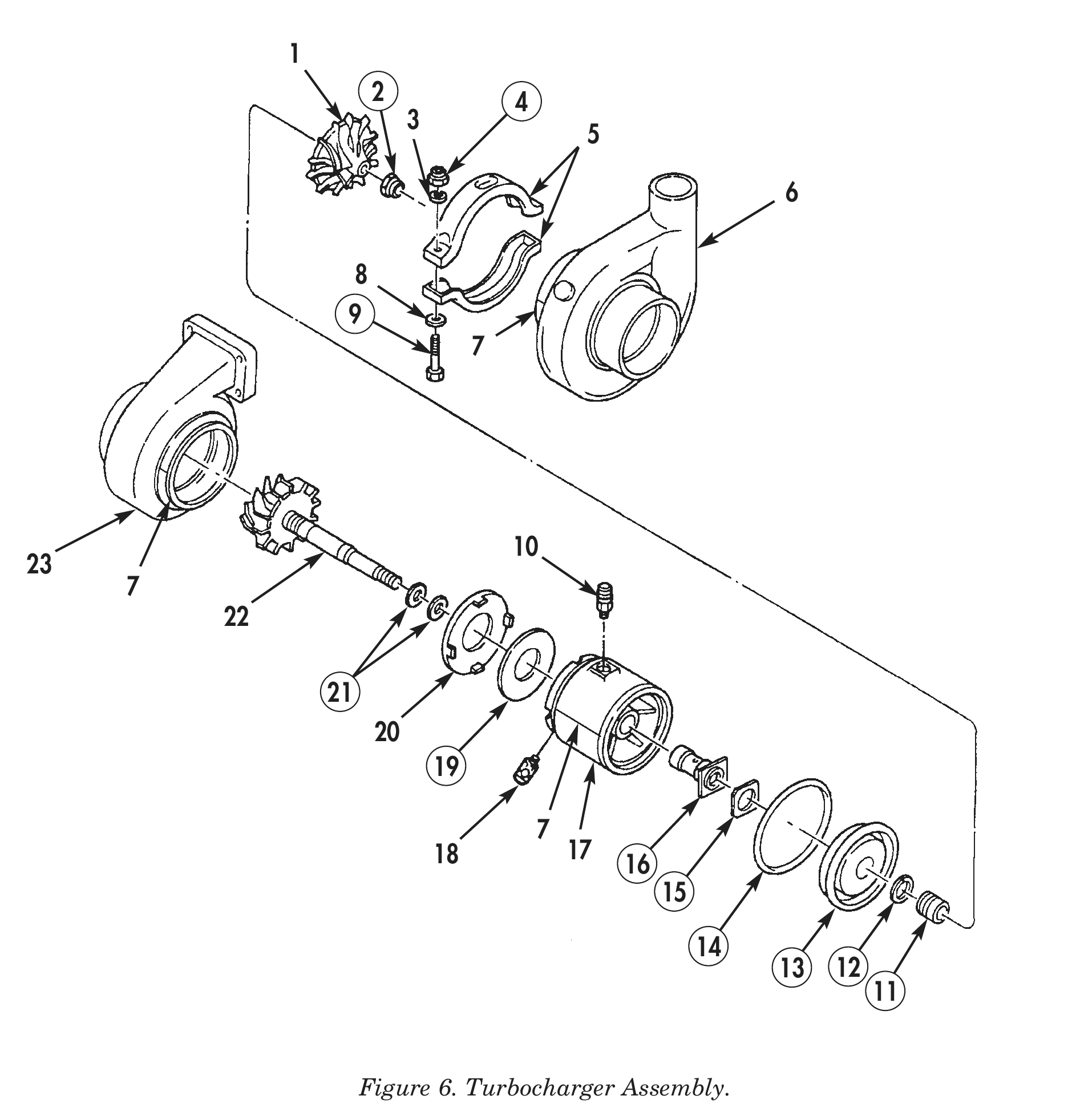
1. Apply OE/HDO 30 lubricating oil to new bearing (16) and install in bearing housing (17).
2. Bend edges of new bearing insert pad (15) over bearing housing (17). Apply OE/HDO 30 lubricating oil to bearing insert pad (15) and install on bearing (16).
3. Apply OE/HDO 30 lubricating oil to new ring seal (12) and install on new sleeve (11).
4. Install new sleeve (11) and ring seal (12), with spiral grooves facing bearing, in new diffuser plate (13) until sleeve is flush with turbocharger impeller (1) end.
5. Apply OE/HDO 30 lubricating oil to new O-ring (14) and install on diffuser plate (13).
6. Install diffuser plate (13) on bearing housing (17).
7. Position new insulated packing (19) on bearing housing (17), with flat side of insulated packing (19) facing out.
8. Align heat shield (20) locating tabs with depressions in bearing housing (17) and install heat shield (20) on bearing housing (17).
9. Install two new seals (21) on wheel and shaft (22). Rotate seal gaps 90º apart.
10. Install wheel and shaft (22) in bearing housing (17). Ensure heat shield (20) and sleeve (11) remain in position.
11. Using press, install turbocharger impeller (1) on wheel and shaft (22).
12. Install new impeller locknut (2) on wheel and shaft (22). Tighten locknut (2) 20–24 lb-ft (27–32 N•m).
13. Apply antiseize compound to turbine housing (23). Align mark (7) made on turbine housing (23) to mark (7) on bearing housing (17). Install turbine housing (23) on bearing housing (17).
14. Apply antiseize compound on impeller housing (6). Align mark (7) made on impeller housing (6) to mark (7) on bearing housing (17). Install impeller housing (6) on bearing housing (17).
15. Install V-band clamp (5) on impeller housing (6), bearing housing (17), and turbine housing (23) with two new screws (9), four washers (3) and (8), and two new locknuts (4). Tighten locknuts (4) 58–68 lb-in. (6.6–7.7 N•m).
16. Apply antiseize compound to two adapters (10) and (18) and install on bearing housing (17). Tighten adapter (10) 20–25 lb-ft (27–34 N•m). Tighten adapter (18) 50 lb-ft (68 N•m).
17. Using feeler gauge, measure clearance between turbine housing (23) and V-band clamp (5). Minimum clearance is 0.035 in. (0.889 mm). Loosen V-band clamp (5) and adjust turbine housing (23) as necessary to obtain correct clearance.
18. Using feeler gauge, measure clearance between impeller (1) and inside of impeller housing (6). Minimum clearance is 0.006–0.025 in. (0.152–0.635 mm). Loosen V-band clamp (5) and adjust impeller housing (6) as necessary to obtain correct clearance.
ASSEMBLY (Contd)
19. Using feeler gauge, measure clearance between wheel and shaft (22) and turbine housing (23). Minimum clearance is 0.005–0.043 in. (0.127–0.092 mm). Loosen V-band clamp (5) and turbine housing (23) as necessary to obtain correct clearance.
20. Using dial indicator, measure wheel and shaft (22) end play. Wheel and shaft (22) end play must be within 0.006–0.0018 in. (0.152–0.457 mm). Loosen and retighten impeller locknut (2) until correct endplay is obtained.
21. For installation of turbocharger, refer to WP 0046 00.
2 4
18 17
13 12
END OF WORK PACKAGE