MOUNTING ENGINE ON MAINTENANCE STAND
TM 9-2815-225-34&P · Work Package 0009 00
INITIAL SETUP
Tools and Special Tools                             Equipment Condition
 General mechanic’s tool kit: automotive             Engine removed from vehicle
    (Item 1, WP 0061 00)                               (WP 0007 00 or WP 0008 00).
 Maintenance and repair shop equipment:
    automotive (Item 2, WP 0061 00)                 Personnel Required
 Automotive maintenance and repair                   Assistant
    supplemental set no. 2 (Item 3, WP 0061 00)
 Maintenance stand                                  Materials/Parts
 Lifting device                                      Four screws
 Chains
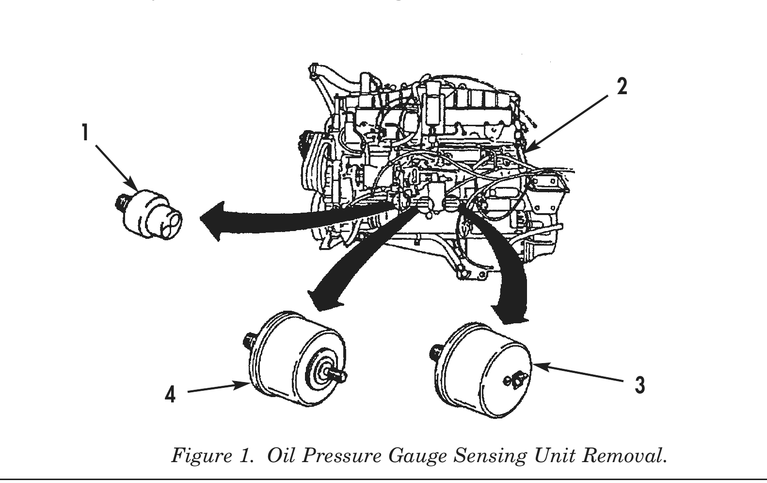
1. Remove oil pressure gauge sensing unit (4) and low oil pressure warning light sending unit (3) from cylinder block (2).
2. Remove transmission control-body heating elements ON/OFF switch (1) from cylinder block (2).
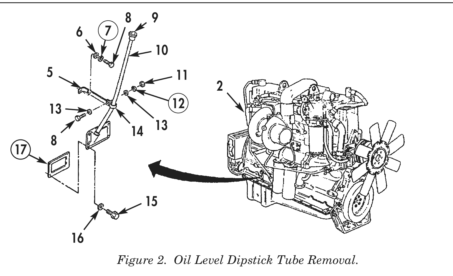
3. Remove oil level dipstick (9) from oil level dipstick tube and cover (10).
4. Remove screw (8), lockwasher (7), and washer (6) from tube brace (5). Discard lockwasher (7).
5. Remove nut (11), lockwasher (12), two washers (13), screw (8), clamp (14), and tube brace (5) from oil level dipstick tube and cover (10).
6. Remove four captive washer screws (15), washers (16), oil level dipstick tube and cover (10), and gasket (17) from cylinder block (2). Discard gasket (17).
4 3
8 9 6 7 5 11 13 12
14 13
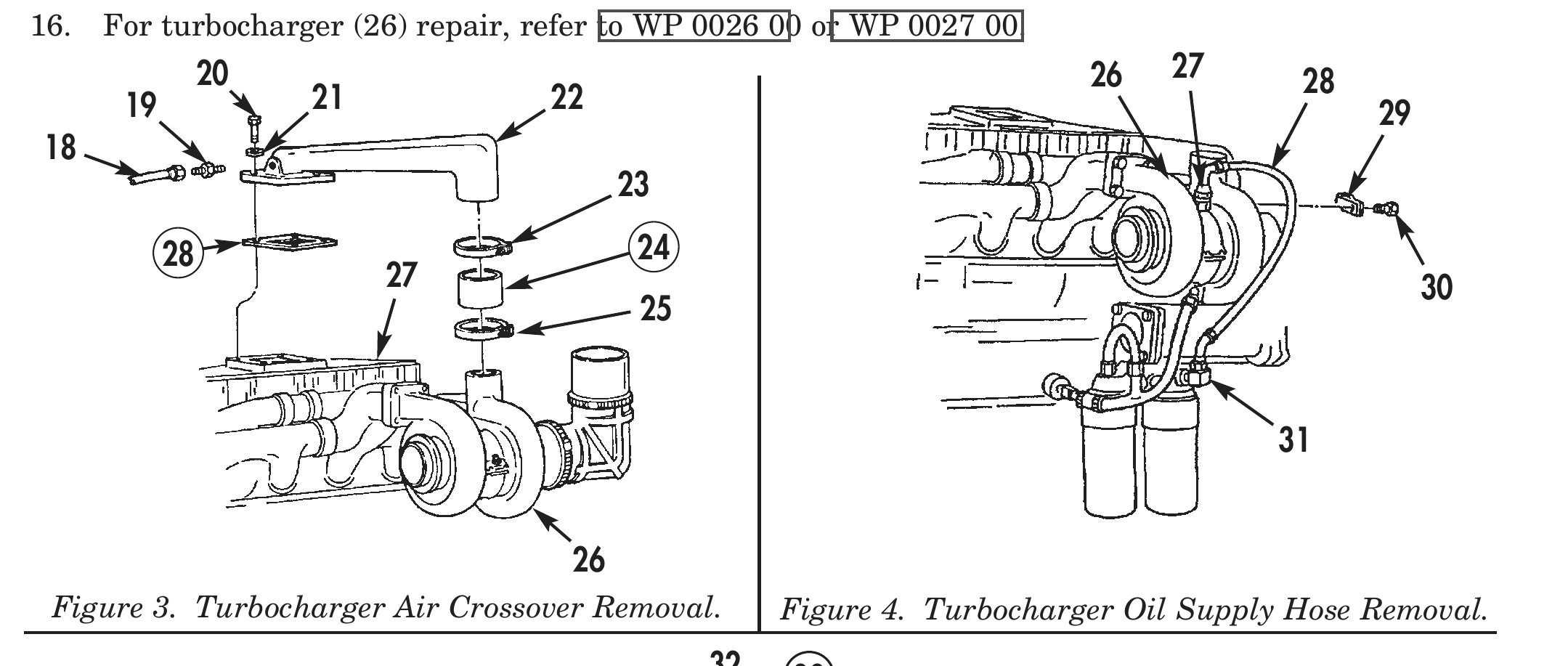
7. Loosen clamps (23) and (25) retaining turbocharger air crossover (22) and hose (24) to turbocharger (26).
8. Remove hose (18) and fitting (19) from turbocharger air crossover (22).
9. Remove four bolts (20), washers (21), turbocharger air crossover (22), hose (24) and gasket (28) from aftercooler cover (27) and turbocharger (26). Discard hose (24) and gasket (28).
10. Remove bolt (30) securing clamp (29) and turbocharger oil supply hose (28) to turbocharger adapter (27) and elbow (31).
11. Remove turbocharger oil supply hose (28) from turbocharger (26).
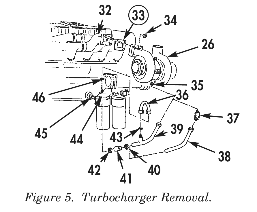
12. Loosen clamps (40) and (42), and remove oil return tube (38) from elbows (37) and (45).
13. Remove oil return tube (36) and two bushings (43) and (46) from oil return tube (39) and filter head (44).
14. Remove oil return tube (38), two clamps (40) and (42), and hose (41) from elbows (35) and (45).
15. Remove four nuts (34), turbocharger (26), and gasket (33) from exhaust manifold (32). Discard gasket (33).
16. For turbocharger (26) repair, refer to WP 0026 00 or WP 0027 00.
          20                                                                      26   27    28
19             21              22                                                                 29
28 24 27 30
Figure 3. Turbocharger Air Crossover Removal. 32 33
Figure 4. Turbocharger Oil Supply Hose Removal. 34
46 36 45 39 44 43 42 40 Figure 5. Turbocharger Removal.
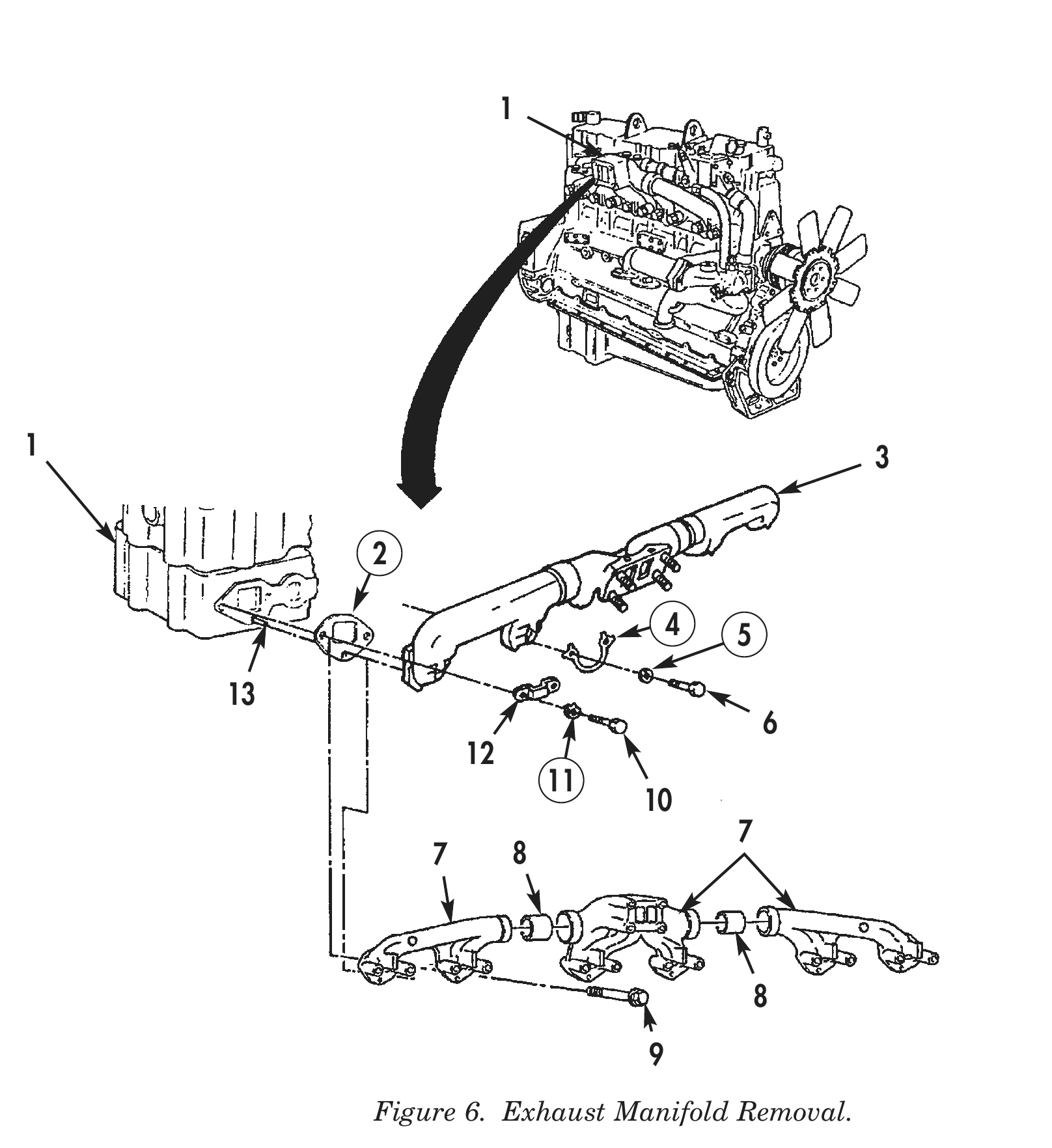
17. Bend tabs of four lockplates (4) and remove eight bolts (6), lockwashers (5), and lockplates (4) securing exhaust manifold (3) to cylinder head (1) and dowels (13). Discard lockplates (4) and lockwashers (5).
18. Bend tabs of two lockplates (11) and remove four bolts (10), lockplates (11), clamps (12), exhaust manifold (3), and six gaskets (2) from cylinder heads (1). Discard lockplates (11) and gaskets (2).
19. Remove twelve captive head screws (9), exhaust manifold (7), and six gaskets (2) from cylinder heads (1). Discard gaskets (2). Do not separate manifolds and spacer inserts (8) at this time.
20. For exhaust manifold (7) or (3) repair, refer to WP 0025 00.
1 3
4 5 7 8
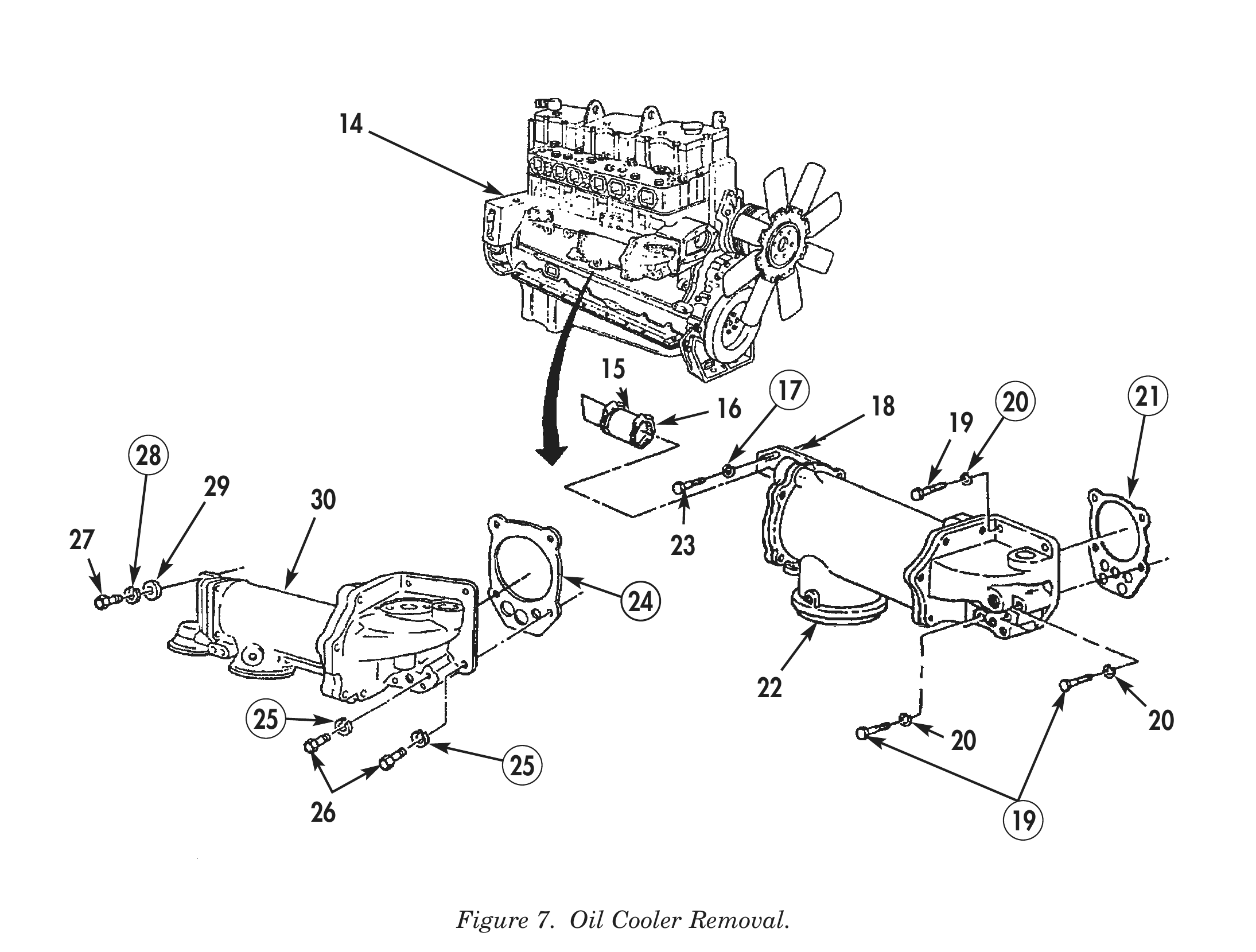
21. Remove screw (23) and lockwasher (17) securing oil cooler support bracket (18) to cylinder block (14). Discard lockwasher (17).
22. Loosen clamp (16) and remove water transfer hose (15) from oil cooler (22).
23. Remove five screws (19), lockwashers (20), oil cooler (22), and gasket (21) from cylinder block (14). Discard lockwashers (20) and gasket (21).
24. Remove two screws (27), lockwashers (28), and washers (29) securing rear of oil cooler (30) to cylinder block (14). Discard lockwashers (28).
25. Remove six screws (26), lockwashers (25), oil cooler (30), and gasket (24) from cylinder block (14). Discard lockwashers (25) and gasket (24).
26. For oil cooler (30) or (22) repair, refer to WP 0021 00.
17 20 21 16 18 27 23
25 20 26 19
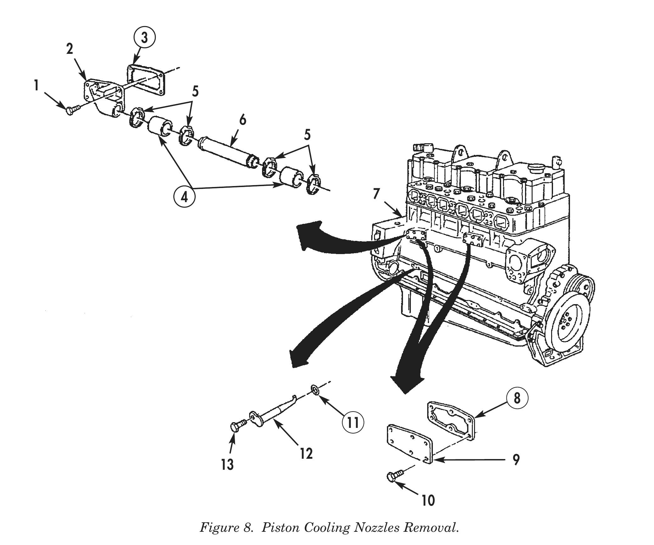
27. Loosen four clamps (5) and remove two water transfer hoses (4) and water transfer tube (6) from water transfer flange (2). Discard hoses (4).
28. Remove six screws (1), water transfer flange (2), and gasket (3) from cylinder block (7). Discard gasket (3).
29. Remove twelve screws (10), two water header covers (9), and gaskets (8) from cylinder block (7). Discard gaskets (8).
30. Remove six screws (13) and piston cooling nozzles (12) from cylinder block (7).
31. Remove six O-rings (11) from piston cooling nozzles (12) Discard O-rings (11).
1 5
4 7
12 9
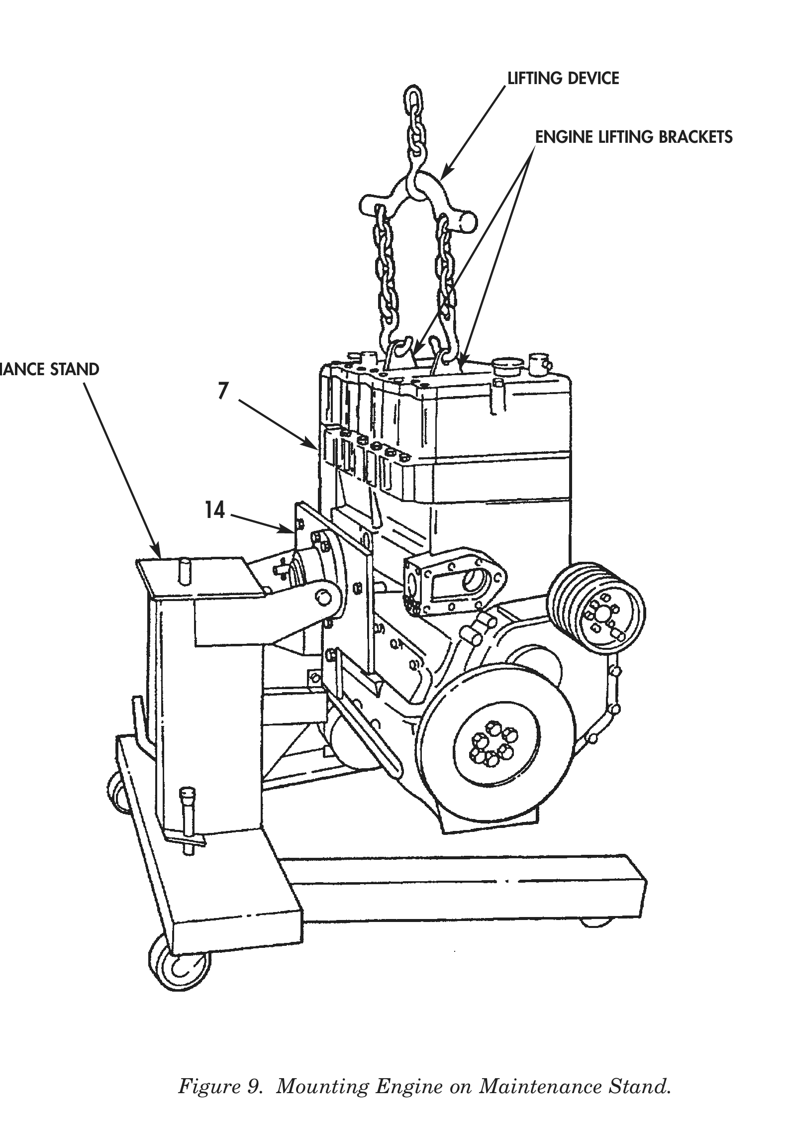
32. Install right side of cylinder block (7) on maintenance stand with four screws (14).
33. Remove engine lifting device from engine lifting brackets.
LIFTING DEVICE
ENGINE LIFTING BRACKETS
MAINTENANCE STAND
END OF WORK PACKAGE