FUEL PUMP MAIN HOUSING
TM 9-2815-225-34&P · Work Package 0039 00
DISASSEMBLY, CLEANING AND INSPECTION, ASSEMBLY
INITIAL SETUP
Tools and Special Tools                                Equipment Condition
 General mechanic’s tool kit: automotive                Fuel pump main housing removed from fuel
    (Item 1, WP 0061 00)                                  pump (WP 0033 00).
 Maintenance and repair shop equipment:
    automotive (Item 2, WP 0061 00)
 Automotive maintenance and repair
    supplemental set no. 2 (Item 3, WP 0061 00)
 Press
 AFC barrel puller (Item 69, WP 0061 00)

Material/Parts
 Lubricating oil (Item 19, WP 0060 00)
 Retaining ring (Item 1, Table 22, WP 0062 00)
 O-ring (Item 2, Table 22, WP 0062 00)
 Throttle shaft ball
   (Item 3, Table 22, WP 0062 00)
 O-ring (Item 4, Table 22, WP 0062 00)
 O-ring (Item 5, Table 22, WP 0062 00)
 Cap seal ring (Item 6, Table 22, WP 0062 00)
 Retaining ring (Item 7, Table 22, WP 0062 00)
 O-ring (Item 8, Table 22, WP 0062 00)
 O-ring (Item 9, Table 22, WP 0062 00)
 O-ring (Item 10, Table 22, WP 0062 00)
 O-ring (Item 11, Table 22, WP 0062 00)
 Gasket washer
   (Item 12, Table 22, WP 0062 00)
 Bellows (Item 13, Table 22, WP 0062 00)
DISASSEMBLY
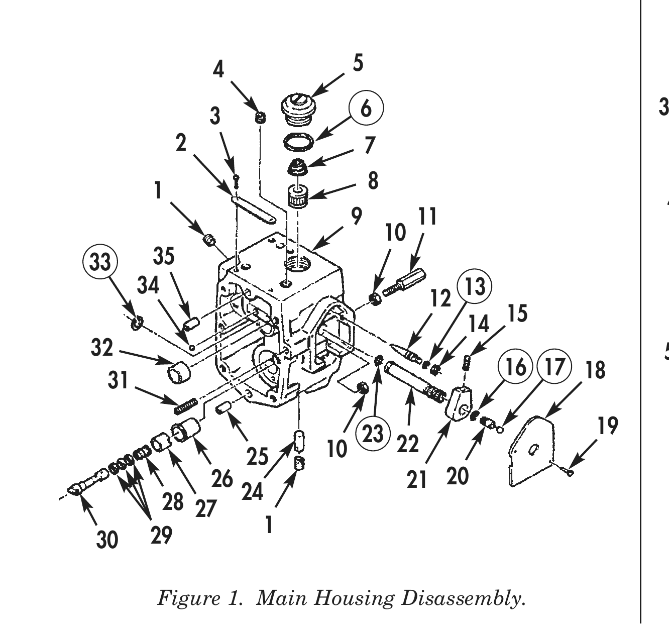
1. Remove two drive screws (19) from throttle shaft cover (18).
2. Remove retaining ring (33) from throttle shaft (22). Discard retaining ring (33).
3. Remove throttle shaft (22) and O-ring (23) from housing (9). Discard O-ring (23).
4. Remove throttle shaft ball (17) from throttle shaft (22). Discard throttle shaft ball (17).
5. Remove fuel adjusting screw (20) and O-ring (16) from throttle shaft (22). Discard O-ring (16).
6. Remove setscrew (15) and throttle shaft (22) from stop (21).
7. Loosen nut (14) from Air Fuel Control (AFC) needle valve (12).
8. Remove AFC needle valve (12) and O-ring (13) from housing (9). Discard O-ring (13).
9. Remove nut (14) from AFC needle valve (12).
10. Remove threaded stud (11) secured with jamnut (10) from housing (9).
11. Remove jamnut (10) securing tapered stud (31) from housing (9).
12. Remove filter screen cap (5), cap seal ring (6), filter spring (7), and fuel filter screen (8) from housing (9). Discard cap seal ring (6).
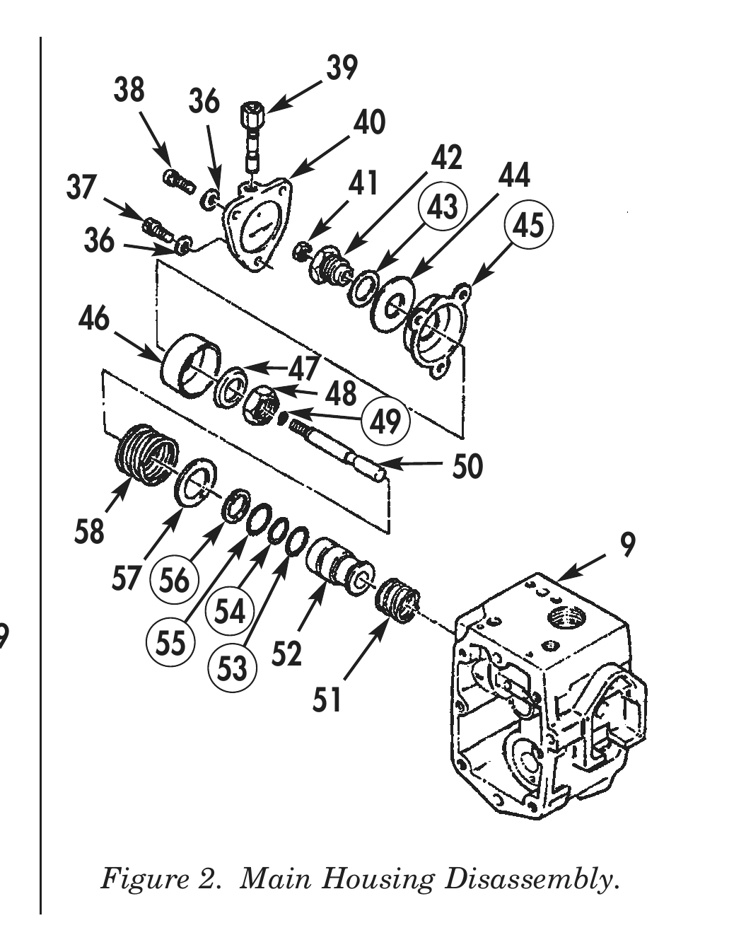
13. Remove check valve (39) from fuel control cover (40).
14. Remove two screws (38), drilled head screw (37), and three washers (36) from fuel control cover (40).
15. Move bellows (45) away from sealing surface on housing (9) and remove with attached parts.
16. Remove spring (58), AFC shim (57), and retaining ring (56) from housing (9). Discard retaining ring (56).
17. Using AFC barrel puller, remove barrel (52), and three O-rings (53), (54), and (55) from housing (9). Discard O-rings (53), (54), and (55).
18. Remove barrel spring (51) from housing (9).
19. Remove jamnut (41) from throttle plunger (50).
20. Remove throttle plunger (50) and O-ring (49) from air fuel control piston insert (42). Discard O-ring (49).
21. Remove nut (48) securing air fuel control piston insert (42) and remove piston spacer (47), AFC piston (46), bellows (45), retainer washer (44), and gasket washer (41) from air fuel control piston insert (42). Discard gasket washer (43) and bellows (45).
22. Remove governor plunger (30), three shims (29), and torque spring (28) from housing (9).
23. Remove torque spring (28) and three shims (29) from governor plunger (30).
24. Remove five pipe plugs (1) and (4) and roll pin (24) from housing (9).
25. Remove spring pack (27) and governor barrel (26) from housing (9).
26. Remove tachometer drive bushing (32), two AFC plug balls (34), and two dowels (25) and (35) from housing (9).
27. Remove two screws (3) and nameplate (2) from housing (9).
CLEANING AND INSPECTION

 1.    For general parts cleaning information, refer to CLEANING, WP 0051 00.
 2.    For general parts inspection information, refer to INSPECTION, WP 0051 00.
                                                               NOTE
                           Replace any part that does not pass visual inspection or that is
                           outside specified wear limits.
 3.    Inspect tachometer drive bushing (32) for scoring, burrs, and other damage.
 4.    Using vernier caliper, measure inside diameter of tachometer drive bushing (32). Maximum inside
       diameter is 0.752 in. (19.10 mm).
 5.    Inspect governor barrel (26) for scoring, burrs, and other damage.
 6.    Using outside micrometer, measure governor barrel (26) diameter of bore in housing (9) and
       outside diameter of governor barrel (26). Diameter of bore should be 0.002 in. (0.051 mm) smaller
       than governor barrel (26) outside diameter.
 7.    Inspect governor plunger (30), and shims (29) for scoring, burrs, and other damage.
 8.    Inspect housing (1) and nameplate (2) for scoring, burrs, and other damage.
 9.    Inspect fuel filter screen (8) for holes and embedded metal particles in mesh.
10.    Inspect dowels (25) and (35) for damage.

                                                                                                       39
                                                                                  38        36
                      4               5                                                                   40
                                                                                                                 42
                                      6                                    37                             41           44
                      3                                                                                          43
                  2                       7                                  36                                        45

             1                            8
                                                                             46
                                      9            11
                                              10                                                  47
  33         35                                                                                        48
                                                                                                            49
            34
                                                    12 13                                                         50
                                                       14 15
      32                                                                   58
                                                           16 17 18                                                              9
       31                                                                         57 56
                                                                                             54
                                      23 22                           19               55
                          25     10                                                          53 52
                  26                               21 20                                             51
              28 27 24
             29       1
      30

             Figure 1. Main Housing Disassembly.                                Figure 2. Main Housing Disassembly.
ASSEMBLY
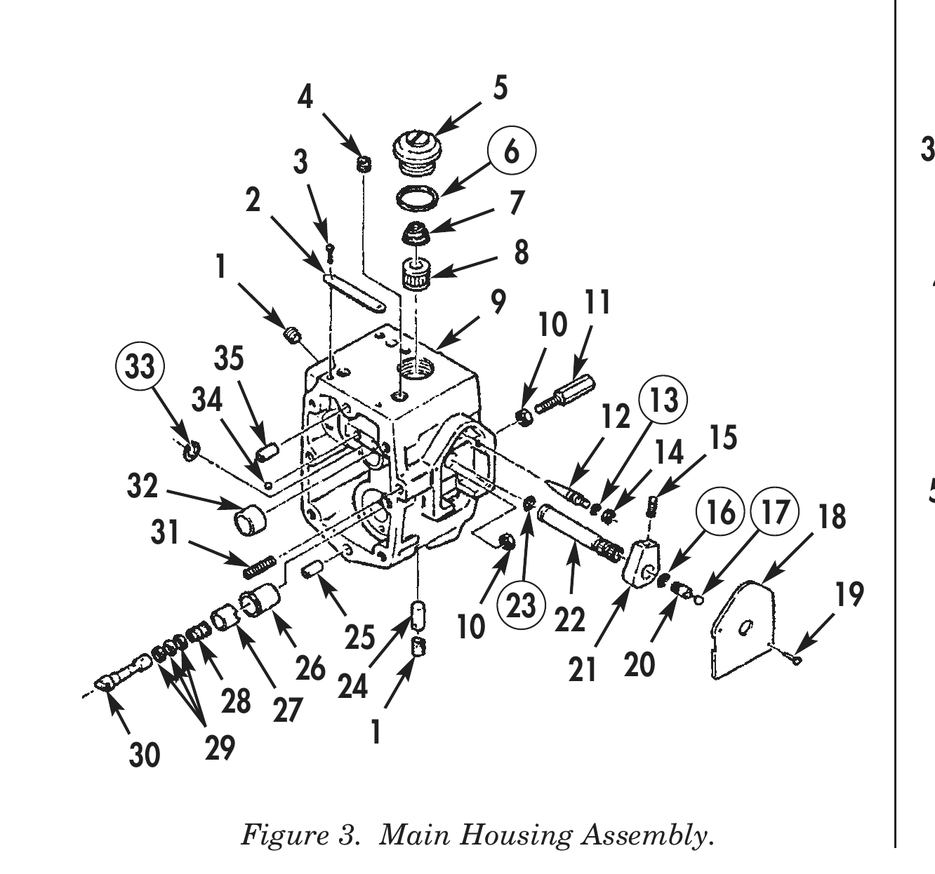
1. Install two screws (3) and nameplate (2) on housing (9).
2. Install two dowels (25) and (35), two AFC plug balls (34), and tachometer drive bushing (32) on housing (9).
3. Install governor barrel (26) and spring pack (27) on housing (9).
4. Install five pipe plugs (1) and (4), and roll pin (24) on housing (9). Tighten pipe plugs (1) and (4) 5–8 lb-ft (7–11 N•m).
5. Install torque spring (28) and three shims (29) on governor plunger (30).
6. Install governor plunger (30) on housing (9).
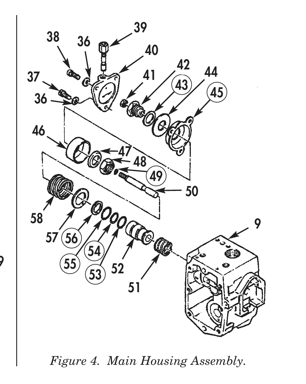
7. Install new gasket washer (43), retainer washer (44), new bellows (45), AFC piston (46), piston spacer (47), and nut (48) on air fuel control piston insert (42). Tighten nut (48) 30–40 lb-ft (41–54 N•m).
8. Apply lubricating oil to new O-ring (49) and install throttle plunger (50) on air fuel control piston insert (42). Ensure that threaded end of throttle plunger (50) is flush with outer edge of piston insert (42).
9. Tighten jamnut (41) on throttle plunger (50) until finger-tight.
10. Install barrel spring (51) in housing (9).
11. Apply lubricating oil to three new O-rings (53), (54), and (55) and install O-rings (53), (54), and (55) with spring (50) on barrel (52).
12. Using press, install barrel (52) in housing (9) and secure with new retaining ring (56).
13. Apply 10 lb (4.54 kg) of load on spring (58) and AFC shim (57).
14. Compress spring 0.300 in. (7.62 mm) more than dimension of step 13 and install AFC shim (57) and spring (58) on housing (9).
15. Install bellows (45) down between AFC piston (46) and housing (9) and line up holes in bellows (45) with holes in housing (9). Ensure bellows (45) is flat where it touches housing (9).
16. Install fuel control cover (40) on bellows (45) and housing (9) with two screws (38), drilled head screw (37), and three washers (36). Do not tighten screws (38).
17. Ensure check ball is loose and hole near bottom of check valve (39) is not plugged. Turn check valve (39) on top of fuel control cover (40). Tighten fuel control cover (40) 5 lb-ft (7 N•m).
ASSEMBLY (Contd)

18.    Install fuel filter screen (8), filter spring (7), new cap seal ring (6), and filter screen cap (5) on
       housing (9). Tighten filter screen cap (5) 8–12 lb-ft (11–16 N•m).
19.    Install tapered stud (31) with jamnut (10) and threaded stud (11) on housing (9).
20.    Apply lubricating oil to new O-ring (13) and install AFC needle valve (12) on housing (9) until
       AFC needle valve (12) bottoms out.
21.    Install throttle shaft (22) on stop (21) and secure with setscrew (15). Do not tighten setscrew (15)
       at this time.
22.    Apply lubricating oil to new O-ring (16) securing fuel adjusting screw (20), and install O-ring (16)
       on throttle shaft (22) about six rotations. Ensure fuel hole in throttle shaft (22) is open.
23.    Apply lubricating oil to new O-ring (23) and install throttle shaft (22) in housing (9) with
       counterbore of fuel port facing down. Ensure setscrew (15) in stop (21) faces upward. Tighten
       setscrew (15) 7–9 lb-ft (9–12 N•m).
                                                                NOTE
                           New throttle shaft ball, throttle shaft cover, and two drive
                           screws will be installed after fuel pump has been calibrated.
24.    Install new retaining ring (33) on end of throttle shaft (22).
25.    Install fuel pump main housing to fuel pump (WP 0040 00).

                                                                                                         39
                                                                                    38        36
                      4               5                                                                     40
                                                                                                                   42
                                      6                                        37                           41           44
                      3                                                                                            43
                  2                       7                                     36                                       45

             1                            8
                                                                               46
                                      9            11
                                              10                                                    47
  33         35                                                                                          48
            34                                                                                                49
                                                    12 13                                                           50
                                                       14 15
      32                                                                       58
                                                             16 17 18                                                              9
       31                                                                           57 56
                                                                                               54
                                      23 22                            19                55
                          25     10                                                            53 52
                 26                                21 20                                               51
             28 27 24
            29       1
      30

                 Figure 3. Main Housing Assembly.                                    Figure 4. Main Housing Assembly.

END OF WORK PACKAGE