REMOVING ENGINE FROM MAINTENANCE STAND
TM 9-2815-225-34&P · Work Package 0046 00
INITIAL SETUP
Tools and Special Tools                               Material/Parts (Contd)
 General mechanic’s tool kit: automotive               Lockwasher (Item 16, Table 31, WP 0062 00)
    (Item 1, WP 0061 00)                               Lockwasher (Item 17, Table 31, WP 0062 00)
 Maintenance and repair shop equipment:
    automotive (Item 2, WP 0061 00)                   Equipment Condition
 Automotive maintenance and repair                     Engine mounted on maintenance stand
    supplemental set no. 2 (Item 3, WP 0061 00)          (WP 0009 00).
 Maintenance stand
 Chains                                               References
                                                       TM 9-2320-273-20
Material/Parts                                         TM 9-2320-283-20
 Gasket (Item 1, Table 31, WP 0062 00)
 Two water transfer hoses
   (Item 2, Table 31, WP 0062 00)
 Two gaskets (Item 3, Table 31, WP 0062 00)
 Six O-rings (Item 4, Table 31, WP 0062 00)
 Gasket (Item 5, Table 31, WP 0062 00)
 Five lockwashers
   (Item 6, Table 31, WP 0062 00)
 Lockwasher (Item 7, Table 29, WP 0062 00)
 Six lockwashers
   (Item 8, Table 31, WP 0062 00 00)
 Three gaskets (Item 9, Table 31, WP 0062 00)
 Four lockplates
   (Item 10, Table 31, WP 0062 00)
 Four lockplates
   (Item 11, Table 31, WP 0062 00)
 Gasket (Item 12, Table 31, WP 0062 00)
 Hose (Item 13, Tale 31, WP 0062 00)
 Gasket (Item 14, Table 31, WP 0062 00)
 Gasket (Item 15, Table 31, WP 0062 00)
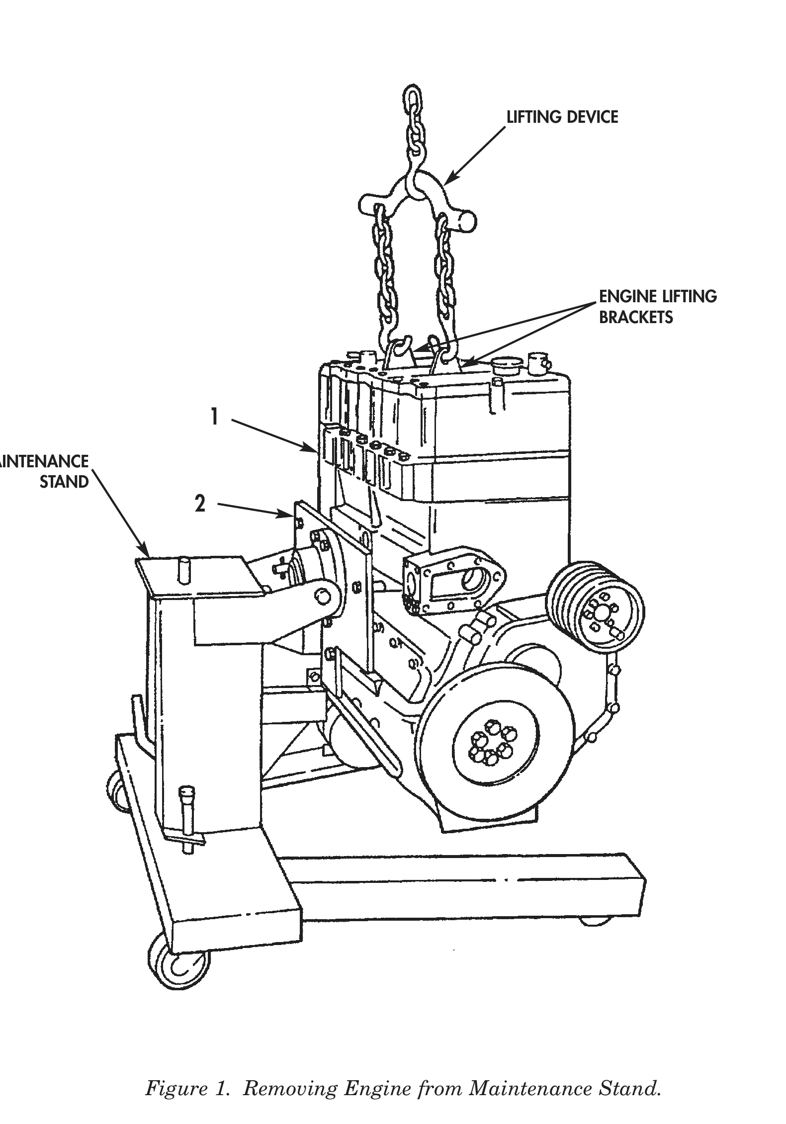
1. Install lifting device on engine lifting brackets.
2. Raise engine (1) just enough to take weight off maintenance stand.
3. Remove four mounting screws (2) securing engine (1) to maintenance stand.
4. Raise engine (1) from maintenance stand and support engine (1) on suitable blocks.
LIFTING DEVICE
ENGINE LIFTING
BRACKETS
MAINTENANCE
STAND
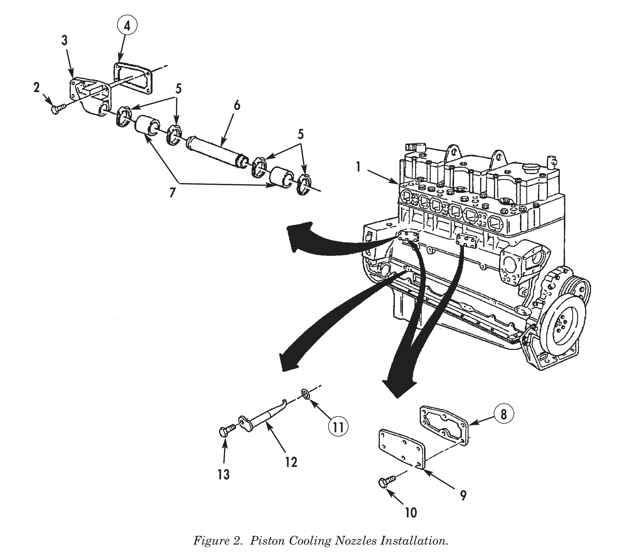
5. Install new gasket (4) and water transfer flange (3) on cylinder block (1) with six screws (2). Tighten screws (2).
6. Install water transfer tube (6) and two new water transfer hoses (7) on water transfer flange (3) with four clamps (5).
7. Install water head covers (9) and two new gaskets (8) on cylinder block (1) with twelve screws (10). Tighten screws (10).
8. Apply lubricating oil to six new O-rings (11) and position O-rings (11) on piston cooling nozzles (12).
9. Install six piston cooling nozzles (12) on cylinder block (1) with six screws (13). Tighten screws (13) 140 lb-in (16 N•m).
10. Install the following components on engine (1). Refer to TM 9-2320-273-20 or TM 9-2320-283-20.
a. Power steering pump and reservoir
b. Water pump and drivebelts
c. Fan brace, bracket, and spacers
d. Fan, fan clutch, and fan clutch drivebelts
e. Engine wiring harness
f. Ether quick-start cylinder, valve, safety switch, and thermostat
g. Modulator bracket and accelerator return spring
h. Air compressor governor and air lines
i. Air compressor intake tube
j. Air compressor discharge hose
k. Water bypass tube
l. Water pump-to-radiator connection
m. Water pump bypass hose
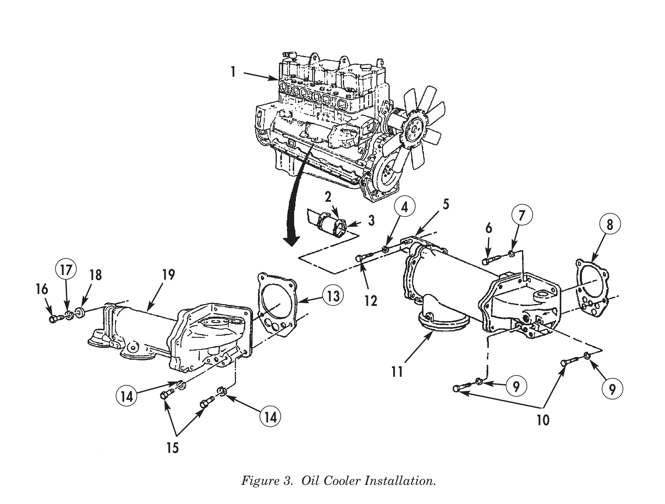
11. Install oil cooler (11) and new gasket (8) on cylinder block (1) with five screws (6) and (10), and five new lockwashers (7) and (9). Tighten screws (6) and (10) 30–35 lb-ft (41–48 N•m).
12. Install oil transfer hose (2) on oil cooler (11) with clamp (3). Tighten clamp (3) at water transfer hose (2).
13. Install oil cooler support bracket (5) to cylinder block (1) with screw (12) and new lockwasher (4). Tighten screw (12) 30–35 lb-ft (41–48 N•m).
14. Install oil cooler (19) and new gasket (13) on cylinder block (1) with six screws (15) and (16), washers (18), and new lockwashers (14) and (17). Tighten screws (15) and (16) 30–35 lb-ft (41–48 N•m).
15. Install the following components on cylinder block (1). Refer to TM 9-2320-273-20 or TM 9-2320-283-20.
a. Engine oil filter elements
b. Lower water transfer tube
c. Alcohol evaporator
d. Engine retarder microswitch
e. Water manifolds
f. Thermostat and thermostat housing
g. Engine temperature sending units and fuel line fittings.
h. Fan clutch air valve and air lines
i. Water transfer tube and bracket
j. Air compressor cooling tube
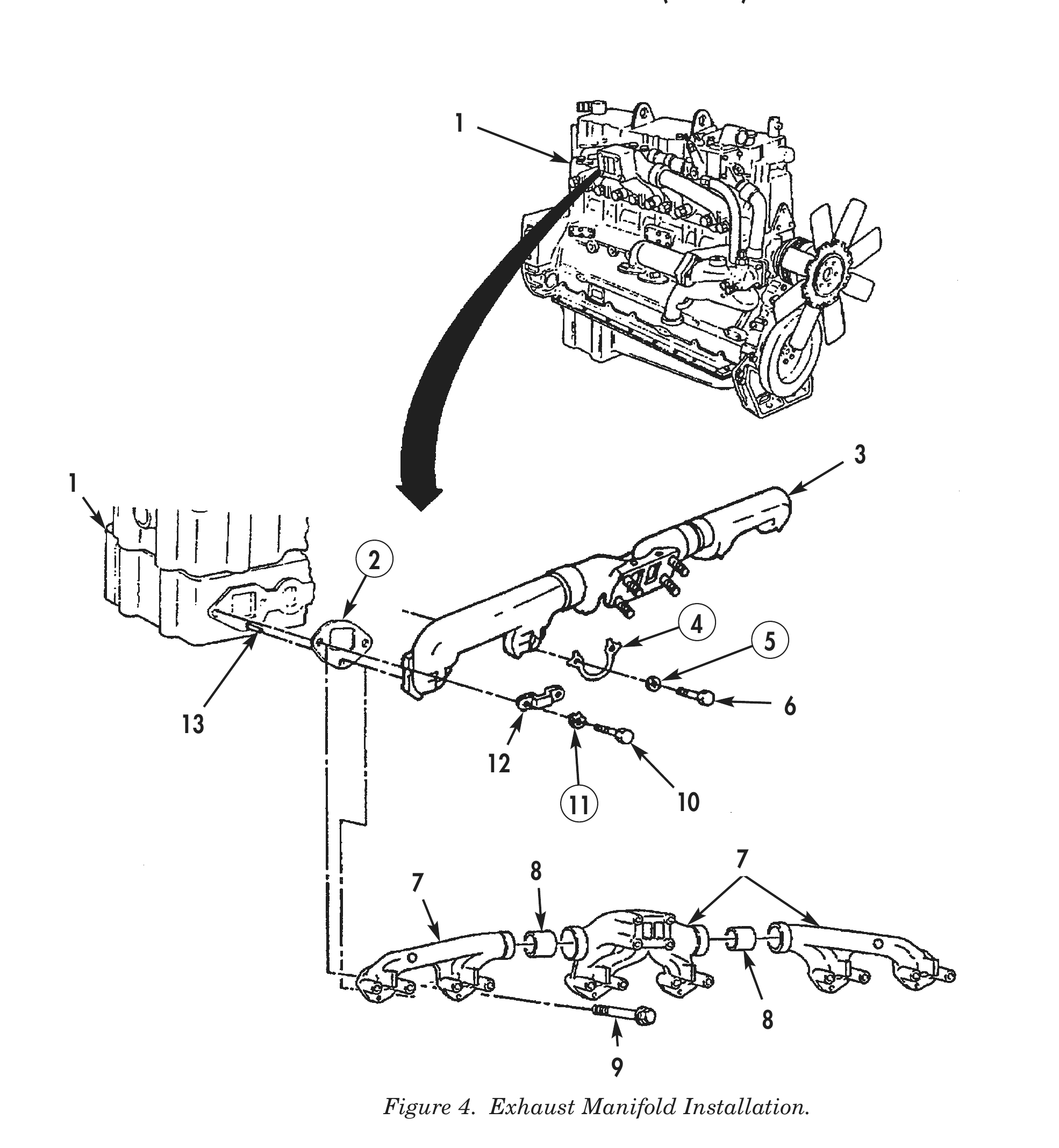
16. Install three new gaskets (2) on cylinder block (1) with word OUT facing exhaust manifold (3) or (7).
17. Apply antiseize compound to threads of screws (10).
18. Install exhaust manifold (3), two clamps (12), four new lockplates (11), and dowels (13) on cylinder block (1) with four screws (10). Do not tighten screws (10).
19. Install four new lockplates (4) on exhaust manifold (3) with four screws (6) and new lockwashers (5). Tighten screws (6) and (10) alternately and evenly 15–20 lb-ft (20–27 N•m) and then 40–45 lb-ft (54–61 N•m).
20. Apply antiseize compound to threads of screws (9).
21. Install exhaust manifold (7) and spacer inserts (8) on cylinder block (1) with twelve screws (9). Tighten screws (9) alternately and evenly 15–20 lb-ft (20–27 N•m) and then 40–45 lb-ft (54–61 N•m).
22. Install the following components on cylinder block (1). Refer to TM 9-2320-273-20 or TM 9-2320-283-20.
a. Water filter and bracket
b. Water shutoff valves and hoses
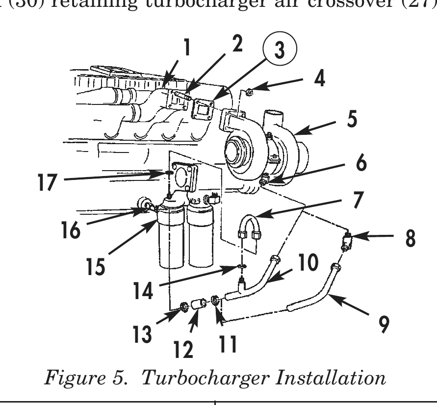
23. Apply antiseize compound to threads of studs (2) and install new gasket (3) on exhaust manifold studs (2).
24. Install turbocharger (5) on exhaust manifold (1) with four nuts (4). Tighten nuts (4) 20–25 lb-ft (27–34 N•m).
25. Install oil return tube (9) and hose (12) on elbows (8) and (16) with two clamps (11) and (13). Tighten clamps (11) and (13) 35–45 lb-ft (48–61 N•m).
26. Install oil return tube (10) and hose (12) on elbows (6) and (16) with two clamps (11) and (13). Tighten clamps (11) and (13) 35–45 lb-ft (48–61 N•m).
27. Install oil return tube (7) and two bushings (14) and (17) on filter head (15) and oil return tube (10). Tighten fittings on oil return tube (7) 50–60 lb-ft (68–81 N•m).
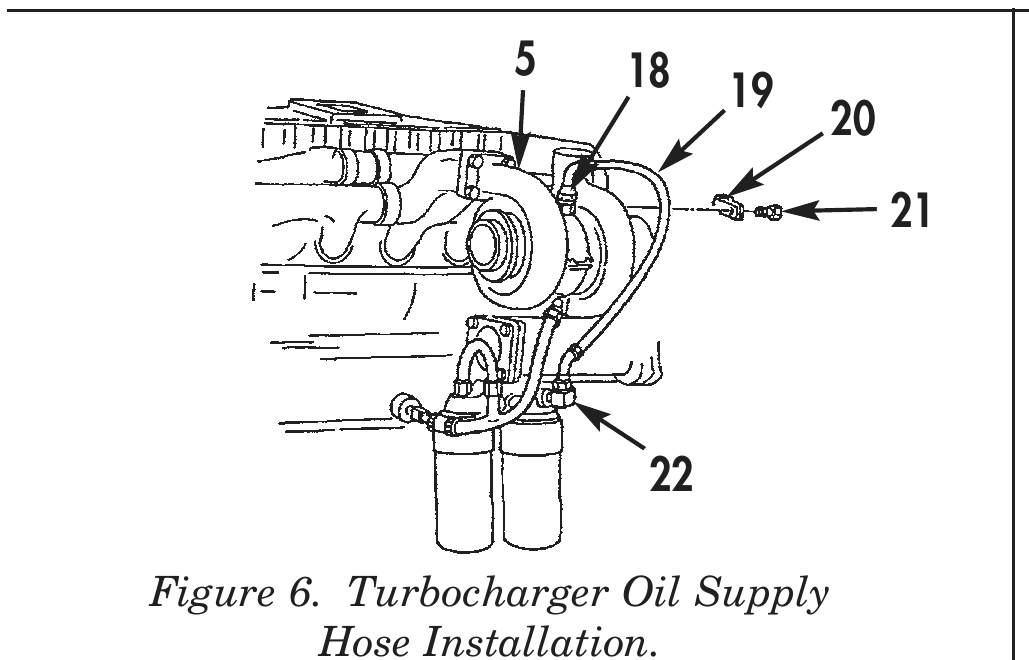
28. Install oil supply hose (19) on adapter (18) and elbow (22). Tighten fittings on oil supply hose (19) 50–60 lb-ft (68–81 N•m).
29. Install clamp (20) and screw (21) on turbocharger (5). Tighten screw (21) 14 lb-ft (19 N•m).
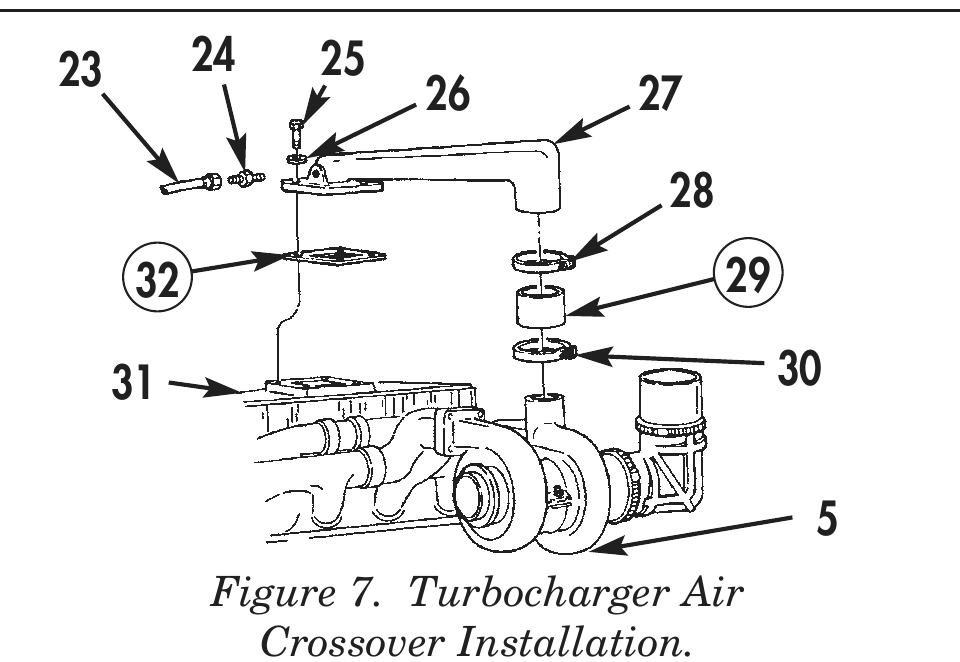
30. Install four bolts (25), washers (26), turbocharger air crossover (27), clamps (28) and (30), new hose (29), and new gasket (32) on aftercooler cover (31).
31. Install hose (23) and fitting (24) on turbocharger air crossover (27).
32. Tighten clamps (28) and (30) retaining turbocharger air crossover (27) and hose (29) to turbocharger (5). 1 2 3 16 8 15 10 13 9 12 11 Figure 5. Turbocharger Installation
5     18                                   23            24           25
              19                                                           26   27
21 28 32 29
31 30
Figure 6. Turbocharger Oil Supply Hose Installation.
Figure 7. Turbocharger Air Crossover Installation.
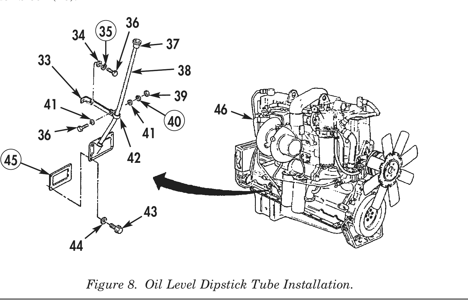
33. Install new gasket (45), and oil level dipstick tube and cover (38) on cylinder block (46) with four washers (44) and captive washer screws (43). Tighten captive washer screws (43) 30–35 lb-ft (41–48 N•m).
34. Install tube brace (33) and clamp (42) on oil level dipstick tube and cover (38) with two washers (41), screw (36), new lockwasher (40), and nut (39). Tighten nut (39).
35. Install tube brace (33) on cylinder block (46) with screw (36), washer (34), and new lockwasher (35).
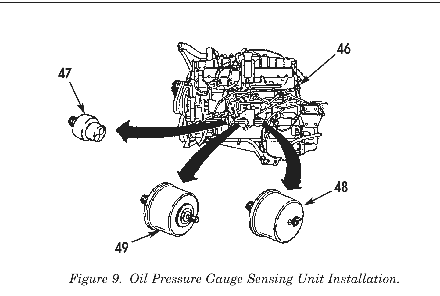
36. Install transmission control-body heating elements ON/OFF switch (47) on cylinder block (46).
37. Install oil pressure gauge sending unit (48) and low oil pressure warning light sending unit (49) on cylinder block (46).
34 35 41 46 36 41 45 42
END OF WORK PACKAGE