ILLUSTRATED LIST OF MANUFACTURED ITEMS
TM 9-2815-225-34&P · Work Package 0052 00
SCOPE
This Work Package (WP) includes complete instructions for making items authorized to be manufactured or fabricated.
EXPLANATION OF THE ILLUSTRATIONS OF MANUFACTURED ITEMS
All instructions needed by maintenance personnel to manufacture the item are included on the illustrations. All bulk materials needed for manufacture of an item are listed by part number or national stock number in a tabular list on the illustration.
Table 1. Manufactured Items Part Number Table of Contents.
ITEM
              NSN              PART NO.                    ITEM               PAGE NO.
NO.

 1.     6680-01-108-7410       199453                Oil level dipstick       0052 00-2

                                                Flywheel housing guide pin
 2.     5305-00-795-9336       204165                                         0052 00-3
                                                     (two required)
                                              Vibration damper guide pin
 3.     5305-01-145-8380       S-189-B                                        0052 00-4
(two required)
39.13 in. (99.39 cm)
H L
36.31 in. 2.06 in. (92.23 cm) (5.23 cm)
PROCEDURE:
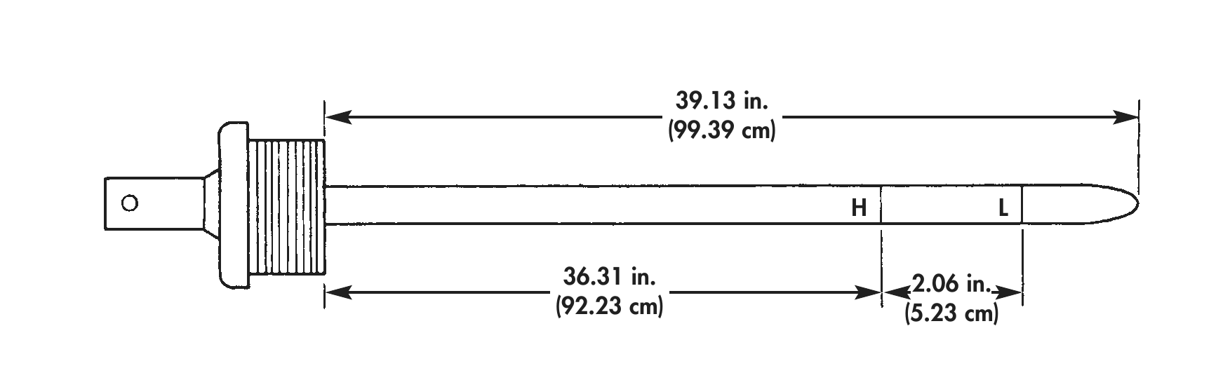
1. Using roller, measure 39.13 in. (99.39 cm) down dipstick from bottom of rubber stopper and cut dipstick. Round off tip of dipstick.
2. Measure 36.31 in. (92.23 cm) down dipstick from bottom of rubber stopper and etch a line on dipstick at this length. Etch an “H” next to this line.
3. Measure 2.06 in. (5.23 cm) down dipstick from line etched in step 3 and etch another line at this length. Etch an “L” next to this line.
4. Etch part number 199453 on dipstick near rubber stopper.
ITEM 1. OIL LEVEL DIPSTICK
0.125 in. (3.17 mm)
0.06 in. (1.57 mm)
PROCEDURE:
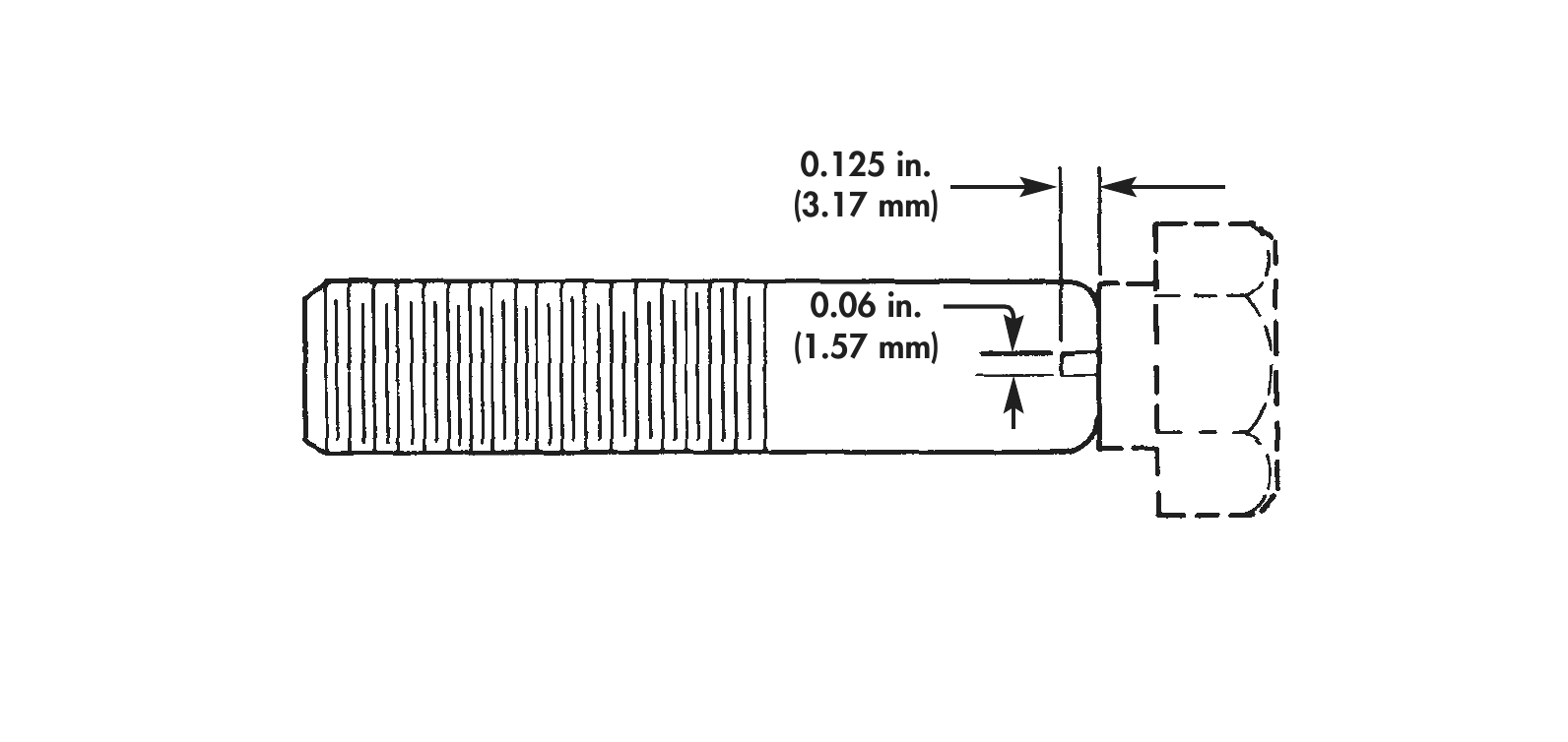
1. Using hack saw, cut off head of screw.
2. Round off edge of non-threaded end of screw.
3. Using press, cut a slit approximately 0.06 in. (1.57 mm) wide and 0.125 in. (3.17 mm) deep in non-threaded end of screw.
4. Using grinding wheel, remove any burrs after cutting.
ITEM 2. FLYWHEEL HOUSING GUIDE PIN
0.125 in. (3.17 mm)
0.06 in. (1.57 mm)
PROCEDURE:
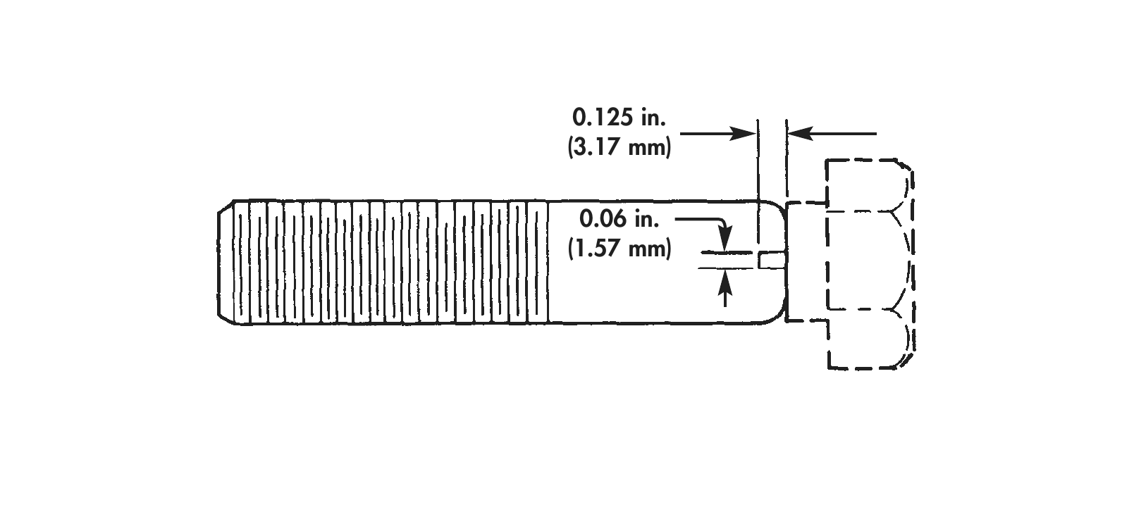
1. Using hack saw, cut off head of screw.
2. Round off edge of non-threaded end of screw.
3. Using press, cut a slit approximately 0.06 in. (1.57 mm) wide and 0.125 in. (3.17 mm) deep in non-threaded end of screw.
4. Using grinding wheel, remove any burrs after cutting.
ITEM 3. VIBRATION DAMPER GUIDE PIN
END OF WORK PACKAGE