CYLINDER BLOCK COMPONENTS REMOVAL
TM 9-2815-225-34&P · Work Package 0012 00
FLYWHEEL, FLEXPLATE, AND FLYWHEEL HOUSING; OIL PAN; FRONT GEAR COVER; PISTONS AND
CONNECTING RODS; CAMSHAFT FOLLOWERS; CRANKSHAFT AND MAIN BEARINGS
INITIAL SETUP
Tools and Special Tools
 General mechanic’s tool kit: automotive
    (Item 1, WP 0061 00)
 Maintenance and repair shop equipment:
    automotive (Item 2, WP 0061 00)
 Automotive maintenance and repair
    supplemental set no. 2 (Item 3, WP 0061 00)
 Stud 5/8-18x6 in.
 Jack screw 1/2-13x6 in.
 Camshaft pilot tool (Item 62, WP 0061 00)
 Main bearing cap puller (Item 68, WP 0061 00)
 Lifting device

Equipment Condition
 Engine mounted on maintenance stand
   (WP 0009 00).
 Engine accessories removed (WP 0010 00).
 Cylinder heads removed (WP 0011 00).

Personnel Required
 Two Assistants
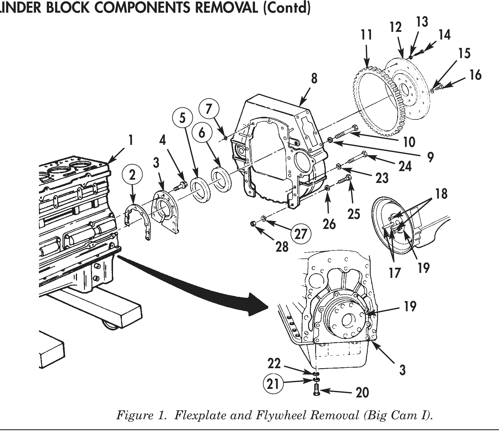
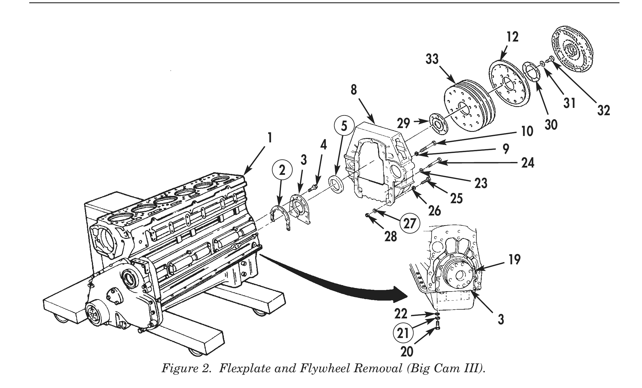
FLYWHEEL, FLEXPLATE, AND FLYWHEEL HOUSING
1. Remove six bolts (16) and washers (15) from flywheel (12).
2. Install two studs (17) in opposite holes on crankshaft (19).
3. Install two jack screws (18) in opposite threaded holes in flywheel (12).
4. Alternately tighten jack screws (18) and remove flywheel (12) from crankshaft (19).
5. Remove two studs (17) from crankshaft (19) and two jack screws (18) from flywheel (12).
6. Remove two bolts (25), lockwashers (27), washers (26), and nuts (28) from flywheel housing (8). Discard lockwashers (27).
7. Remove four short bolts (24) and washers (23) from flywheel housing (8).
8. Remove nine long bolts (10) and washers (9) from flywheel housing (8).
9. Remove flywheel housing (8) from cylinder block (1).
10. Remove eleven O-rings (7) from flywheel housing (8). Discard O-rings (7).
11. Remove twelve bolts (14), washers (13), and spacer gear (11) from flywheel (12).
12. Remove O-ring (6) from crankshaft (19). Discard O-ring (6).
13. Remove six bolts (32), washers (31), washer bearing (30), flywheel (12) and flexplates (33), and retaining plate (29) from crankshaft (19).
14. Remove four bolts (20), lockwashers (21), and washers (22) from rear cover (3). Discard lockwashers (21).
15. Remove eight bolts (4), rear cover (3), and gasket (2) from cylinder block (1). Discard gasket (2).
16. Remove rear main seal (5) from rear cover (3). Discard rear main seal (5).
17. For flywheel and flywheel housing repair, refer to WP 0017 00.
OIL PAN
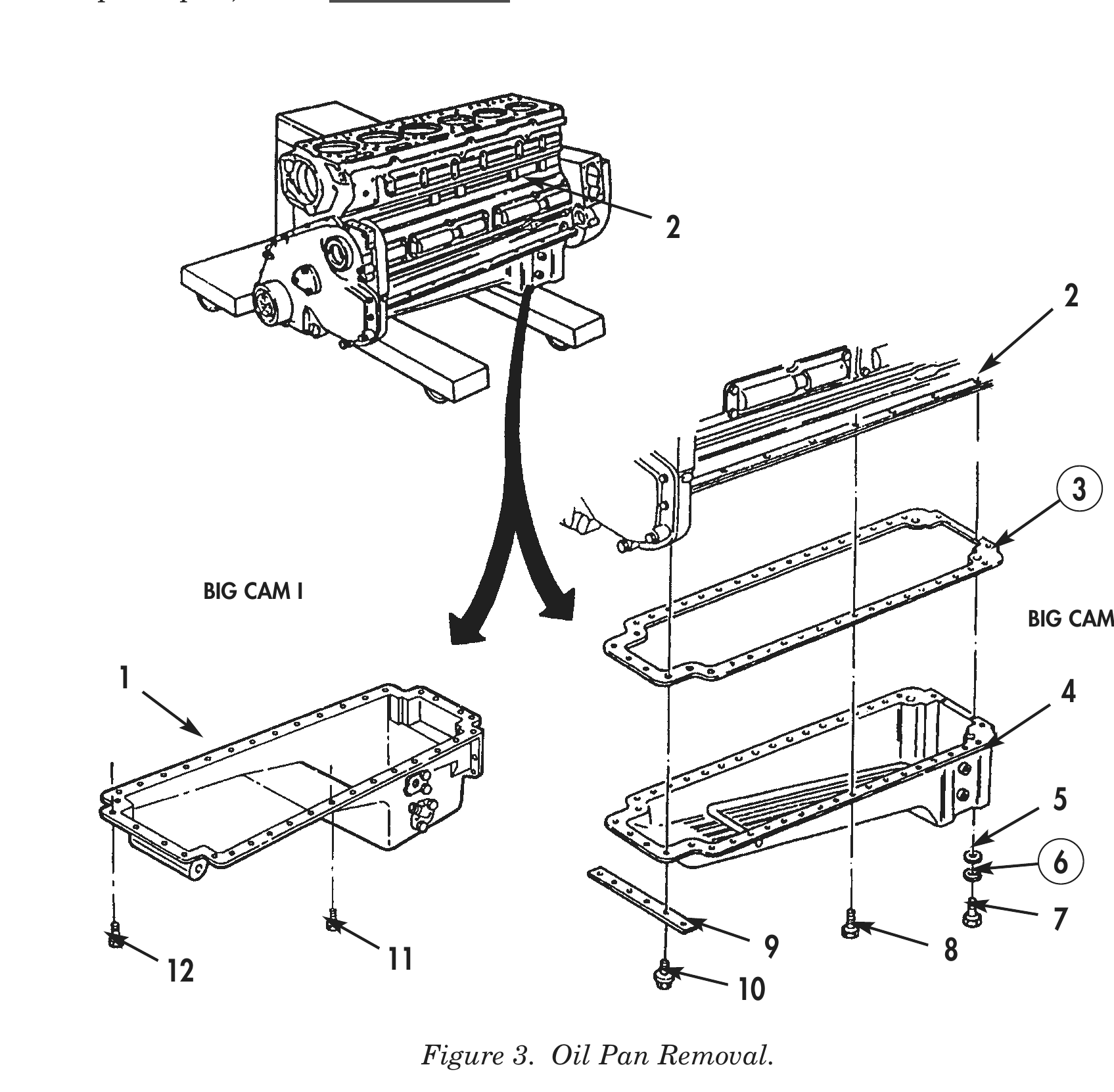
1. Remove four bolts (10) and engine shipping support (9) from oil pan (4).
2. Remove four bolts (7), lockwashers (6), and washers (5) from rear of oil pan (4). Discard lockwashers (6).
3. Remove twenty-eight bolts (8), oil pan (4), and gasket (3) from cylinder block (2). Discard gasket (3).
4. Remove four bolts (12) securing front of oil pan (1) to cylinder block (2).
5. Remove four bolts (7), lockwashers (6), and washers (5) from rear of oil pan (1). Discard lockwashers (6).
6. Remove twenty-eight bolts (11), oil pan (1), and gasket (3) from cylinder block (2). Discard gasket (3).
7. For oil pan repair, refer to WP 0022 00.
BIG CAM I
BIG CAM III
1 4
11 9 8
FRONT GEAR COVER
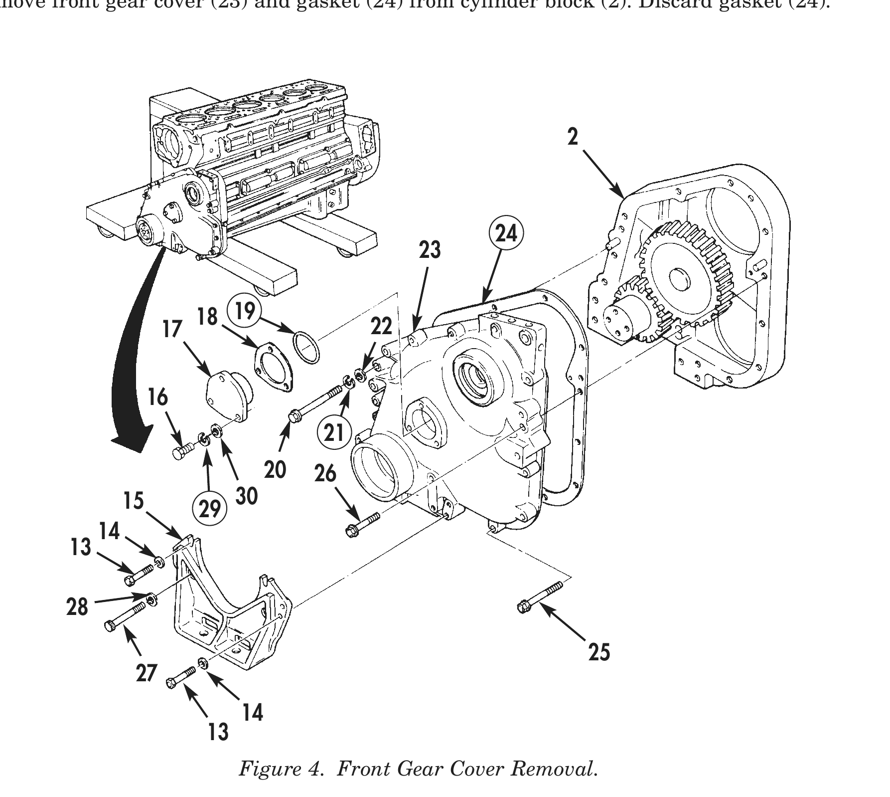
1. Remove six short bolts (13) and washers (14) from front engine support (15).
2. Remove two long bolts (27), washers (28), and front engine support (15) from front gear cover (23).
3. Remove three screws (16), lockwashers (29), washers (30), camshaft support (17), shim pack (18), and O-ring (19) from front gear cover (23). Discard O-ring (19) and lockwashers (29).
4. Remove two screws (20), lockwashers (21), and washers (22) from front gear cover (23). Discard lockwashers (21).
5. Remove three captive washer screws (16), camshaft support (17), shim pack (18), and O-ring (19) from front gear cover (23). Discard O-ring (19).
6. Remove two captive washer screws (20) from front gear cover (23).
7. Remove nine captive washer screws (26) and one captive washer screw (25) from front gear cover (23).
8. Remove front gear cover (23) and gasket (24) from cylinder block (2). Discard gasket (24).
18 19 22
20 26 15 30
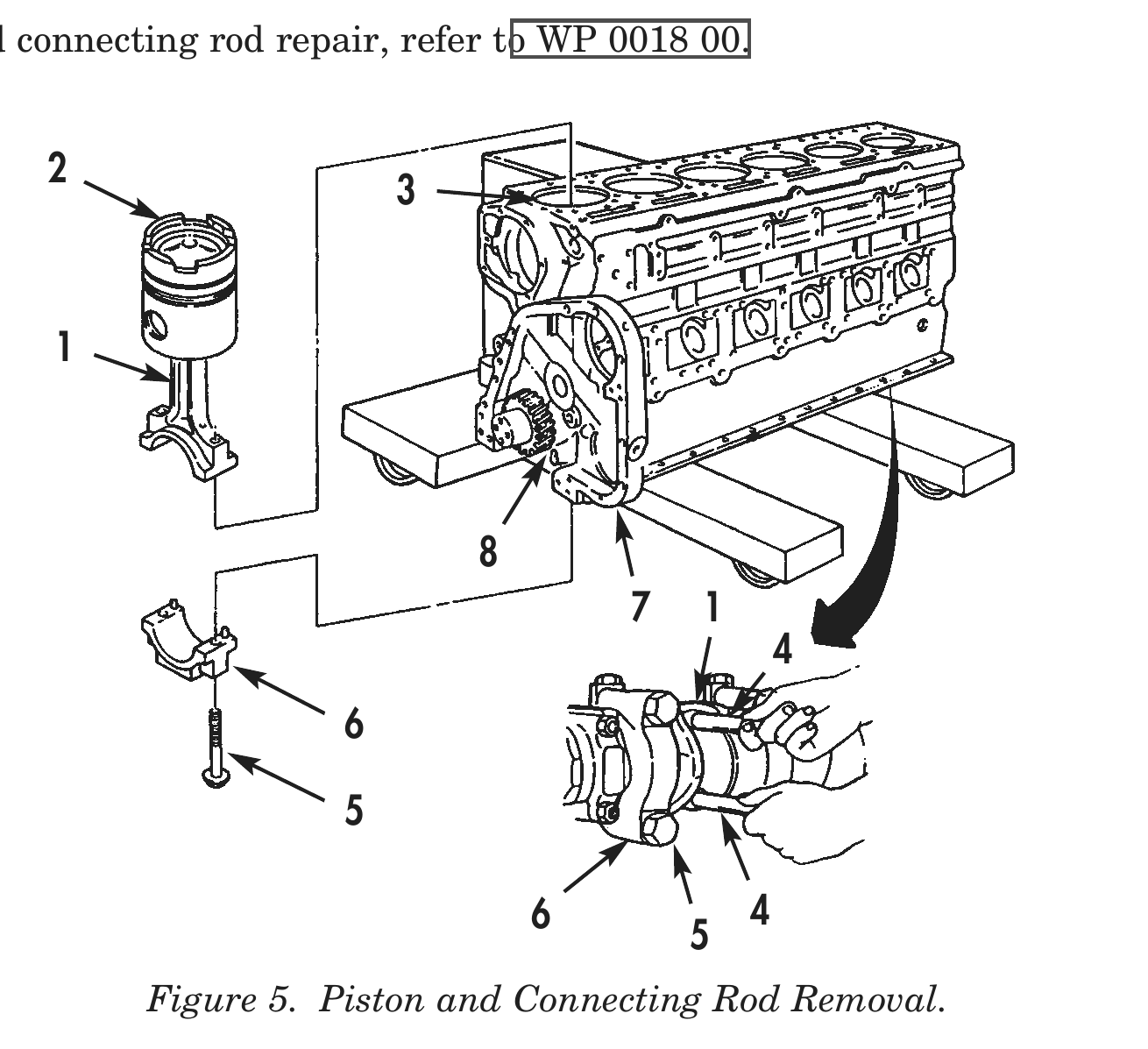
PISTONS AND CONNECTING RODS
1. Place cylinder block (7) in a vertical position with rear of cylinder block (7) facing down.
2. Using a rotary wire brush or aluminum bladed scraper, remove carbon deposits from upper inside of cylinder walls (3).
3. Rotate crankshaft (8) until connecting rod cap (6) is accessible.
4. Loosen two connecting rod bolts (5) until there is approximately 3/8 in. (9.5 mm) clearance between head of bolts (5) and connecting rod cap (6).
5. Using a soft-faced hammer, tap on head of bolts (5) until connecting rod cap (6) and connecting rod (1) are separated.
6. Remove bolts (5) and connecting rod cap (6) from connecting rod (1) and crankshaft (8).
7. Install two nylon guide screws (4) in connecting rod (1).
8. Push piston (2) and connecting rod (1) out of cylinder liner (3).
9. Remove two nylon guide screws (4) from connecting rod (1).
10. Repeat steps 1 through 9 to remove remaining five connecting rod caps (6), connecting rods (1), and pistons (2).
11. For piston and connecting rod repair, refer to WP 0018 00.
7 1
6 4 Figure 5. Piston and Connecting Rod Removal.
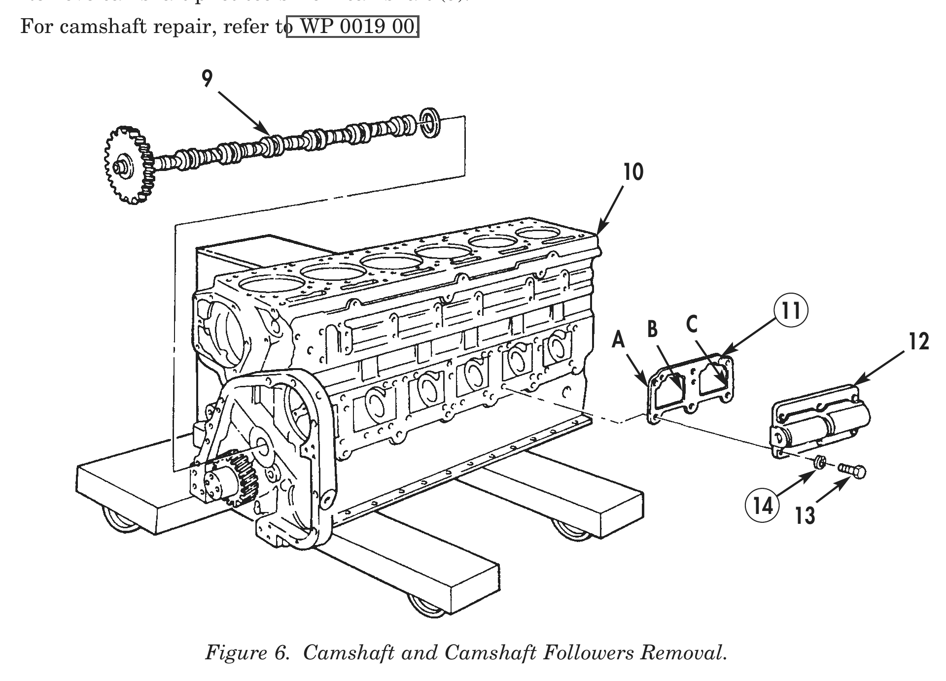
CAMSHAFT FOLLOWERS
1. Remove six screws (13) and lockwashers (14) from cam follower (12). Discard lockwashers (14).
2. Remove cam follower (12), and gasket (11) from cylinder block (10).
3. Using a micrometer, measure gasket (11) at three points (A), (B), and (C) and record average thickness. Discard gasket (11) when all measurements have been taken and recorded.
4. Repeat steps 1 through 3 to remove remaining cam followers (12).
5. Install four camshaft pilot tools on front of camshaft (9).
6. Using camshaft pilot tools, slowly turn camshaft (9) and remove camshaft (9) from cylinder block (10).
7. Remove camshaft pilot tools from camshaft (9).
8. For camshaft repair, refer to WP 0019 00.
C
A B 12
14 13
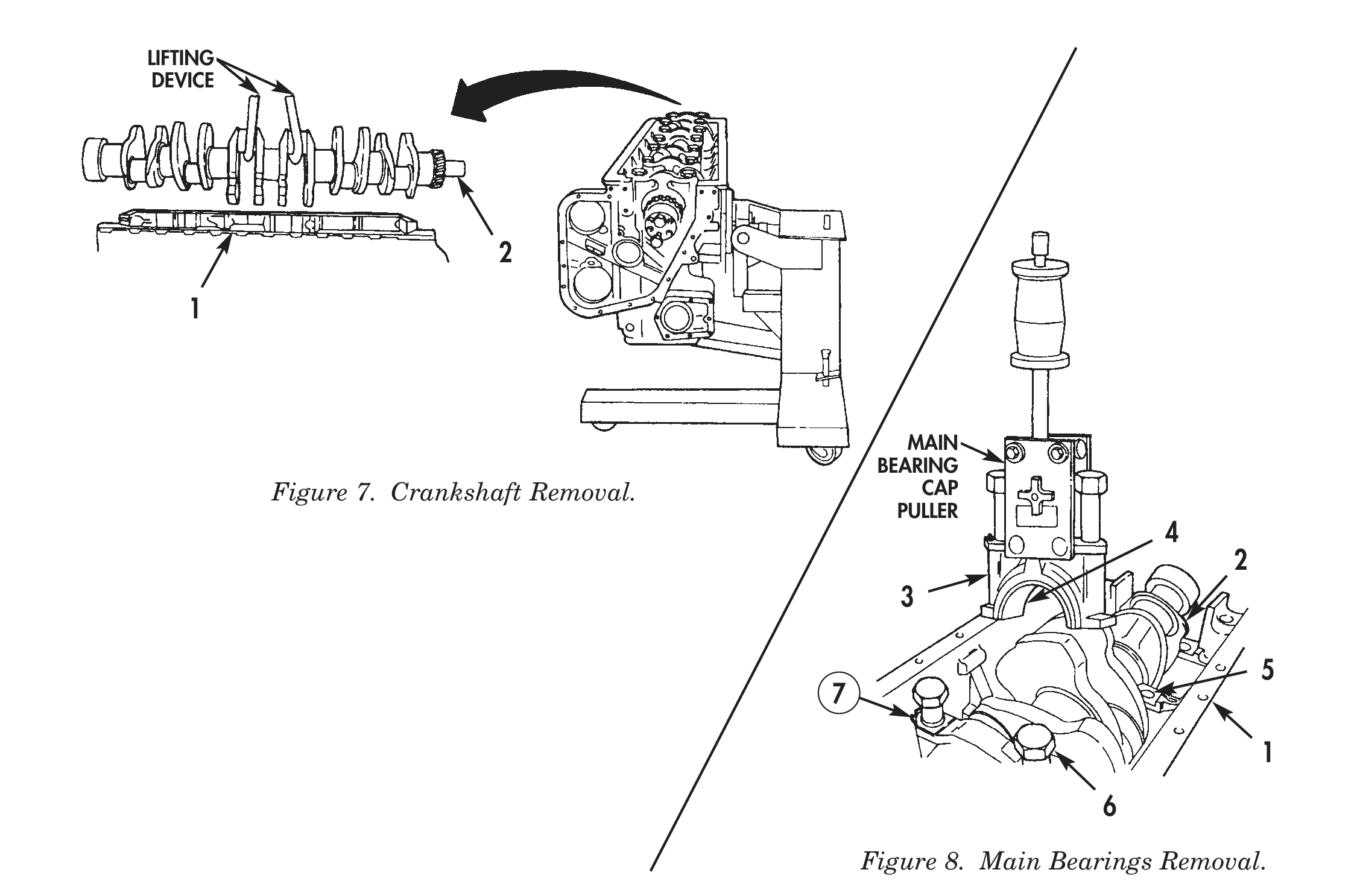
CRANKSHAFT AND MAIN BEARINGS
1. Bend tabs on fourteen locking plates (7) down.
2. Remove fourteen bolts (6) and locking plates (7) from seven main bearing caps (3). Discard locking plates (7).
3. Using main bearing cap puller, remove seven main bearing caps (3), main bearing halves (4), and retaining rings (5) from cylinder block (1).
4. Using lifting device, remove crankshaft (2) from cylinder block (1).
5. For crankshaft repair, refer to WP 0016 00.
6. For cylinder block repair, refer to WP 0013 00.
LIFTING
DEVICE
MAIN
BEARING
PULLER
Figure 8. Main Bearings Removal.
END OF WORK PACKAGE