OIL PAN, DIPSTICK, OIL SUCTION TUBES, AND BREATHER TUBE
TM 9-2815-225-34&P · Work Package 0022 00
DISASSEMBLY, CLEANING AND INSPECTION, ASSEMBLY
INITIAL SETUP
Tools and Special Tools
 General mechanic’s tool kit: automotive
    (Item 1, WP 0061 00)
 Maintenance and repair shop equipment:
    automotive (Item 2, WP 0061 00)
 Automotive maintenance and repair
    supplemental set no. 2 (Item 3, WP 0061 00)

Equipment Condition
 Oil pan, dipstick, oil suction tubes, and
   breather tube removed from engine
   (WP 0012 00).
DISASSEMBLY
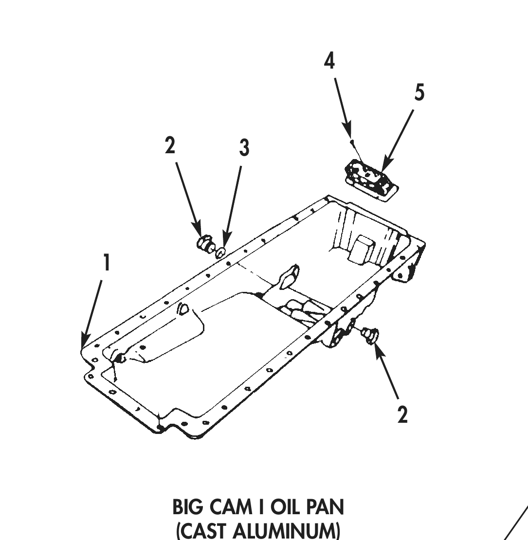
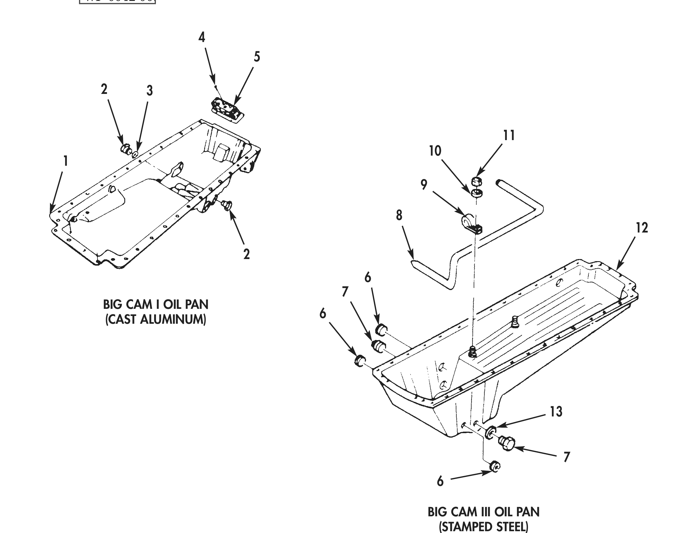
1. Remove two plugs (2) and one spacer (3) from oil pan (1).
2. Remove four screws (4) and strainer element (5) from oil pan (1).
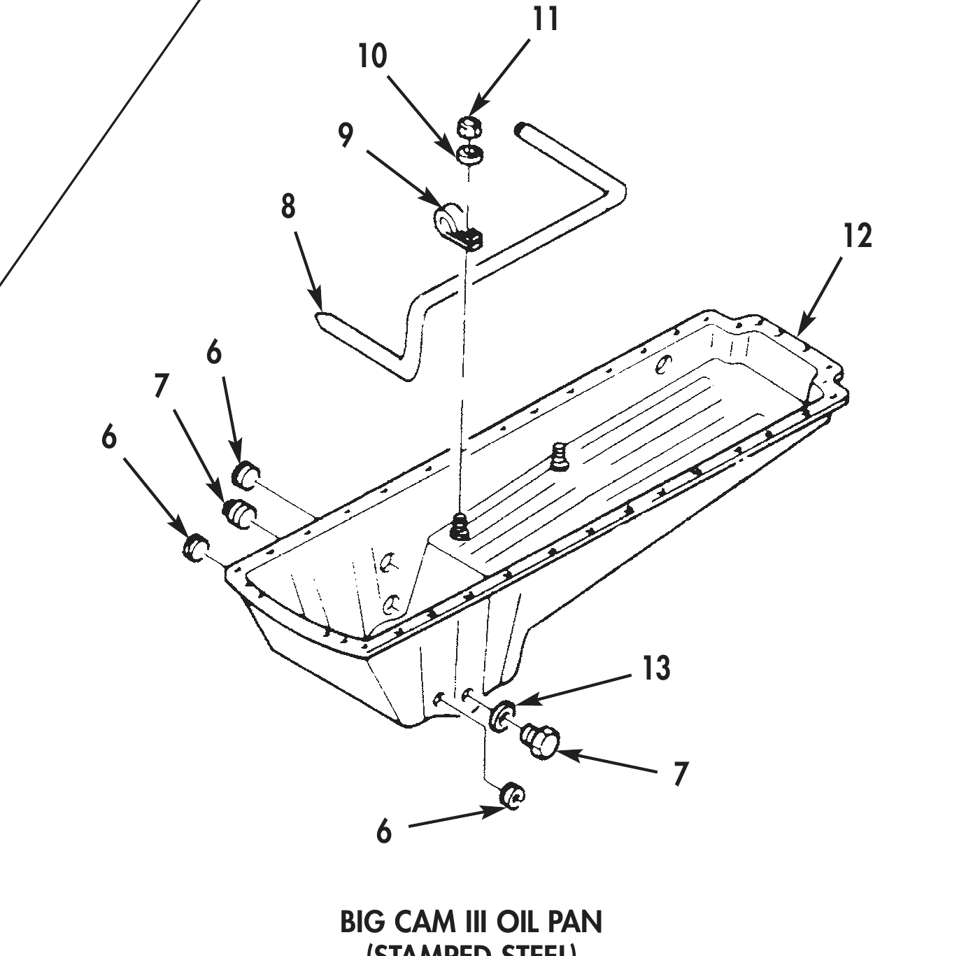
3. Remove washer (10) and nut (11) from oil pan (12).
4. Remove clamp (9) and oil suction tube (8) from oil pan (12).
5. Remove three pipe plugs (6), two plugs (7), and one spacer (13) from oil pan (12).
CLEANING AND INSPECTION
1. For general parts cleaning information, refer to CLEANING, WP 0051 00.
2. For general parts inspection information, refer to INSPECTION, WP 0051 00.
3. Inspect oil pan (12) and (1) for cracks, corrosion, warpage, and stripped or damaged threads. Repair damaged threads as necessary.
4. Inspect plugs (2), (6), and (7) for stripped or damaged threads. Replace any damaged plug.
5. Inspect strainer element (5) for damage. Replace strainer element (5) if damaged.
2 3
BIG CAM I OIL PAN
(CAST ALUMINUM) 11
BIG CAM III OIL PAN
(STAMPED STEEL)
CLEANING AND INSPECTION (Contd)
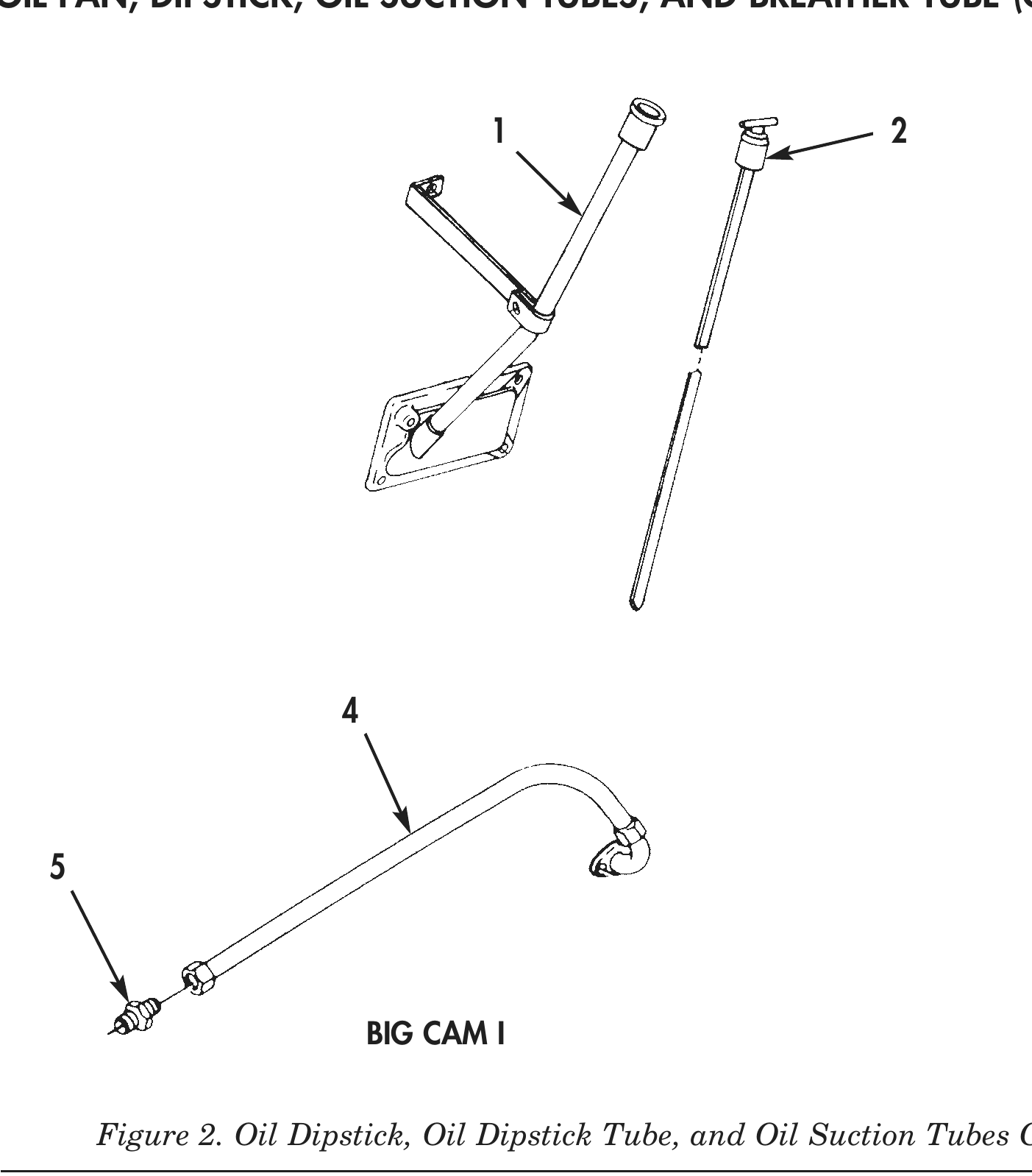
6. Inspect oil level dipstick (2) and oil level dipstick tube (1) for cracks, bends, dents, and corrosion. Discard oil level dipstick (2) or oil level dipstick tube (1) if damaged.
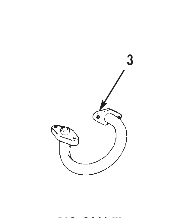
7. Inspect oil suction tube (3) for cracks, bends, dents, corrosion, or rubbing marks caused by vibration. Replace oil suction tube (3) if damaged.
8. Inspect oil suction tube (4) and fitting (5) for cracks, bends, dents, and corrosion. Replace oil suction tube (4) or fitting (5) if damaged.
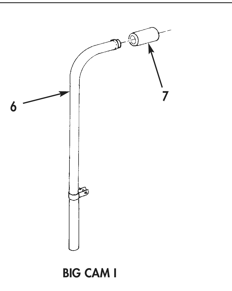
9. Inspect breather tube (6) for cracks, bends, dents, and corrosion. Replace breather tube (6) if damaged.
10. Inspect breather hose (7) for rubbing marks caused by vibration, swelling, or cracks. Replace breather hose (7) if damaged.
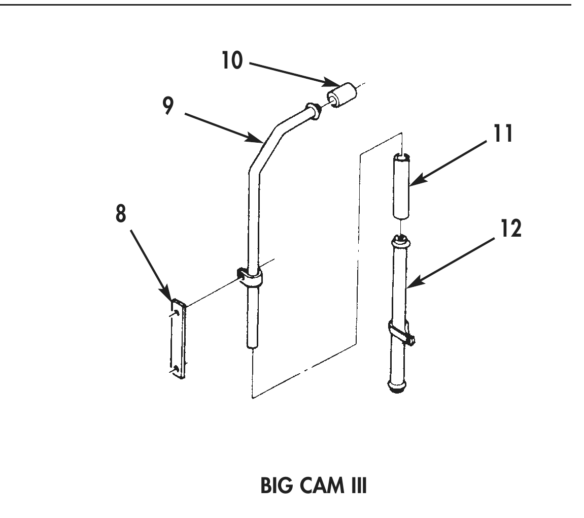
11. Inspect breather tubes (9) and (12) and aftercooler bracket (8) for cracks, bends, dents, and corrosion. Replace breather tube (9) and (12) or bracket (8) if damaged.
12. Inspect breather hoses (10) and (11) for rubbing marks caused by vibration, swelling, or cracks. Discard breather hose (10) or (11) if damaged.
ASSEMBLY
1. Install oil suction tube (8) and clamp (9) on oil pan (12) and secure with washer (10) and nut (11).
2. Install three pipe plugs (6), one spacer (13), and two plugs (7) on oil pan (12).
3. Install one spacer (3) and two plugs (2) in oil pan (1).
4. Install strainer element (5) in oil pan (1) with four screws (4).
5. For oil pans (1) and (12), dipstick, oil suction tubes (8), and breather tube installation, refer to WP 0042 00.
2 3
BIG CAM I OIL PAN
(CAST ALUMINUM) 6
BIG CAM III OIL PAN
(STAMPED STEEL) Figure 4. Oil Pan Assembly.
END OF WORK PACKAGE