FUEL PUMP FRONT COVER AND GOVERNOR
TM 9-2815-225-34&P · Work Package 0038 00
DISASSEMBLY, CLEANING AND INSPECTION, ASSEMBLY
INITIAL SETUP
Tools and Special Tools                             Equipment Condition
 General mechanic’s tool kit: automotive             Fuel pump front cover and governor removed
    (Item 1, WP 0061 00)                               from fuel pump (WP 0033 00).
 Maintenance and repair shop equipment:
    automotive (Item 2, WP 0061 00)
 Automotive maintenance and repair
    supplemental set no. 2 (Item 3, WP 0061 00)
 Press
 Main shaft seal driver (Item 20, WP 0061 00)
 Front cover tachometer seal driver
    (Item 21, WP 0061 00)
 Main shaft gear and bearing installation tool
    (Item 22, WP 0061 00)
 Oil seal assembly tool (Item 23, WP 0061 00)
 Plunger protrusion checking tool
    (Item 24, WP 0061 00)

Material/Parts
 Lubricating oil (Item 19, WP 0060 00)
 Spring (Item 1, Table 21, WP 0062 00)
 Retaining ring (Item 2, Table 21, WP 0062 00)
 Bearing (Item 3, Table 21, WP 0062 00)
 Two shaft seals (Item 4, Table 21, WP 0062 00)
 Seal (Item 5, Table 21, WP 0062 00)
 Bushing (Item 6, Table 21, WP 0062 00)
 Governor bushing
   (Item 7, Table 21, WP 0062 00)
DISASSEMBLY
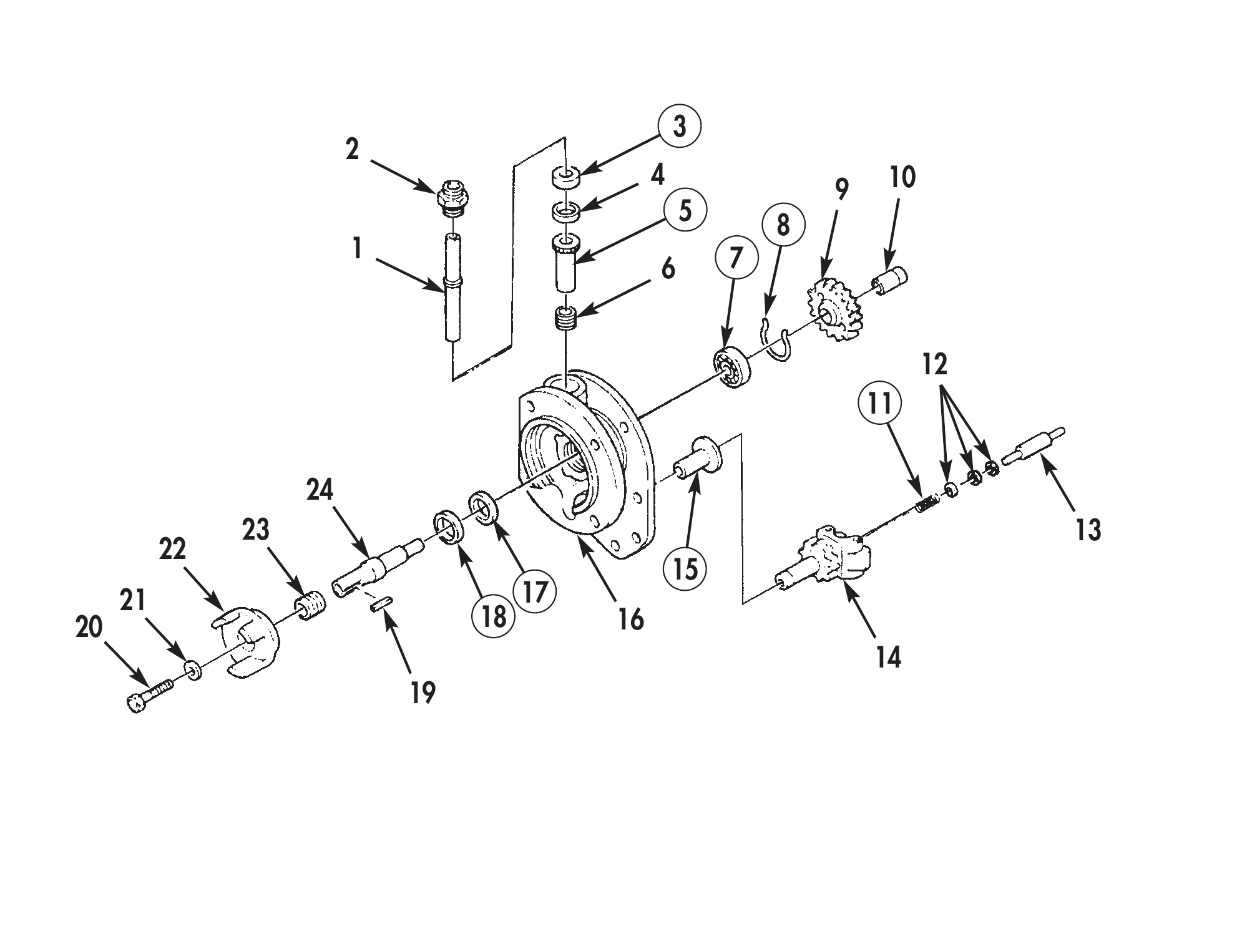
1. Remove weight-assist plunger (13), shims (12), and spring (11) from governor (14). Discard spring (11).
2. Remove screw (20) and washer (21) securing fuel pump drive coupling (22) on fuel pump drive shaft (24).
3. Using puller, remove fuel pump drive coupling (22), tachometer drive gear (23), and coupling key (19) from fuel pump drive shaft (24).
4. Remove retaining ring (8) securing fuel pump drive shaft (24) in fuel pump front cover (16). Discard retaining ring (8).
5. Remove fuel pump drive shaft (24), with bearing (7), fuel pump drive gear (9), and coupling (10) attached, from fuel pump front cover (16).
6. Using press, remove coupling (10) and fuel pump drive gear (9) from fuel pump drive shaft (24).
7. Using press, remove bearing (7) from fuel pump drive shaft (24). Discard bearing (7).
8. Remove tachometer drive housing (2) from fuel pump front cover (16).
9. Using brass punch and hammer, remove tachometer drive shaft (1), with seal (3), spacer (4), bushing (5), and gear (6) attached, from fuel pump front cover (16).
10. Remove gear (6), bushing (5), spacer (4), and seal (3) from tachometer drive shaft (1). Discard seal (3) and bushing (5).
11. Using press, remove two shaft seals (17) and (18) from fuel pump front cover (16). Discard shaft seals (17) and (18).
12. Using brass punch and hammer, remove governor bushing (15) from fuel pump front cover (16). Discard governor bushing (15).
CLEANING AND INSPECTION
1. For general parts cleaning information, refer to CLEANING, WP 0051 00.
2. For general parts inspection information, refer to INSPECTION, WP 0051 00.
3. Inspect weight-assist plunger (13), governor (14), fuel pump drive coupling (22), tachometer drive gear (23), fuel pump drive shaft (24), fuel pump drive gear (9), coupling (10), tachometer drive housing (2), gear (6), tachometer drive shaft (1), and fuel pump front cover (16) for cracks, breaks, excessive wear, and other damage.
4. Inspect fuel pump drive shaft (24) and tachometer drive shaft (1) for scoring, wear, grooves, and other damage.
ASSEMBLY
1. Install new bushing (5) on tachometer drive shaft (1).
2. Using press, install gear (6) on tachometer drive shaft (1) until 0.002–0.005-in. (0.050–0.127-mm) gap between bushing (5) and gear (6) is obtained. Using a feeler gauge, check clearance between gear (6) and bushing (5). Remove and install gear (6) until correct gear (6) to bushing (5) clearance is obtained.
3. Align oil groove in top of bushing (5) with fuel pump drive shaft (1). Using press, install bushing (5) with tachometer drive shaft (1) and gear (6) attached on fuel pump front cover (16) until fully seated.
4. Install spacer (4) on tachometer drive shaft (1) with slotted edge facing down until seated against top of bushing (5).
5. Using front cover tachometer seal driver and hammer, install new seal (3) with spring side down in fuel pump front cover (16).
6. Install tachometer drive housing (2) in fuel pump front cover (16).
7. Lubricate fuel pump drive shaft (24) with clean diesel fuel. Using main shaft gear and bearing installation tool and press, install new bearing (7) on fuel pump drive shaft (24).
8. Using main shaft gear and bearing installation tool and press, install fuel pump drive gear (9) on fuel pump drive shaft (24) until fully seated on bearing (7).
9. Apply lubricating oil to fuel pump drive shaft (24) and bore of coupling (10). Using press, install coupling (10) on fuel pump drive shaft (24) until fully seated against fuel pump drive gear (9).
10. Using main shaft seal driver and press, install first new shaft seal (17) in fuel pump front cover (16) with lip facing back of fuel pump front cover (16).
11. Using main shaft seal driver and press, install second new shaft seal (18) on fuel pump front cover (16) with lip facing front of fuel pump front cover (16).
12. Using oil seal assembly tool and press, install fuel pump drive shaft (24) with bearing (7) and gear (9) attached in fuel pump front cover (16) until bearing (7) is fully seated. Ensure first shaft seal (17) and second shaft seal (18) are not moved during assembly.
13. Install new retaining ring (8) on fuel pump drive shaft (24) between fuel pump drive gear (9) and bearing (7). Look through holes in fuel pump drive gear (9) to ensure retaining ring (8) is properly seated in groove.
14. Install coupling key (19) in fuel pump drive shaft (24).
15. Position tachometer drive gear (23) and fuel pump drive coupling (22) on fuel pump drive shaft (24). Using press, slowly install tachometer drive gear (23) and fuel pump drive coupling (22) on fuel pump drive shaft (24) until fully seated. Ensure tachometer drive gear (23) and tachometer gear teeth are properly aligned.
16. Install screw (20) and washer (21) in fuel pump drive shaft (24). Tighten screw (20) 5 lb-ft (7 N•m).
17. Using press, install new governor bushing (15) in fuel pump front cover (16).
ASSEMBLY (Contd)
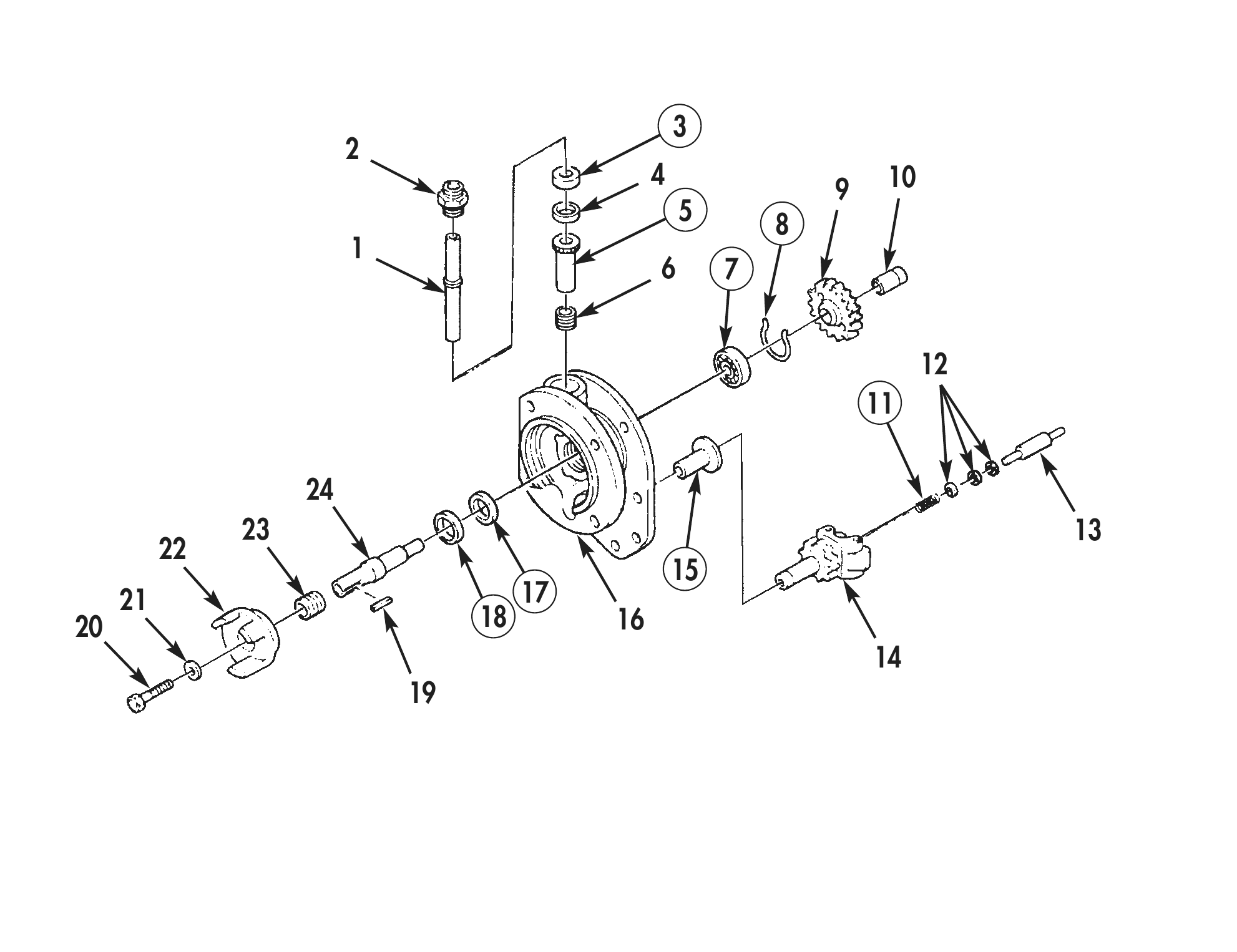
18. Install governor (14) in governor bushing (15) and rotate governor (14) until weights are open.
19. Install weight-assist plunger (13) with small end facing governor weights. Install shims (12) and new spring (11) in bore of governor (14).
20. Using plunger protrusion checking tool and dial indicator, measure protrusion of weight-assist plunger (13). Weight-assist plunger (13) protrusion should be 0.800 in. (20.32 mm). If weight- assist plunger (13) protrusion is less than 0.800 in. (20.32 mm), add shims (12). If weight-assist plunger (13) protrusion is more than 0.800 in. (20.32 mm), remove shims (12) or grind end of weight-assist plunger (13). Repeat procedure until weight-assist plunger (13) protrusion is correct.
21. Install fuel pump front cover and governor (Refer to WP 0040 00).
4 10 5 8 6 7
23 13 21 17 20 18 16
END OF WORK PACKAGE