FUEL GEAR PUMP
TM 9-2815-225-34&P · Work Package 0036 00
DISASSEMBLY, CLEANING AND INSPECTION, ASSEMBLY
INITIAL SETUP
Tools and Special Tools                             Equipment Condition
 General mechanic’s tool kit: automotive             Fuel gear pump removed from fuel pump
    (Item 1, WP 0061 00)                               housing (WP 0033 00).
 Maintenance and repair shop equipment:
    automotive (Item 2, WP 0061 00)
 Automotive maintenance and repair
    supplemental set no. 2 (Item 3, WP 0061 00)
 Pressurizing valve driver
    (Item 38, WP 0061 00)
 Press

Material/Parts
 Lubricating oil (Item 19, WP 0060 00)
 Pipe sealant (Item 25, WP 0060 00)
 Two lockwashers
   (Item 1, Table 19, WP 0062 00)
 Gasket (Item 2, Table 19, WP 0062 00)
 Pressure valve (Item 3, Table 19, WP 0062 00)
 Two bearing sleeves
   (Item 4, Table 19, WP 0062 00)
 Dowel ring (Item 5, Table 19, WP 0062 00)
DISASSEMBLY
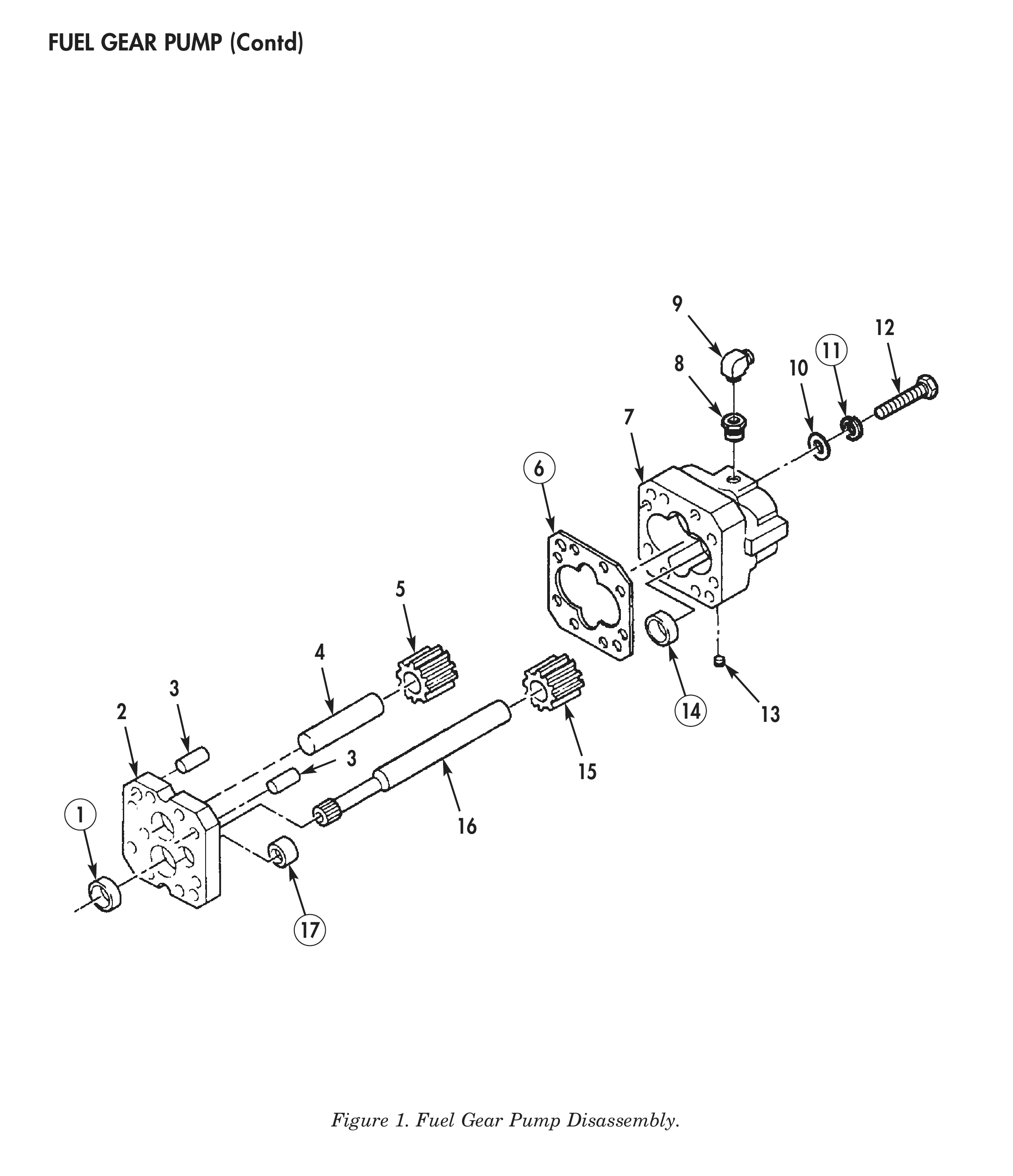
1. Remove fuel supply elbow (9), adapter (8), and pipe plug (13) from gear body (7).
2. Remove two screws (12), lockwashers (11), washers (10), gear cover (2), and gasket (6) from gear body (7). Discard lockwashers (11) and gasket (6).
3. Remove idler shaft (4) and drive shaft (16) from gear body (7).
4. Using press, remove idler gear (5) from idler shaft (4).
5. Using press, remove drive gear (15) from drive shaft (16).
6. Remove two dowel pins (3), dowel ring (1), pressure valve (17), and two bearing sleeves (14) from gear cover (2). Discard pressure valve (17), bearing sleeves (14), and dowel ring (1).
CLEANING AND INSPECTION
1. For general parts cleaning information, refer to CLEANING, WP 0051 00.
2. For general parts inspection information, refer to INSPECTION, WP 0051 00.
3. Inspect fuel supply elbow (7), adapter (6), and pipe plug (8) for cracks, chipped or stripped threads.
4. Inspect idler shaft (3) and drive shaft (10) for scoring, bends, or stripped teeth.
5. Using micrometer or equivalent, measure ends of idler shaft (3) outside diameter at center and end of idler shaft (3). Minimum outside diameter is 0.499 in. (12.70 mm).
6. Using micrometer or equivalent, measure drive shaft (10) outside diameter at end and center of drive shaft (10). Minimum outside diameter is 0.499 in. (12.70 mm).
7. Inspect idler gear (4) and drive gear (9) for chips, cracks, and stripped teeth.
8. Using micrometer or equivalent, measure idler gear (4) and drive gear (9) length. Idler gear (4) and drive gear (9) length should be 0.7483–0.7486 in. (19.007–19.014 mm).
9. Inspect gear body (5) and gear cover (1) for scoring, cracks, or stripped threaded holes.
10. Using depth micrometer, measure gear body (5) depth. Gear body depth should be 0.7478–0.7481 in. (18.994–19.002 mm).
11. Using telescoping gauge and micrometer, measure gear body (5) and gear cover (1) shaft bores inside diameter. Inside diameter should be 0.5011–0.5016 in. (12.728–12.741 mm).
12. Inspect dowel pins (2) for cracks, chips, or bends.
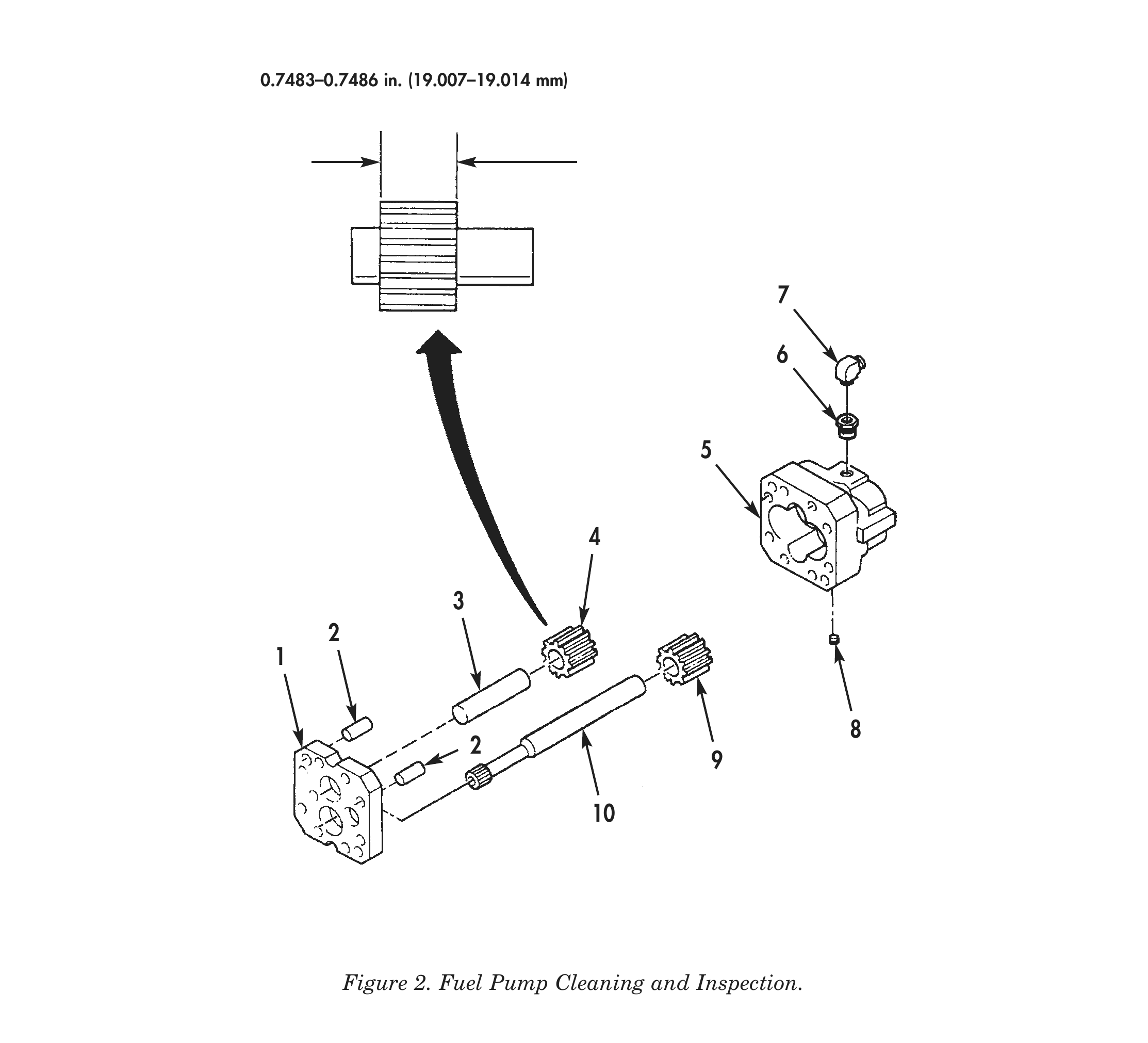
0.7483–0.7486 in. (19.007–19.014 mm)
ASSEMBLY
1. Using press, install two new bearing sleeves (15) in gear body (7).
2. Using press, install two new bearing sleeves (15) and new dowel ring (1) in gear cover (2).
3. Using pressurizing valve driver, install new pressure valve (18) 0.015 in. (0.381 mm) below face of gear cover (2).
4. Install two dowel pins (3) in gear cover (2).
5. Using press, install drive gear (16) on drive shaft (17) 0.680–0.690 in. (17.272–17.526 mm) from end of drive shaft (17).
6. Using press, install idler gear (5) on idler shaft (4) 0.680–0.690 in. (17.272–17.526 mm) from end of idler shaft (4).
7. Install idler shaft (4) with idler gear (5) attached and drive shaft (17) with drive gear (16) attached in gear cover (2).
8. Align notches in gear cover (2) with notches on gear body (7) and install new gasket (6) and gear cover (2) on gear body (7) with two screws (12), new lockwashers (11), and washers (10). Tighten screw (12) 11–13 lb-ft (15–18 N•m).
9. Apply pipe sealant to pipe plug (14) and install in gear body (7). Tighten pipe plug (14) 10–13 lb-ft (14–18 N•m).
10. Install adapter (8) and fuel supply elbow (9) on gear body (7).
11. Using dial indicator, measure drive shaft (17) backlash. Backlash should be 0.001–0.004 in. (0.0254–0.1016 mm). If correct backlash cannot be obtained, disassemble fuel gear pump (13) and replace idler gear (5) and drive shaft gear (16).
12. Using dial indicator, measure drive shaft (17) end play. End play should be between 0.0009–0.0015 in. (0.0228–0.038 mm). If correct end play cannot be obtained, disassemble fuel gear pump (13) and replace gear body (7) and drive shaft (17).
13. Install fuel gear pump (13) on fuel pump housing. Refer to WP 0040 00.
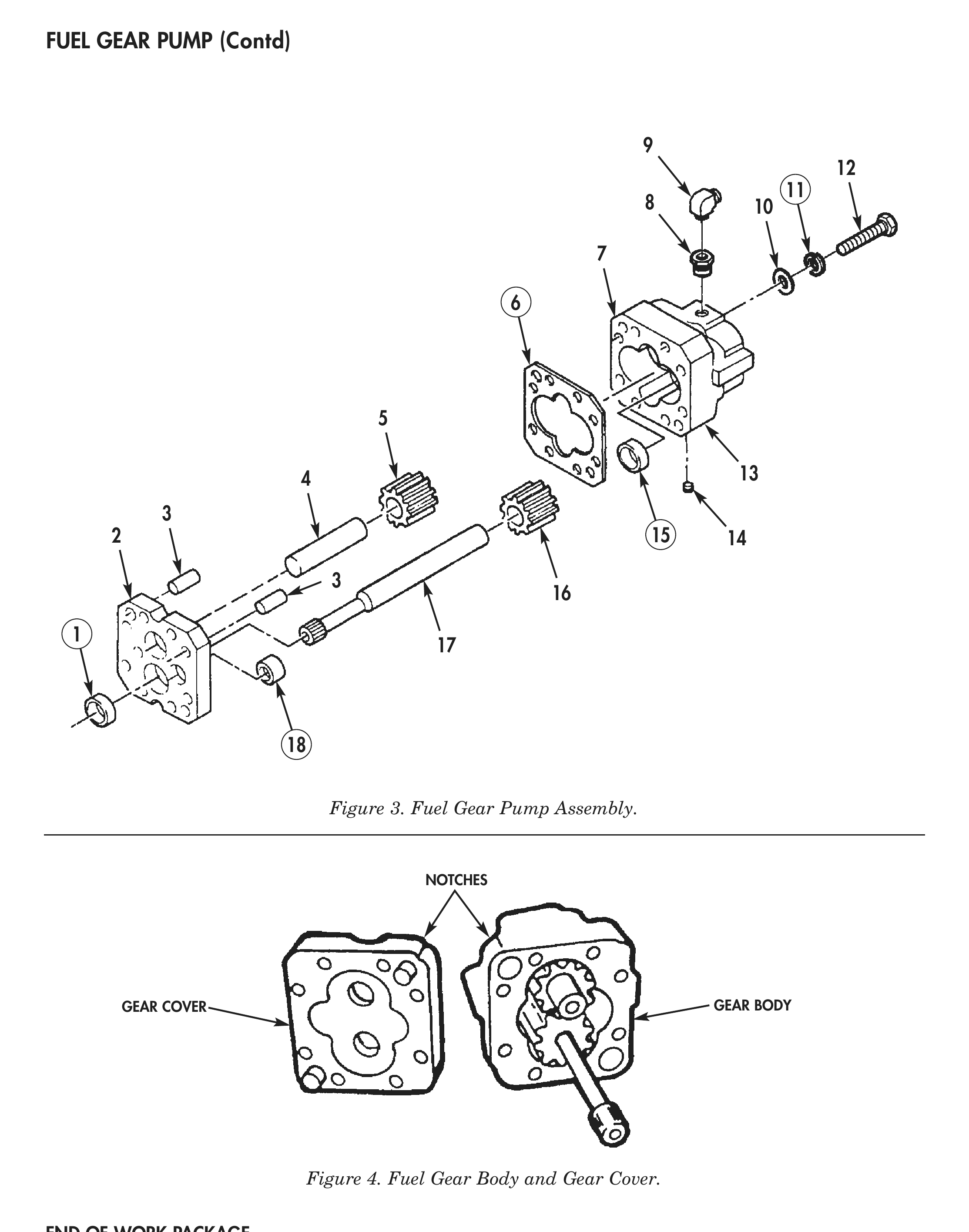
Figure 3. Fuel Gear Pump Assembly.
Figure 4. Fuel Gear Body and Gear Cover.