ENGINE ACCESSORIES REMOVAL
TM 9-2815-225-34&P · Work Package 0010 00
VIBRATION DAMPER AND CRANKSHAFT PULLEY, ACCESSORY DRIVE PULLEY, FUEL PUMP AND
FUEL LINES, AIR COMPRESSOR, ACCESSORY DRIVE HOUSING, OIL PUMP, AIR AFTERCOOLER
INITIAL SETUP
Tools and Special Tools                             Equipment Condition
 General mechanic’s tool kit:                        Engine mounted on maintenance stand
    automotive (Item 1, WP 0061 00)                    (WP 0009 00).
 Maintenance and repair shop equpment:
    automotive (Item 2, WP 0061 00)
 Automotive maintenance and repair
    supplemental set no. 2 (Item 3, WP 0061 00)
 Air compressor wrench
    (Item 18, WP 0061 00)

Materials/Parts
 Cap and plug set (Item 29, WP 0060 00)
VIBRATION DAMPER AND CRANKSHAFT PULLEY
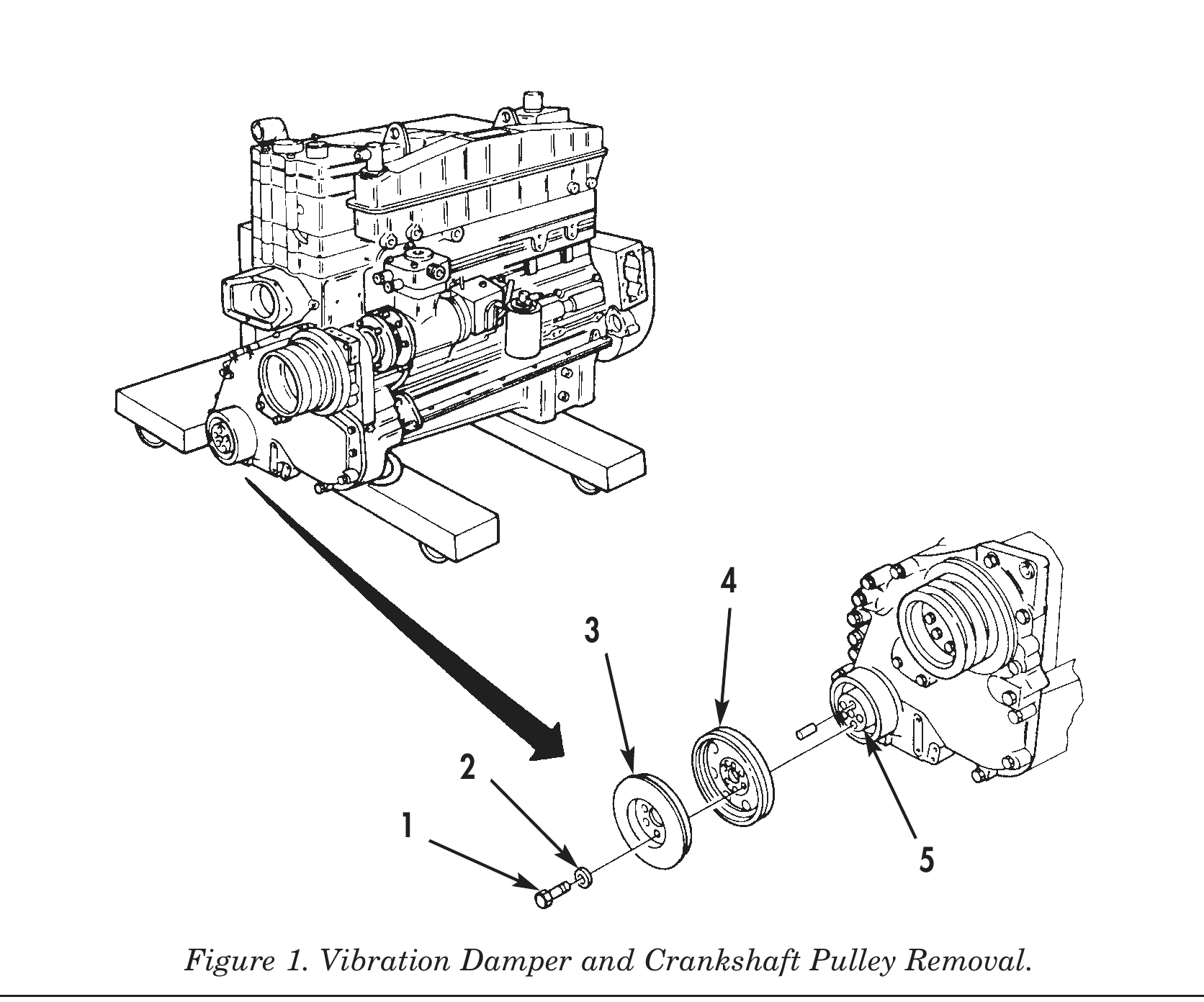
1. Insert prybar in teeth of flyweel and flywheel housing to prevent crankshaft (5) from turning.
2. Remove six screws (1), washers (2), vibration damper (3), and crankshaft pulley (4) from crankshaft (5).
ACCESSORY DRIVE PULLEY
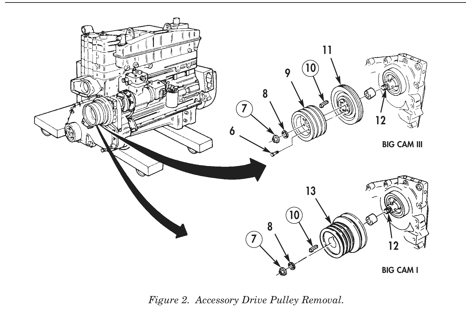
1. Remove six screws (6) and front accessory drive pulley (9) from rear accessory drive pulley (11).
2. Remove locknut (7) and washer (8) retaining rear accessory drive pulley (11) on accessory driveshaft (12). Discard locknut (7).
3. Using puller, remove rear accessory drive pulley (11) from accessory driveshaft (12).
4. Remove keyway seal (10) from accessory driveshaft (12). Discard keyway seal (10).
5. Remove locknut (7) and washer (8) retaining accessory drive pulley (13) on accessory driveshaft (12). Discard locknut (7).
6. Using puller, remove accessory drive pulley (13) from accessory driveshaft (12).
7. Remove keyway seal (10) from accessory driveshaft (13). Discard keyway seal (10).
8. For accessory drive pulley (9) and (13) repair, refer to WP 0029 00.
FUEL PUMP AND FUEL LINES
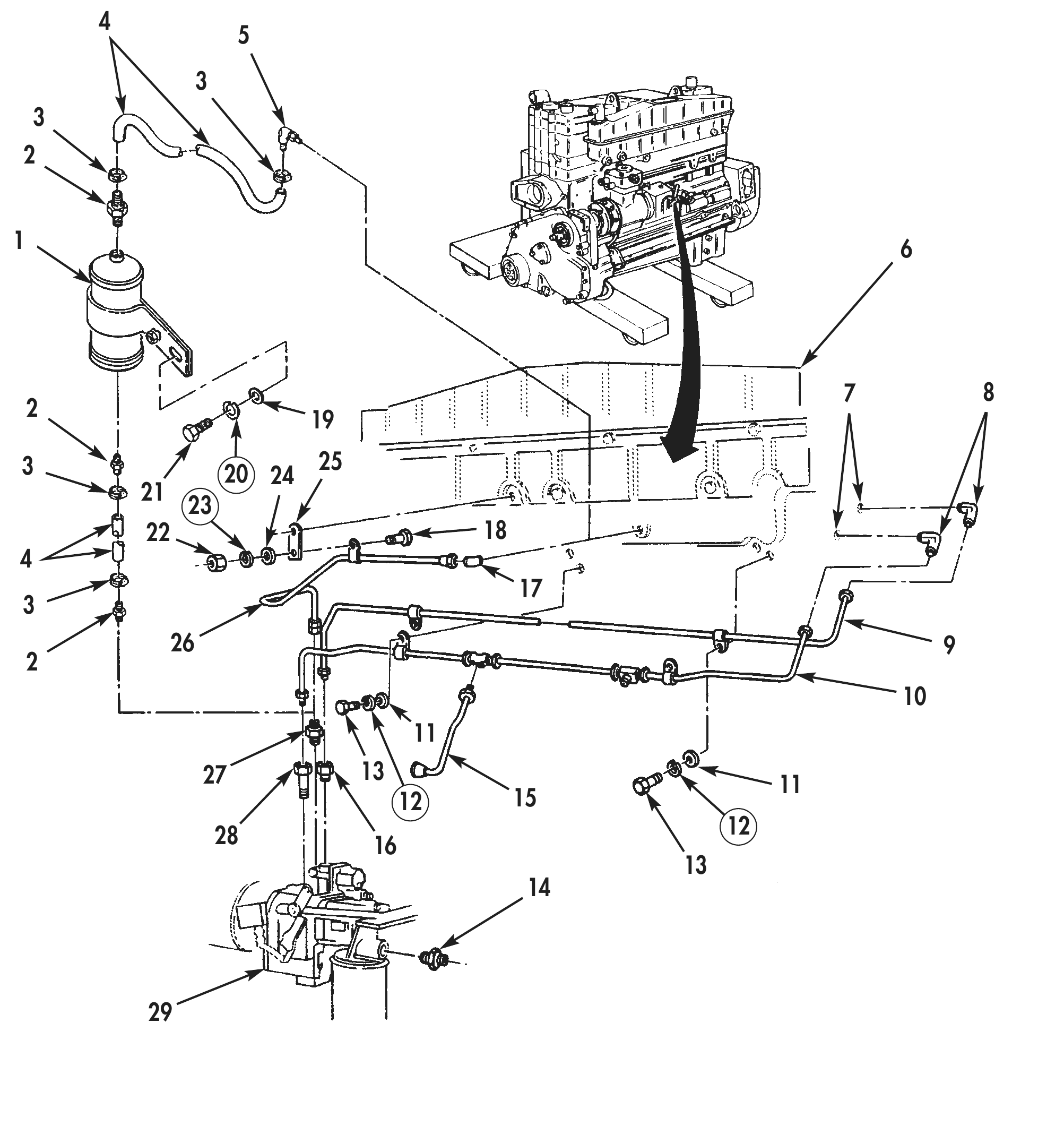
1. Remove four hose clamps (3) and two air supply hoses (4) from ASA air tank (1).
2. Remove air aftercooler elbow (5) from air aftercooler (6).
3. Remove ASA hose fittings (2) from ASA air tank (1).
4. Remove screw (21), lockwasher (20), washer (19), and ASA air tank (1) from air aftercooler (6). Discard lockwasher (20).
5. Remove nut (22), lockwasher (23), washer (24), and screw (18) securing bracket (25) and air supply line (26) to air aftercooler (6). Discard lockwasher (23).
6. Remove adapter (17) from air aftercooler (6).
7. Remove air supply line (26) and valve (27) from fuel pump (29).
8. Remove two screws (13), lockwashers (12), and washers (11) securing fuel supply line (9) and fuel return line (10) to air aftercooler (6). Discard lockwashers (12).
9. Remove fuel return lines (10) and (15) and fuel pump adapter (28) from fuel pump (29).
10. Remove fuel supply line (9) and fuel pump adapter (16) from fuel pump (29).
11. Remove fuel return line (10), fuel supply line (9), and two cylinder head adapters (8) from cylinder head (7).
12. Remove fuel pump adapter (14) from fuel pump (29).
FUEL PUMP AND FUEL LINES (Contd)
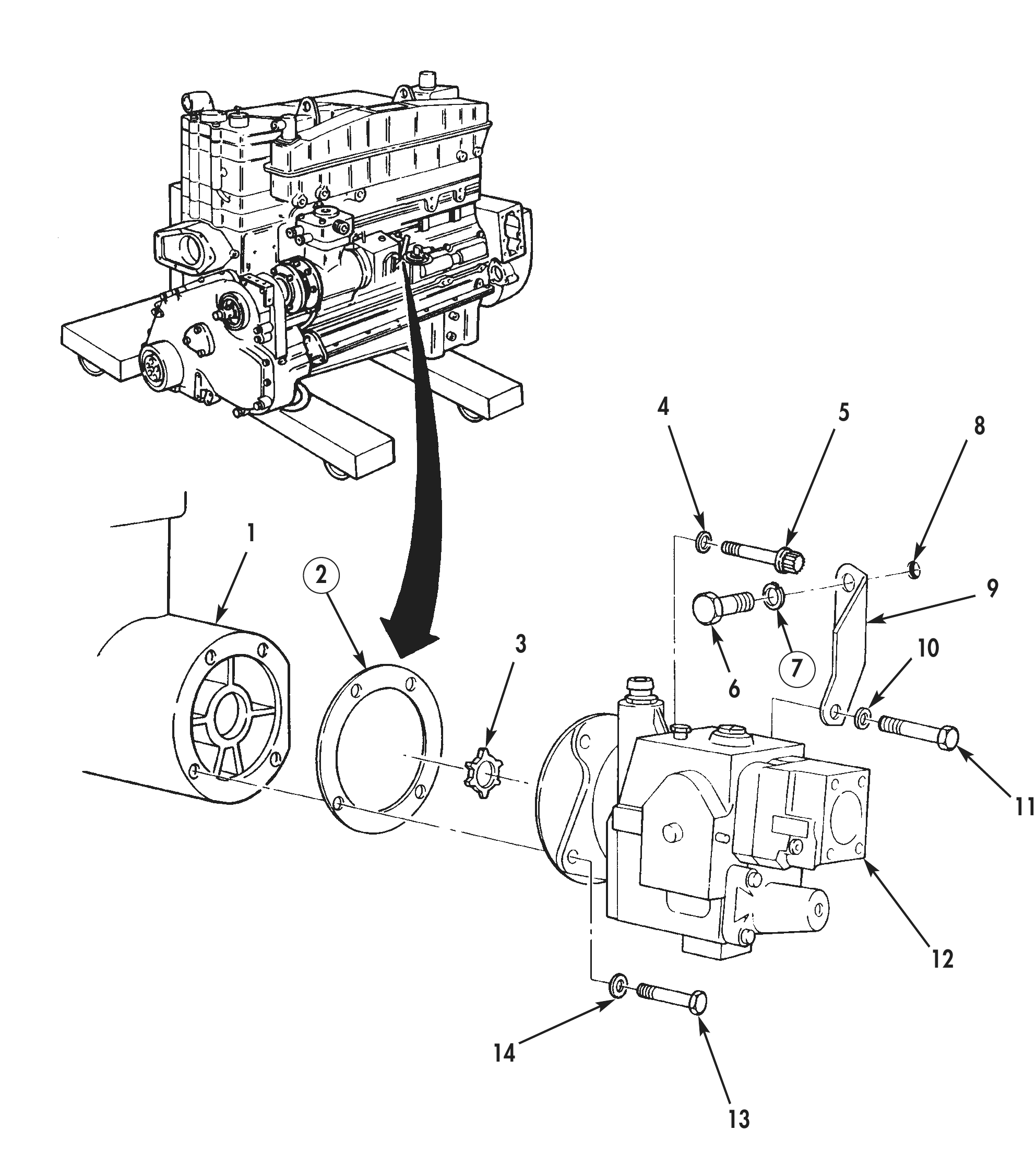
13. Remove bolt (6) and lockwasher (7) securing support bracket (9) to cylinder head (8). Discard lockwasher (7).
14. Using air compressor wrench, remove four bolts (5), washers (4), support bracket (9) securing and fuel pump (12) to air compressor (1).
15. Using air compressor wrench, remove bolt (13) and washer (14) securing fuel pump (12) to air compressor (1).
16. Remove three bolts (11), washers (10), and support bracket (9) securing fuel pump (12) to air compressor (1).
17. Using a soft-sided mallet, tap fuel pump (12) lightly to remove from air compressor (1).
18. Remove gasket (2) and spider coupling (3) from air compressor (1) or fuel pump (12). Discard gasket (2).
19. For fuel pump repair, refer to WP 0033 00.
AIR COMPRESSOR
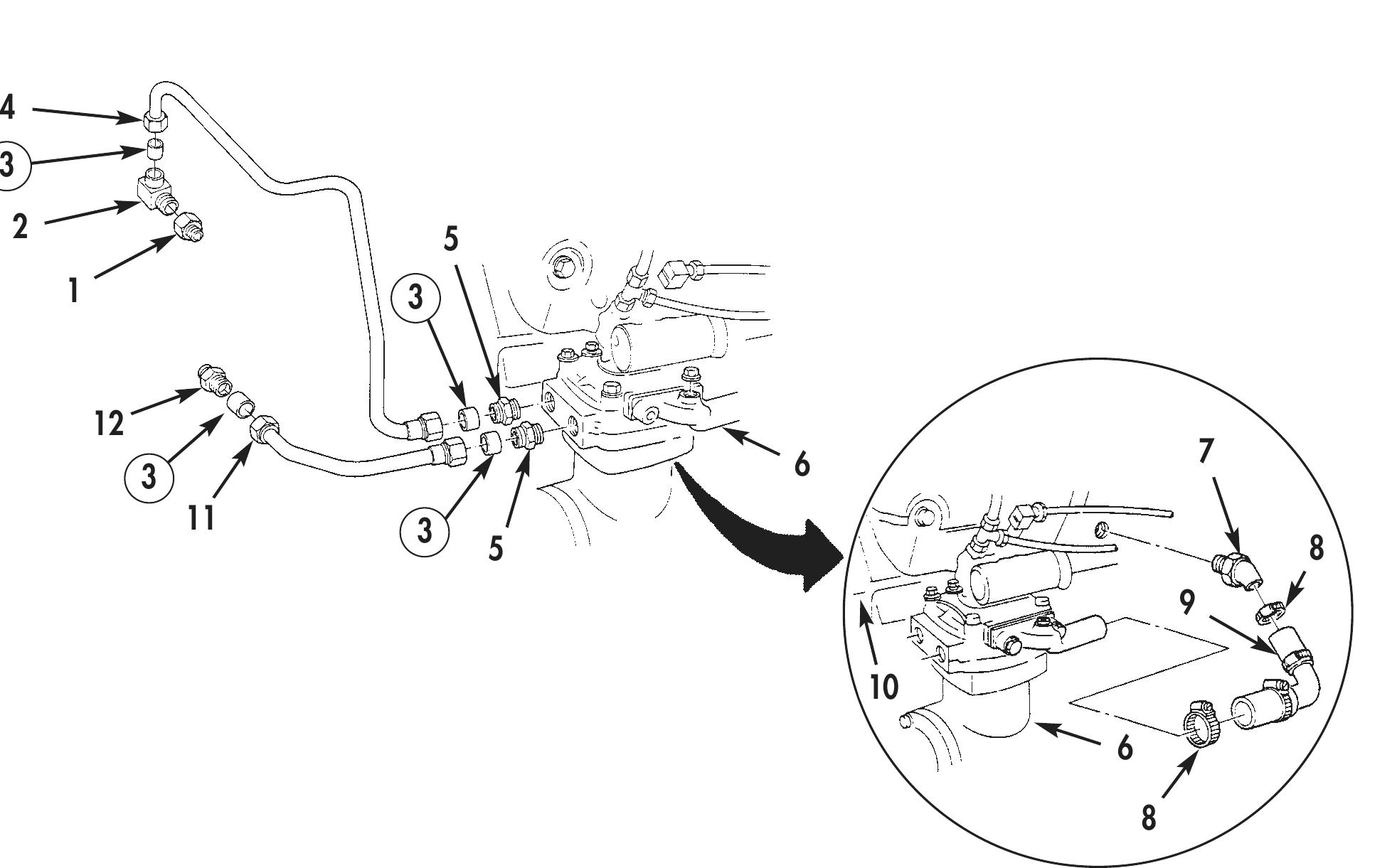
1. Remove coolant inlet tube (11), coolant outlet tube (4), two bushings (3), and elbow (2) from air coolant adapters (1) and (12). Discard bushings (3).
2. Remove coolant inlet tube (11), coolant outlet tube (4), two bushings (3), and two adapters (5) from air compressor (6). Discard bushings (3).
3. Remove two air inlet hose clamps (8) and air inlet hose (9) from air compressor (6) and elbow (7).
4. Remove elbow (7) from cylinder block (10).
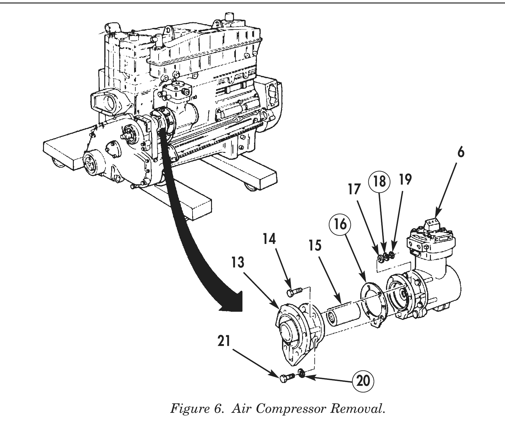
5. Using air compressor wrench, remove two bolts (21) and lockwashers (20) securing air compressor (6) to accessory drive housing (13). Discard lockwashers (20).
6. Remove two nuts (19), lockwashers (18), washers (17), and bolts (14) securing air compressor (6) to accessory drive housing (13). Discard lockwashers (18).
7. Remove air compressor (6) from accessory drive housing (13).
8. Remove gasket (16) and drive coupling (15) from air compressor (6) or accessory drive housing (13). Discard gasket (16).
9. For air compressor repair, refer to WP 0031 00.
ACCESSORY DRIVE HOUSING
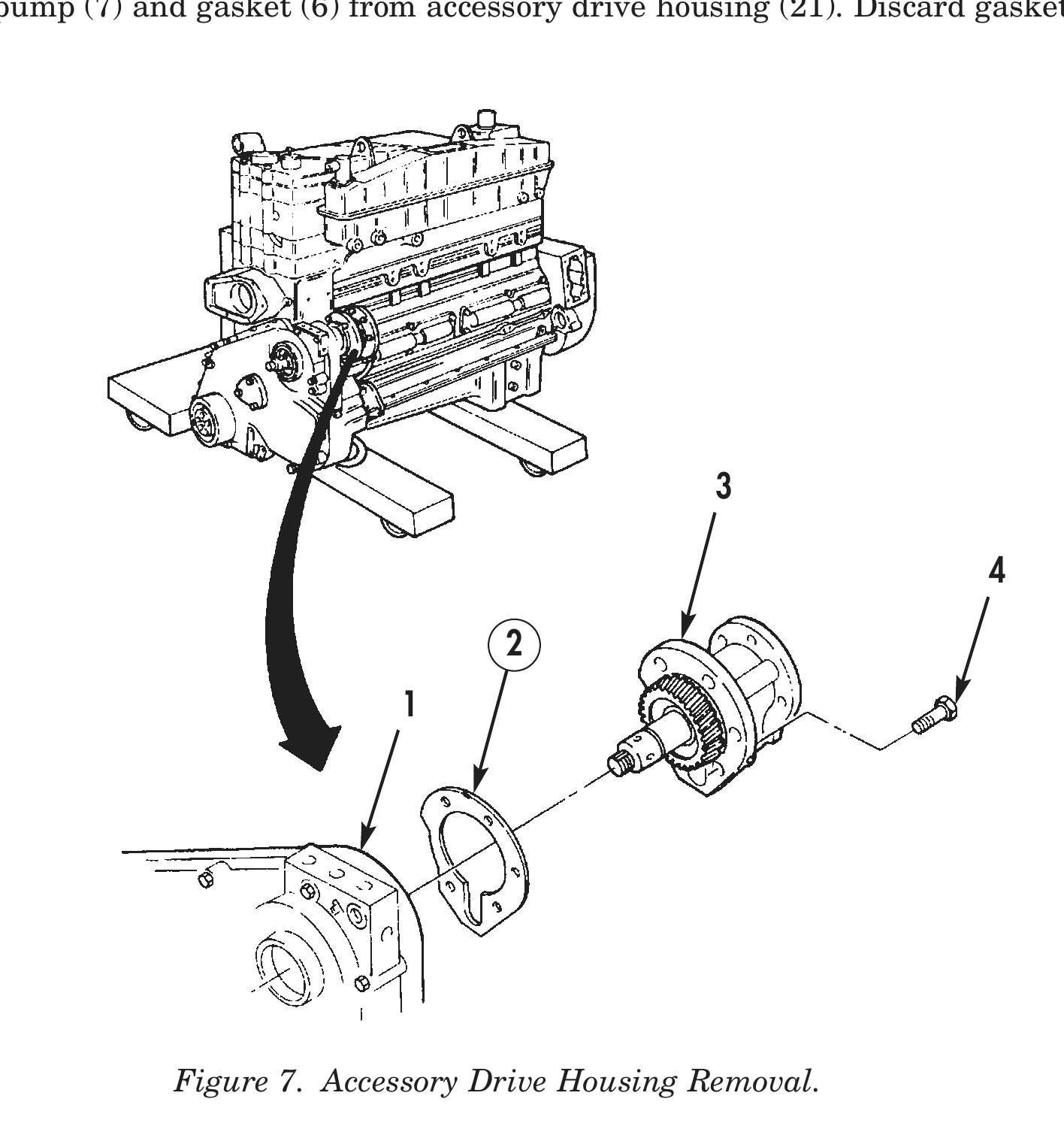
1. Remove five bolts (4), accessory drive housing (3), and gasket (2) from front gear cover (1). Discard gasket (2).
2. For accessory drive housing assembly repair, refer to WP 0029 00.
OIL PUMP
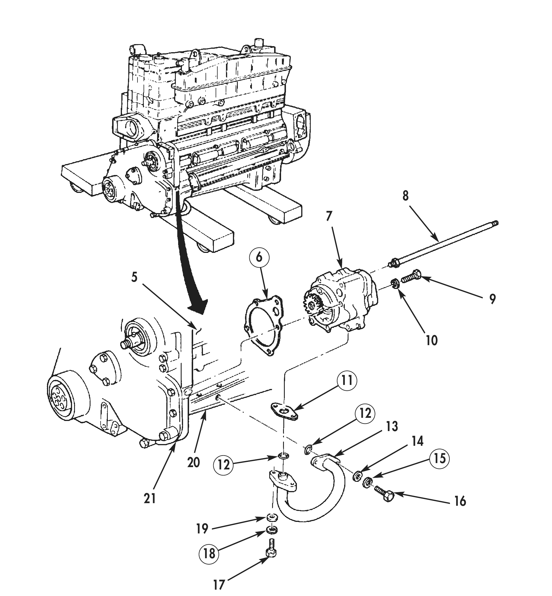
1. Remove two screws (16), lockwashers (15), and washers (14) securing oil suction tube (13) to oil pan (20). Discard lockwashers (15).
2. Remove two screws (17), lockwashers (18), washers (19), and oil suction tube (13) from oil pan (20) and oil pump (7). Discard lockwashers (18).
3. Remove two O-rings (12) and one gasket (11) from oil suction tube (13). Discard O-rings (12) and gasket (11).
4. Remove oil transfer tube (8) from oil pump (7) and cylinder block (5).
5. Remove five bolts (9) and lockwashers (10) securing oil pump (7) to accessory drive housing (21). Discard lockwashers (10).
6. Remove oil pump (7) and gasket (6) from accessory drive housing (21). Discard gasket (6).
OIL PUMP (Contd)
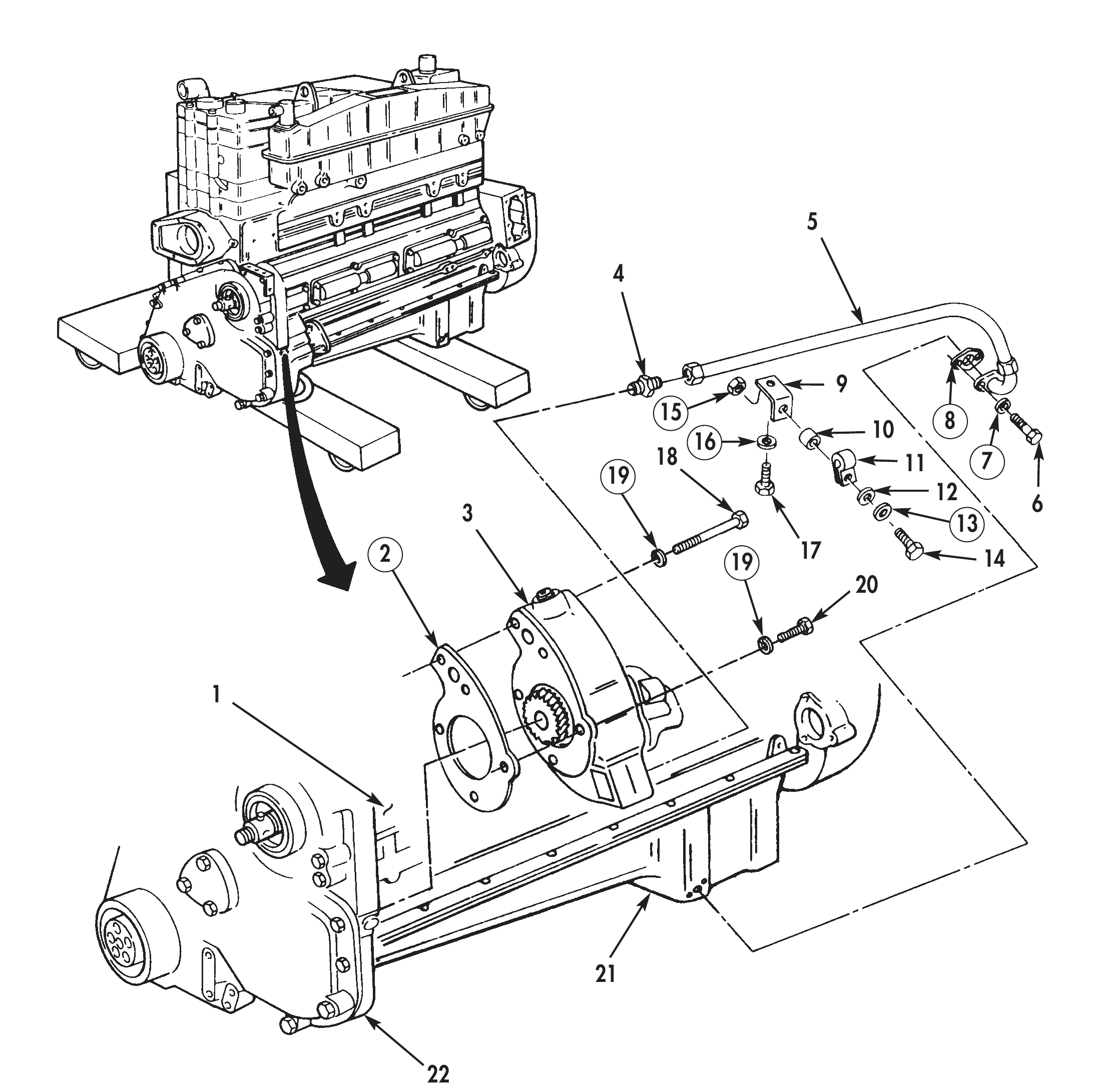
7. Remove bolt (14), lockwasher (13), washer (12), clamp (11), spacer (10), and locknut (15) securing oil suction hose (5) to bracket (9). Discard lockwasher (13) and locknut (15).
8. Remove bolt (17), lockwasher (16), and bracket (9) from oil pan (21) and cylinder block (1). Discard lockwasher (16).
9. Remove two screws (6), lockwashers (7), oil suction hose (5), and gasket (8) from oil pan (21). Discard lockwashers (7) and gasket (8).
10. Remove oil suction hose (5) and adapter (4) from cylinder block (1).
11. Remove three long bolts (18), two short bolts (20), and five lockwashers (19) securing oil pump (3) to accessory drive housing (22). Discard lockwashers (19).
12. Remove oil pump (3) and gasket (2) from accessory drive housing (22). Discard gasket (2).
13. For oil pump repair, refer to WP 0023 00.
AIR AFTERCOOLER
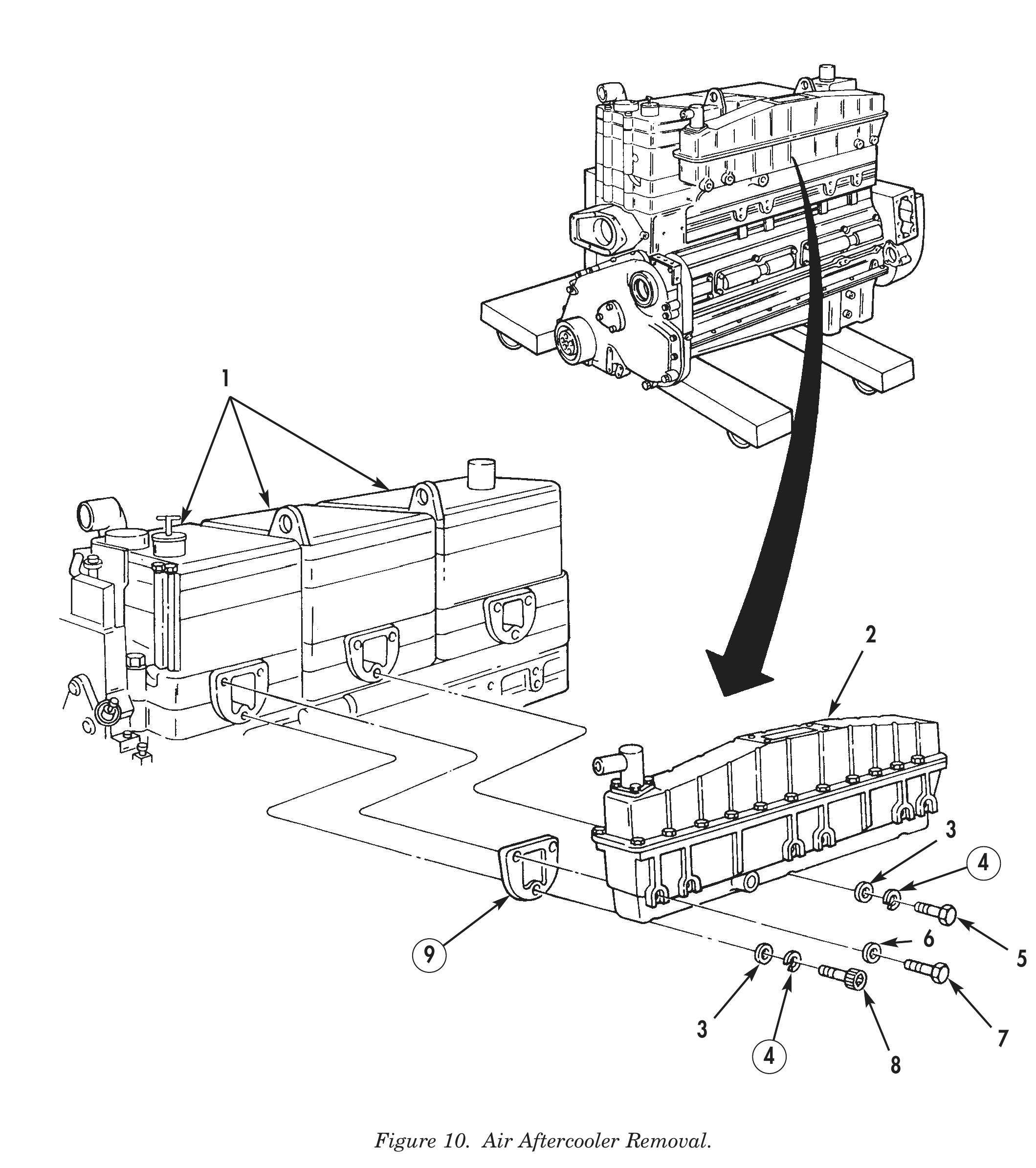
1. Remove three bolts (5), lockwashers (4), and washers (3) securing air aftercooler (2) to cylinder heads (1). Discard lockwashers (4).
2. Remove six bolts (7) and washers (6) securing air aftercooler (2) to cylinder heads (1).
3. Remove screw (8), lockwasher (4), and washer (3) securing air aftercooler (2) to cylinder heads (1). Discard lockwasher (4).
4. Remove two screws (5), lockwashers (4), and washers (3) securing air aftercooler (2) to cylinder heads (1). Discard lockwashers (4).
5. Remove six screws (7) and washers (6) securing air aftercooler (2) to cylinder heads (1).
6. Remove air aftercooler (2) and three gaskets (9) from cylinder heads (1). Discard gaskets (9).
7. For air aftercooler repair, refer to WP 0024 00.