OIL PUMP
TM 9-2815-225-34&P · Work Package 0023 00
DISASSEMBLY, CLEANING AND INSPECTION, ASSEMBLY
INITIAL SETUP
Tools and Special Tools                             Materials/Parts (Contd)
 General mechanic’s tool kit: automotive             Three lockwashers
    (Item 1, WP 0061 00)                               (Item 10, Table 7, WP 0062 00)
 Maintenance and repair shop equipment:              Lockplate (Item 11, Table 7, WP 0062 00)
    automotive (Item 2, WP 0061 00)
 Automotive maintenance and repair                  Equipment Condition
    supplemental set no. 2 (Item 3, WP 0061 00)      Oil pump removed from engine (WP 0010 00).
 Gear puller (Item 40, WP 0061 00)
 Press
 Mandrel (Item 39, WP 0061 00)
 Drill press

Materials/Parts
 OE/HDO 10 lubricating oil
   (Item 19, WP 0060 00)
 Pipe sealant (Item 25, WP 0060 00)
 Gasket (Item 1, Table 7, WP 0062 00)
 Gasket (Item 2, Table 7, WP 0062 00)
 Bushing (Item 3, Table 7, WP 0062 00)
 Two bushings (Item 4, Table 7, WP 0062 00)
 Two O-rings (Item 5, Table 7, WP 0062 00)
 Pressure regulator spring
   (Item 6, Table 7, WP 0062 00)
 Pressure regulator spring
   (Item 7, Table 7, WP 0062 00)
 Bushing (Item 8, Table 7, WP 0062 00)
 Bypass valve spring
   (Item 8, Table 7, WP 0062 00)
 Two bushings (Item 9, Table 7, WP 0062 00)
BIG CAM I
Disassembly
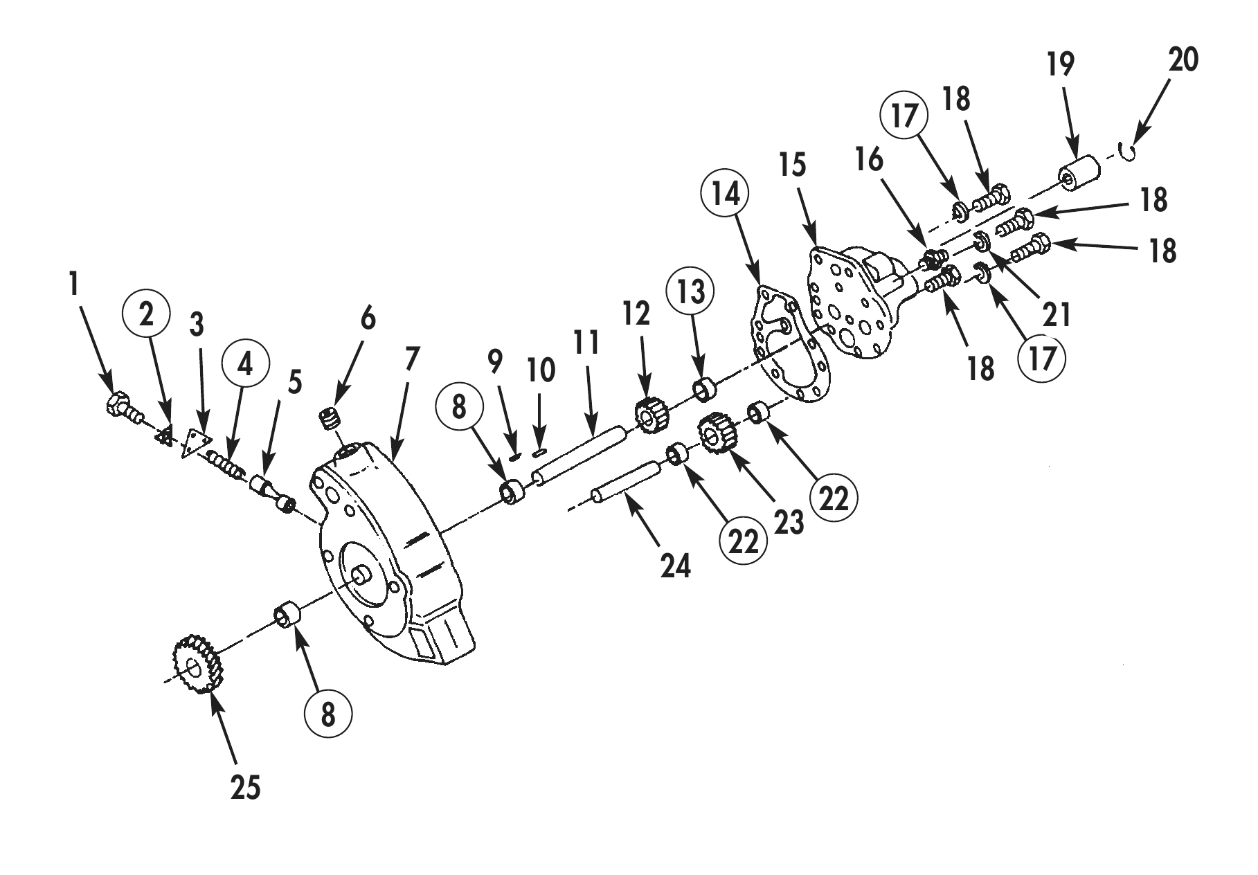
1. Using gear puller, remove oil pump drive gear (25) from oil pump driveshaft (11).
2. Remove woodruff key (9) from oil pump driveshaft (11).
3. Remove snapring (20) and coupling (19) from oil pump driveshaft (11).
4. Remove connector (16) from oil pump housing (15).
5. Remove pipe plug (6) from oil pump body (7).
6. Remove screw (1), lockplate (2), retaining yoke (3), pressure regulator spring (4), and plunger (5) from oil pump body (7). Discard lockplate (2) and pressure regulator spring (4).
7. Remove six screws (18), three lockwashers (17), and two washers (21) securing oil pump housing (15) to oil pump body (7). Discard lockwashers (17).
8. Remove oil pump housing (15) and gasket (14) from oil pump body (7). Discard gasket (14).
9. Remove dowel pin (10) from oil pump body (7).
10. Using press, remove oil pump driveshaft (11), with oil pumping gear (12) attached, from oil pump body (7).
11. Using press, remove oil pump driveshaft (11) from oil pumping gear (12).
12. Remove idler gear (23) from idler shaft (24).
13. Using press, remove idler shaft (24) from oil pump body (7).
14. Using press and mandrel, remove bushing (13) from oil pump housing (15). Discard bushing (13).
15. Using press and mandrel, remove two bushings (8) from oil pump body (7). Discard bushings (8).
16. Using press and mandrel, remove bushings (22) from idler gear (23). Discard bushing (24).
Cleaning and Inspection
1. For general parts cleaning information, refer to CLEANING, WP 0051 00.
2. For general parts inspection information, refer to INSPECTION, WP 0051 00.
3. Inspect oil pumping gear (12) and idler gear (23) for cracks and stripped or chipped teeth.
4. Inspect oil pump body (7) and oil pump housing (15), for cracks and stripped or elongated threaded bolt holes. Repair all stripped or elongated threaded bolt holes.
BIG CAM I (Contd)
Cleaning and Inspection (Contd)
5. Inspect dowel pin (10) for cracks or distortion.
6. Inspect coupling (19) for cracks or stripped teeth.
7. Inspect oil pump driveshaft (11) and idler shaft (24) for galling, breaks, cracks, or bends.
8. Using micrometer or equivalent, measure oil pump driveshaft (11) and idler shaft (25) outside diameter. Minimum outside diameter is 0.874 in. (22.20 mm).
9. Inspect woodruff key (9) for damage and woodruff key slot on oil pump driveshaft (11). Replace woodruff key (9) and oil pump driveshaft (11) if woodruff key (9) fits loose in slot.
10. Inspect pressure regulator plunger (5) for movement in bore of oil pump body (7). Replace pressure regulator plunger (5) if it sticks, binds, or is excessively loose.
19 20 15 16 14 18 1 13
2   3                6                       12                                       21
                                        11
        4                7       9 10                                             18 17
BIG CAM I (Contd)
Assembly
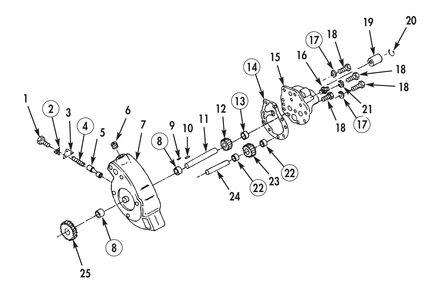
1. Using press and mandrel, install new bushing (22) in idler gear (23). Do not press bushing (22) more than 0.020 in. (0.508 mm) below top surface of idler gear (23). Using drill press and reamer, line-ream inside diameter of bushing (22) to 0.8767–0.8777 in. (22.268–22.293 mm).
2. Using press and mandrel, install two new bushings (8) in oil pump body (7). Do not press bushings (8) more than 0.020 in. (0.508 mm) below top surfaces of oil pump body (7). Using drill press and reamer, line-ream inside diameter of bushings (8) to 0.8767–0.8777 in. (22.268–22.293 mm).
3. Using press and mandrel, install new bushing (13) in oil pump housing (15). Do not press bushing (13) more than 0.020 in. (0.508 mm) below top surfaces of oil pump housing (15). Using drill press and reamer, line-ream inside diameter of bushing (13) to 0.8767–0.8777 in. (22.268–22.293 mm).
4. Using press, install oil pumping gear (12) on oil pump driveshaft (11).
5. Using press, install oil pump driveshaft (11), with oil pumping gear (12) attached, in oil pump body (7) until oil pump driveshaft (11) protrudes 1.035–1.055 in. (26.29–26.80 mm) above oil pump body (7).
6. Using press, install idler shaft (24), with large end facing up, in oil pump body (7) until large end protrudes 0.9375–1.0 in. (23.81–25.40 mm) above oil pump body (7).
7. Install idler gear (23) on idler shaft (24).
8. Using feeler gauge, check clearance from oil pumping gear (12) to oil pump body (7). Clearance should be 0.060–0.070 in. (1.52–1.78 mm). Remove and install oil pumping gear (12) until correct clearance is obtained.
9. Install dowel pin (10) in oil pump body (7).
10. Install new gasket (14) and oil pump housing (15) on oil pump body (7) with two washers (21), three new lockwashers (17), and six screws (18). Tighten screws (18) 35 lb-ft (48 N•m).
11. Install plunger (5), new pressure regulator spring (4), retaining yoke (3), new lockplate (2), and screw (1), in oil pump body (7). Tighten screw (1) 35 lb-ft (48 N•m).
12. Using pipe sealant, install pipe plug (6) in oil pump body (7). Tighten plug (6) 30 lb-ft (41 N•m).
13. Install connector (16) on oil pump housing (15).
BIG CAM I (Contd)
Assembly (Contd)
14. Install coupling (19) and snapring (20) on oil pump driveshaft (11).
15. Install woodruff key (9) in oil pump driveshaft (11).
16. Using press, install oil pump drive gear (25) on oil pump driveshaft (11).
17. Using a dial indicator, check oil pump driveshaft (11) end play. End play should be 0.002–0.008 in. (0.05–0.20 mm).
18. For oil pump installation, refer to WP 0042 00.
19 20 15 16 14 18 1 13
2    3                6                       12                                       21
                                         11
         4                7       9 10                                             18 17
BIG CAM III
Disassembly
1. For oil pump removal, refer to WP 0010 00.
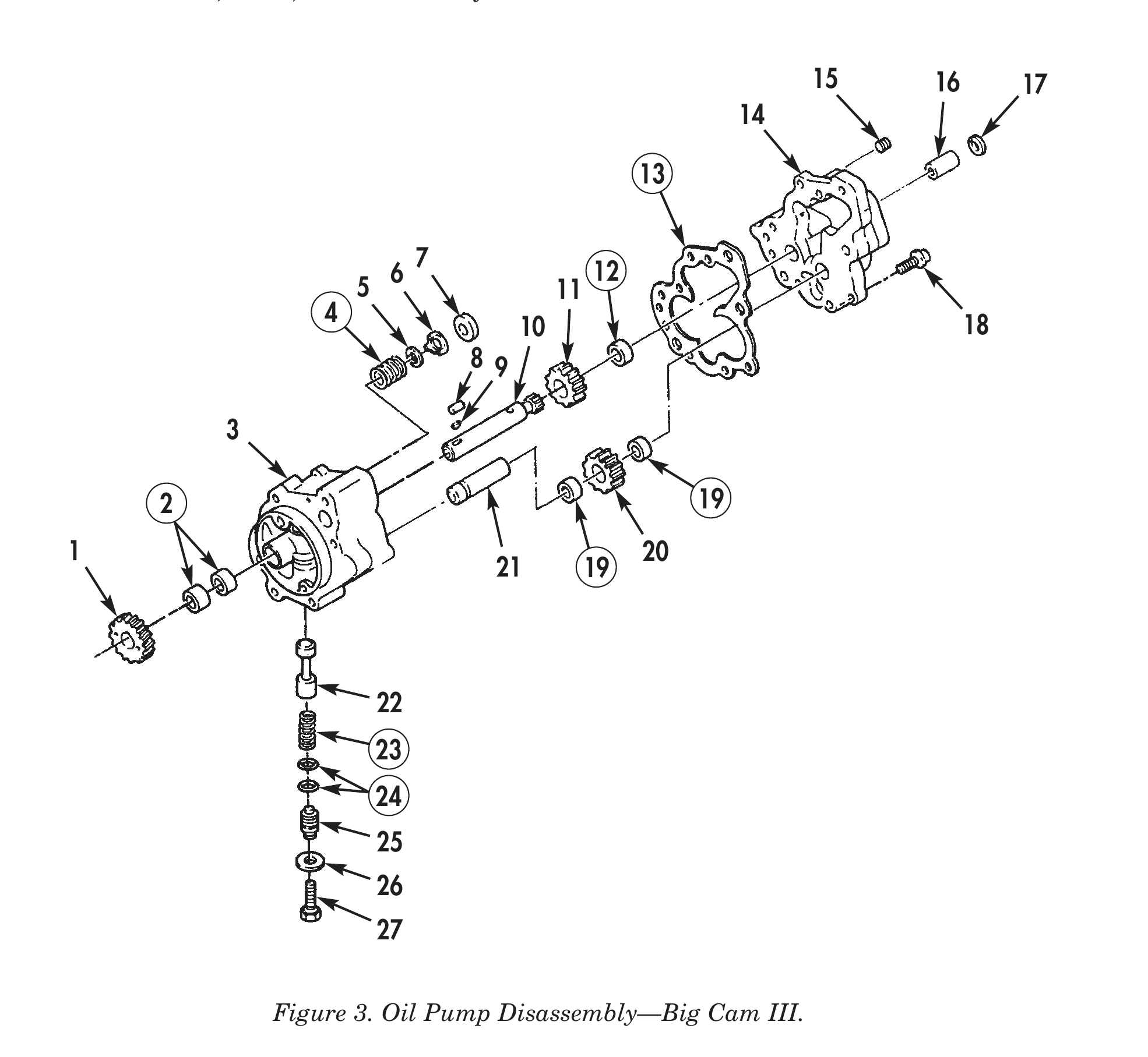
2. Using gear puller, remove oil pump drive gear (1) from oil pump driveshaft (10).
3. Remove woodruff key (9) from oil pump driveshaft (10).
4. Remove retaining ring (17) and coupling (16) from oil pump driveshaft (10).
5. Remove pipe plug (15) from oil pump cover (14).
6. Remove screw (27), washer (26), retainer (25), pressure regulator spring (23), and plunger (22) from oil pump body (3). Discard pressure regulator spring (24).
7. Remove two O-rings (24) from retainer (25). Discard O-rings (24).
8. Remove seven screws (18), oil pump cover (14), and gasket (13) from oil pump body (3). Discard gasket (13).
9. Remove dowel pin (8) from oil pump body (3).
10. Remove bypass valve seat (7), bypass valve disc (6), washer (5), and bypass valve spring (4) from oil pump body (3). Discard bypass valve spring (4),
11. Using press, remove oil pump driveshaft (10), with oil pumping gear (11) attached, from oil pump body (3).
12. Using press, remove oil pump driveshaft (10), from oil pumping gear (11).
13. Remove idler gear (20) from idler shaft (21).
14. Using press, remove idler shaft (21) from oil pump body (3).
15. Using press and mandrel, remove two bushings (2) from oil pump body (3). Discard bushings (2).
16. Using press and mandrel, remove bushing (12) from oil pump cover (14). Discard bushings (12) and (19).
17. Using press and mandrel, remove two bushings (21) from idler gear (20). Discard bushing (21).
Cleaning and Inspection
1. For general parts cleaning information, refer to CLEANING, WP 0051 00.
2. For general parts inspection information, refer to INSPECTION, WP 0051 00.
3. Inspect oil pump drive gear (11) and idler gear (20) for cracks and stripped or chipped teeth.
4. Inspect oil pump body (3) and oil pump cover (14) for cracks and stripped or elongated threaded bolt holes. Repair all stripped or elongated threaded bolt holes.
5. Inspect dowel pin (8) for cracks or distortion.
BIG CAM III (Contd)
Cleaning and Inspection (Contd)
6. Inspect coupling (16) for cracks or stripped teeth.
7. Inspect oil pump driveshaft (10) and idler shaft (21) for galling, breaks, cracks, or bends.
8. Using micrometer or equivalent, measure oil pump driveshaft (10) and idler shaft (21) outside diameter. Minimum outside diameter is 0.874 in (22.20 mm).
9. Inspect woodruff key (9) for damage and woodruff key slot on oil pump driveshaft (10). Replace woodruff key (9) and oil pump driveshaft (10) if woodruff key (9) fits loose in slot.
10. Inspect pressure regulator plunger (22) for movement in bore of oil pump body (3). Replace pressure regulator plunger (22) if it sticks, binds, or is excessively loose.
11. Inspect bypass valve disc (6) for movement in bore of oil pump body (3). Replace bypass valve disc (6) if it sticks, binds, or is excessively loose.
15 16 17
6 12 5 11 4 18 8 9
2 19 1 20 21 19
BIG CAM III (Contd)
Assembly
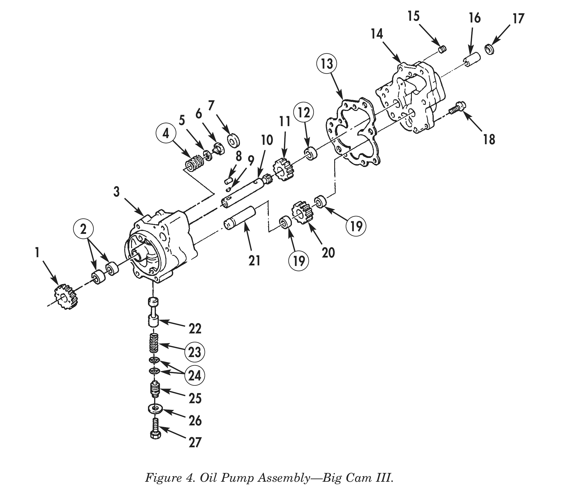
1. Using press and mandrel, install two new bushings (5) and (19) in idler gear (20). Do not press bushing (19) more than 0.020 in. (0.508 mm) below top surface of idler gear (20). Using drill press and reamer, line-ream inside diameter of bushing (19) to 0.8767–0.8777 in. (22.268–22.293 mm).
2. Using press and mandrel, install two new bushings (2) in oil pump body (3). Do not press bushings (2) more than 0.020 in. (0.508 mm) below top surfaces of oil pump body (3). Using drill press and reamer, line-ream inside diameter of bushings (2) to 0.8767–0.8777 in. (22.268–22.293 mm).
3. Using press and mandrel, install new bushing (12) in oil pump cover (14). Do not press bushing (12) more than 0.020 in. (0.508 mm) below top surfaces of oil pump cover (14). Using drill press and reamer, line-ream inside diameter of bushing (12) to 0.8767–0.8777 in. (22.268–22.293 mm).
4. Using press, install oil pumping gear (11) on oil pump driveshaft (10).
5. Using press, install oil pump driveshaft (10) with oil pumping gear (11) attached, in oil pump body (3) until oil pump driveshaft (10) protrudes 1.035–1.055 in. (2.629–2.680 cm) above oil pump body (3).
6. Using press, install idler shaft (21) with large end facing up, in oil pump body (3) until large end protrudes 0.9375–1.0 in. (23.81–25.40 mm) above oil pump body (3).
7. Install idler gear (20) on idler shaft (21).
8. Using feeler gauge, check oil pumping gear (11) to oil pump body (3) clearance. Clearance should be 0.060–0.070 in. (1.52–1.78 mm). Remove and install oil pumping gear (11) until correct clearance is obtained.
9. Install new bypass spring (4), washer (5), bypass valve disc (6), and bypass valve seat (7) in oil pump body (3).
10. Install dowel pin (9) in oil pump body (3).
11. Install new gasket (13) and oil pump cover (14) on oil pump body (3) with seven screws (18). Tighten screws (18) 35 lb-ft (48 N•m).
12. Install two new O-rings (24) on retainer (25).
13. Install plunger (22), new pressure regulator spring (23), retainer (25), washer (26), and screw (27) in oil pump body (3).
BIG CAM III (Contd)
Assembly (Contd)
14. Using pipe sealant, install pipe plug (15) in oil pump cover (14). Tighten plug (15) 30 lb-ft (41 N•m).
15. Install coupling (16) and snapring (17) on oil pump driveshaft (10).
16. Install woodruff key (9) in oil pump driveshaft (10).
17. Using press, install oil pump drive gear (1) on oil pump driveshaft (10).
18. Using a dial indicator, check oil pump driveshaft (10) end play. End play should be between 0.002–0.008 in. (0.05–0.20 mm).
19. For oil pump installation, refer to WP 0042 00.
15 16 17
6 12 5 11 4 18 8 9
2 19 1 20 21 19
END OF WORK PACKAGE