TURBOCHARGER HT-3B
TM 9-2815-225-34&P · Work Package 0027 00
DISASSEMBLY, CLEANING AND INSPECTION, ASSEMBLY
INITIAL SETUP
Tools and Special Tools                                Materials/Parts (Contd)
 General mechanic’s tool kit:                           Sleeve bushing
    automotive (Item 1, WP 0061 00)                       (Item 15, Table 11, WP 0062 00)
 Maintenance and repair shop equipment:                 Lubricating oil OE/HDO 10
    automotive (Item 2, WP 0061 00)                       (Item 19, WP 0060 00)
 Automotive maintenance and repair                      Antiseize compound (Item 7, WP 0060 00)
    supplemental set no. 2 (Item 3, WP 0061 00)         Crocus cloth (Item 4, WP 0060 00)
 Turbocharger mounting plate
    (Item 19, WP 0061 00)                              Equipment Condition
 Ball joint vise (Item 9, WP 0061 00)                   Turbocharger HT-3B removed from engine
                                                          (WP 0009 00).
Materials/Parts
 Four retaining rings
   (Item 1, Table 11, WP 0062 00)
 Two seal rings (Item 2, Table 11, WP 0062 00)
 Seal (Item 3, Table 11, WP 0062 00)
 Two sleeve bearings
   (Item 4, Table 11, WP 0062 00)
 Thrust collar (Item 5, Table 11, WP 0062 00)
 Locknut (Item 6, Table 11, WP 0062 00)
 Ten lockwashers
   (Item 7, Table 11, WP 0062 00)
 Retaining ring (Item 8, Table 11, WP 0062 00)
 Oil seal plate (Item 9, Table 11, WP 0062 00)
 Oil slinger (Item 10, Table 11, WP 0062 00)
 O-ring (Item 11, Table 11, WP 0062 00)
 Oil baffle (Item 12, Table 11, WP 0062 00)
 Thrust bearing
   (Item 13, Table 11, WP 0062 00)
 Seal ring (Item 14, Table 11, WP 0062 00)
DISASSEMBLY
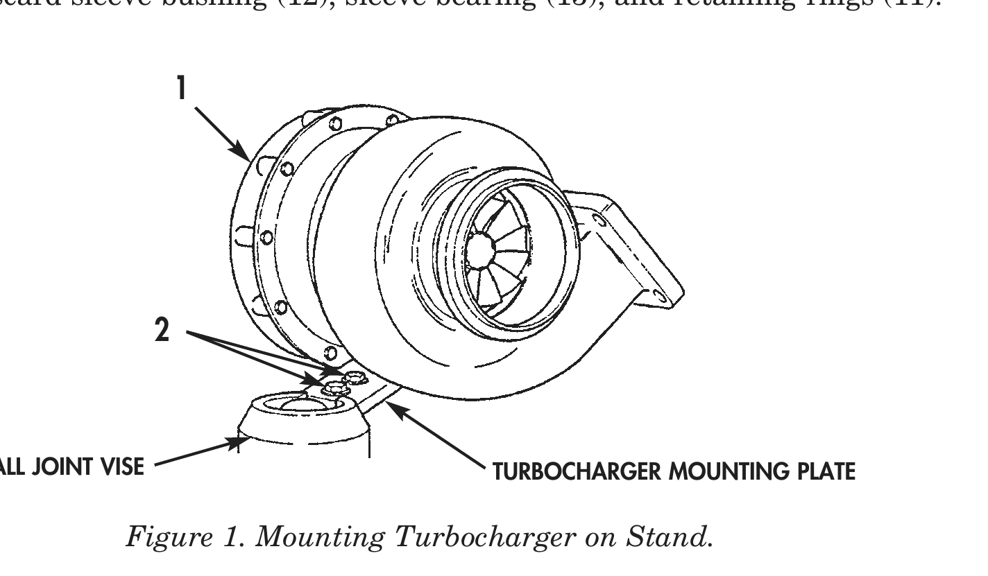
1. Install turbocharger HT-3B assembly (1) on turbocharger mounting plate and ball joint vise with two bolts (2).
2. Scribe a locating mark (6) on impeller housing (3), bearing housing (4), and turbine housing (5) to aid in assembly.
3. Remove ten screws (20), lockwashers (21), two clamping plates (22), and impeller housing (3) from bearing housing (4). Discard lockwashers (21).
4. Remove nut (15), V-band clamp (14), and turbine housing (5) from bearing housing (4).
5. Remove locknut (23) and impeller (24) from wheel and shaft (7). Discard locknut (23).
6. Remove wheel and shaft (7) from bearing housing (4).
7. Remove two seal rings (8) from wheel and shaft (7). Discard seal rings (8).
8. Remove retaining ring (25) and oil seal plate (26) from bearing housing (4). Discard retaining ring (25).
9. Remove O-ring (29) from oil seal plate (26). Discard O-ring (29) and oil seal plate (26).
10. Remove oil slinger (28) and seal ring (27) from bearing housing (4). Discard oil slinger (28) and seal ring (27)
11. Remove oil baffle (30), thrust bearing (31), thrust collar (19), and two dowel pins (16) from bearing housing (4). Discard oil baffle (30), thrust bearing (31), and thrust collar (19).
12. Remove two retaining rings (17) and sleeve bearing (18) from bearing housing (4). Discard sleeve bearings (18) and retaining rings (17).
13. Remove seal (9) and heat shield (10) from bearing housing (4). Discard seal (9).
14. Remove two retaining rings (11), sleeve bushing (12), and sleeve bearing (13) from bearing housing (4). Discard sleeve bushing (12), sleeve bearing (13), and retaining rings (11).
BALL JOINT VISE TURBOCHARGER MOUNTING PLATE
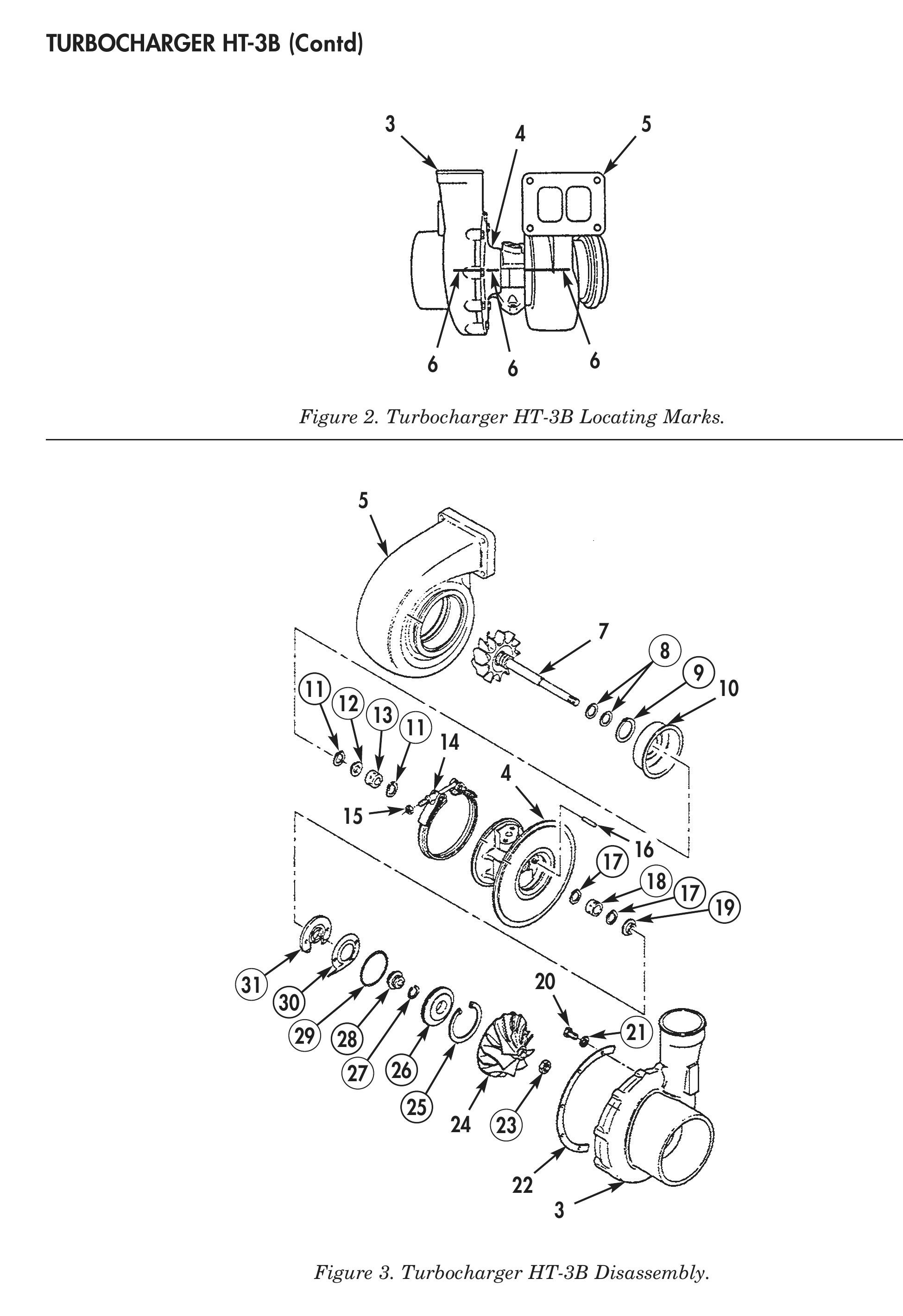
Figure 2. Turbocharger HT-3B Locating Marks.
Figure 3. Turbocharger HT-3B Disassembly.
CLEANING AND INSPECTION
1. For general parts cleaning information, refer to CLEANING, WP 0051 00.
2. For general parts inspection information, refer to INSPECTION, WP 0051 00.
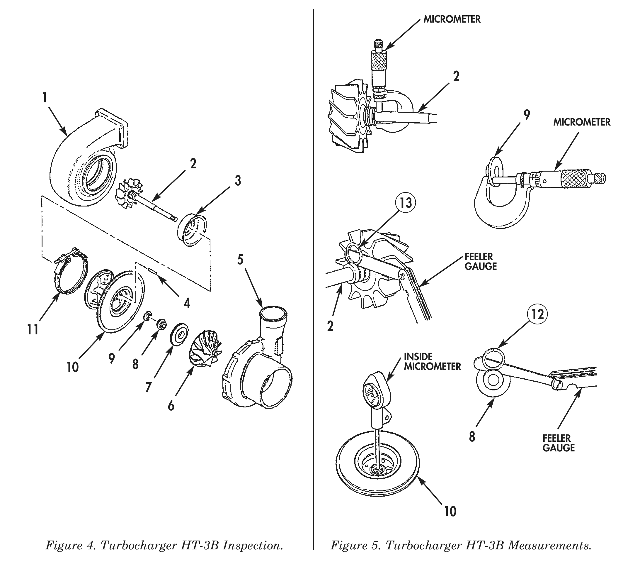
3. Inspect impeller housing (5) and turbine housing (1) for cracks, chips, and scratches. Use crocus cloth to remove small scratches and chips from machined surfaces.
4. Inspect impeller (6) and wheel and shaft (2) vanes for cracks and chips.
5. Inspect two dowel pins (4) for cracks, chips, and bends.
6. Inspect V-band clamp (11) for cracks, chips, bends, or separation.
7. Inspect heat shield (3) for cracks and chips.
8. Using a straightedge, inspect heat shield (3) for straightness and warpage. Discard heat shield (3) if warped.
9. Inspect oil seal plate (7) for cracks, chips or galled bore.
10. Inspect bearing housing (10) for cracks, chips, and scratches.
11. Inspect bearing housing (10) for notches in dome area. Discard if notches are found.
12. Using inside micrometer, measure bearing housing (10) bore inside diameter. Replace bearing housing (10) if inside diameter is more than 0.876 in. (22.268 mm).
13. Using feeler gauge, insert outside edge of feeler gauge and new seal ring (13) in wheel and shaft (2) seal ring grooves. Replace wheel and shaft (2) if seal ring clearance is more than 0.0005 in. (0.13 mm).
14. Using micrometer, measure wheel and shaft (2) bearing area outside diameter. Replace wheel and shaft (2) if bearing area outside diameter is less than 0.5611 in. (14.252 mm).
15. Using micrometer, measure thrust collar (9) thickness. Replace thrust collar (9) if thickness is less than 0.0980 in. (2.489 mm).
16. Using feeler gauge, insert outside edge of feeler gauge and new seal ring (12) in oil slinger (8) seal ring groove. Replace oil slinger (8) if seal ring clearance is more than 0.0005 in. (0.13 mm).
MICROMETER
9        MICROMETER
5                                      FEELER
GAUGE
11 2
9 INSIDE
10 8 MICROMETER
8             FEELER
GAUGE
Figure 5. Turbocharger HT-3B Measurements.
ASSEMBLY
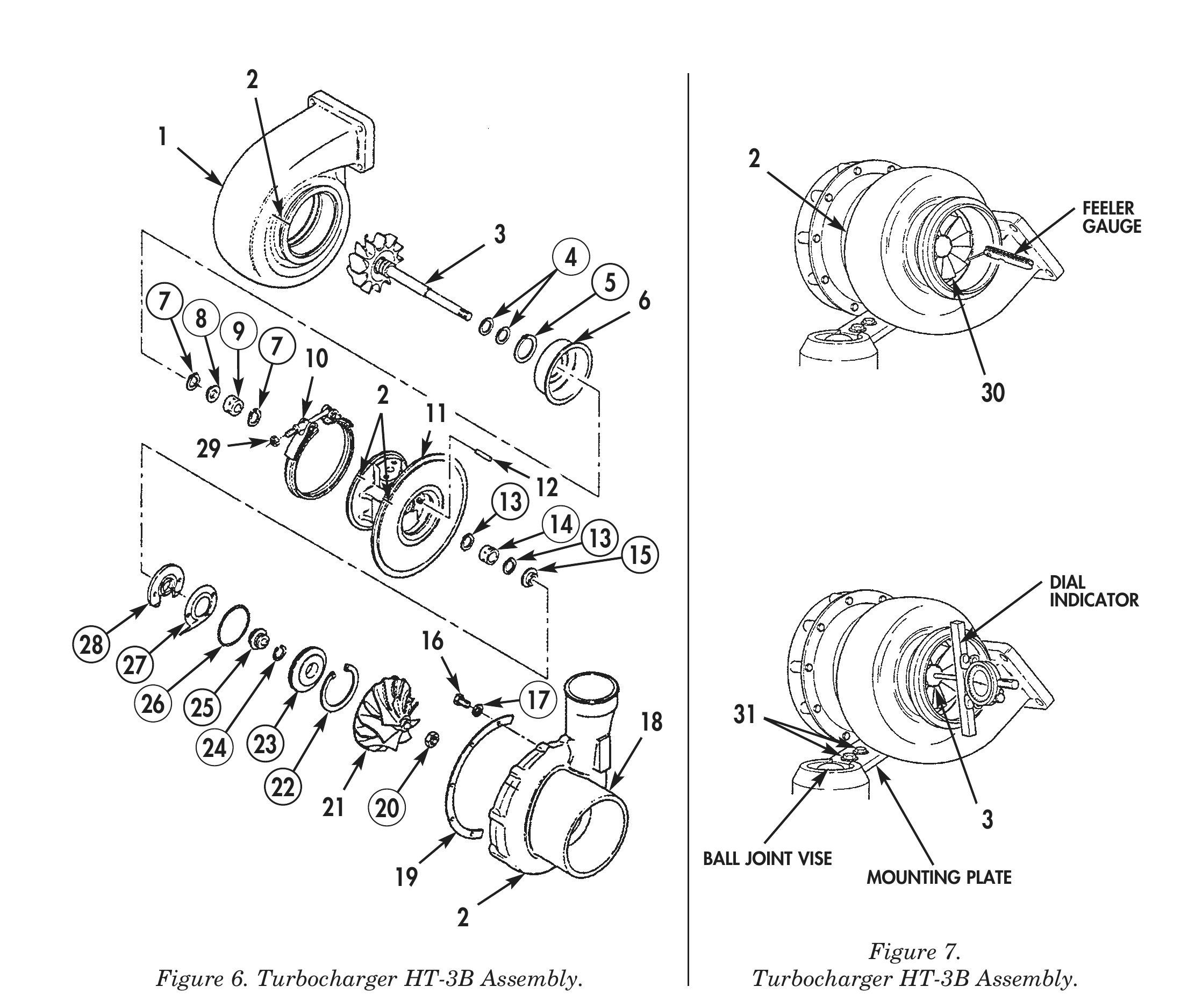
1. Install two new retaining rings (7), new sleeve bearing (9), and new sleeve bushing (8) in bearing housing (11).
2. Install heat shield (6) and new seal ring (5) in bearing housing (11).
3. Install two new retaining rings (13) and new sleeve bearing (14) in bearing housing (11).
4. Install two dowel pins (12), new thrust collar (15), and new thrust bearing (28) in bearing housing (11).
5. Position new oil baffle (27) in bearing housing (11).
6. Install new seal ring (24) on new oil slinger (25), and install new O-ring (26) on new oil seal plate (23).
7. Install oil slinger (25), oil seal plate (23), and new retaining ring (22) in bearing housing (11).
8. Install two new seal rings (4) on wheel and shaft (3).
9. Install wheel and shaft (3) in bearing housing (11) heat shield (6) side.
10. Install impeller (21) and new locknut (20) on wheel and shaft (3). Tighten locknut (20) 30 lb-ft (41 N•m).
11. Apply antiseize compound to threads on V-band clamp (10) and to mating surfaces of turbine housing (1) and bearing housing (11).
12. Position V-band clamp (10) on bearing housing (11).
13. Align scribe mark (2) on turbine housing (1) with scribe mark (2) on bearing housing (11). Install turbine housing (1) on bearing housing (11) with V-band clamp (10) and nut (29). Tighten nut (29) 10 lb-ft (13.6 N•m).
14. Align scribe mark (2) on impeller housing (18) with scribe mark (2) on bearing housing (11). Install impeller housing (18) on bearing housing (11) with two clamping plates (19), ten new lockwashers (17), and screws (16). Tighten screws (16) 5 lb-ft (6.8 N•m).
15. Using feeler gauge, check turbine blade (30)-to-turbine housing (2) clearance. Minimum clearance allowed is 0.008 in. (0.20 mm).
ASSEMBLY (Contd)
16. Using feeler gauge, check impeller (19)-to-impeller housing (18) clearance. Minimum clearance allowed is 0.006 in. (0.15 mm).
17. Using dial indicator, check wheel and shaft (3) end play. Wheel and shaft (3) end play should be 0.001–0.004 in. (0.254–0.1 mm).
18. Remove two bolts (31), turbocharger mounting plate, and turbocharger HT-3B from ball joint vise.
19. For turbocharger HT-3B installation, refer to WP 0046 00.
FEELER
GAUGE
7 6 7 10 2 30
DIAL
INDICATOR
28 16 26 25 17 18 31 24 23 21 20 3
BALL JOINT VISE
19                                                      MOUNTING PLATE
Figure 6. Turbocharger HT-3B Assembly.
Figure 7. Turbocharger HT-3B Assembly.
END OF WORK PACKAGE