ENGINE RETARDER
TM 9-2815-225-34&P · Work Package 0030 00
DISASSEMBLY, CLEANING AND INSPECTION, ASSEMBLY
INITIAL SETUP
Tools and Special Tools                              Equipment Condition
 General mechanic’s tool kit:                         Engine brake retarder removed from engine
    automotive (Item 1, WP 0061 00)                     (WP 0011 00).
 Maintenance and repair shop equipment:
    automotive (Item 2, WP 0061 00)
 Automotive maintenance and repair
    supplemental set no. 2 (Item 3, WP 0061 00)
 Solenoid valve wrench (Item 6, WP 0061 00)
 C-clamp (Item 7, WP 0061 00)

Materials/Parts
 OE/HDO 10 lubricating oil
   (Item 19, WP 0060 00)
 Six outer control valve springs
   (Item 1, Table 14, WP 0062 00)
 Six inner control valve springs
   (Item 2, Table 14, WP 0062 00)
 Six upper seal rings
   (Item 3, Table 14, WP 0062 00)
 Six center seal rings
   (Item 4, Table 14, WP 0062 00)
 Six lower seal rings
   (Item 5, Table 14, WP 0062 00)
 Six slave piston springs
   (Item 6, Table 14, WP 0062 00)
 Six master piston springs
   (Item 7, Table 14, WP 0062 00)
 Six locknuts (Item 8, Table 14, WP 0062 00)
DISASSEMBLY
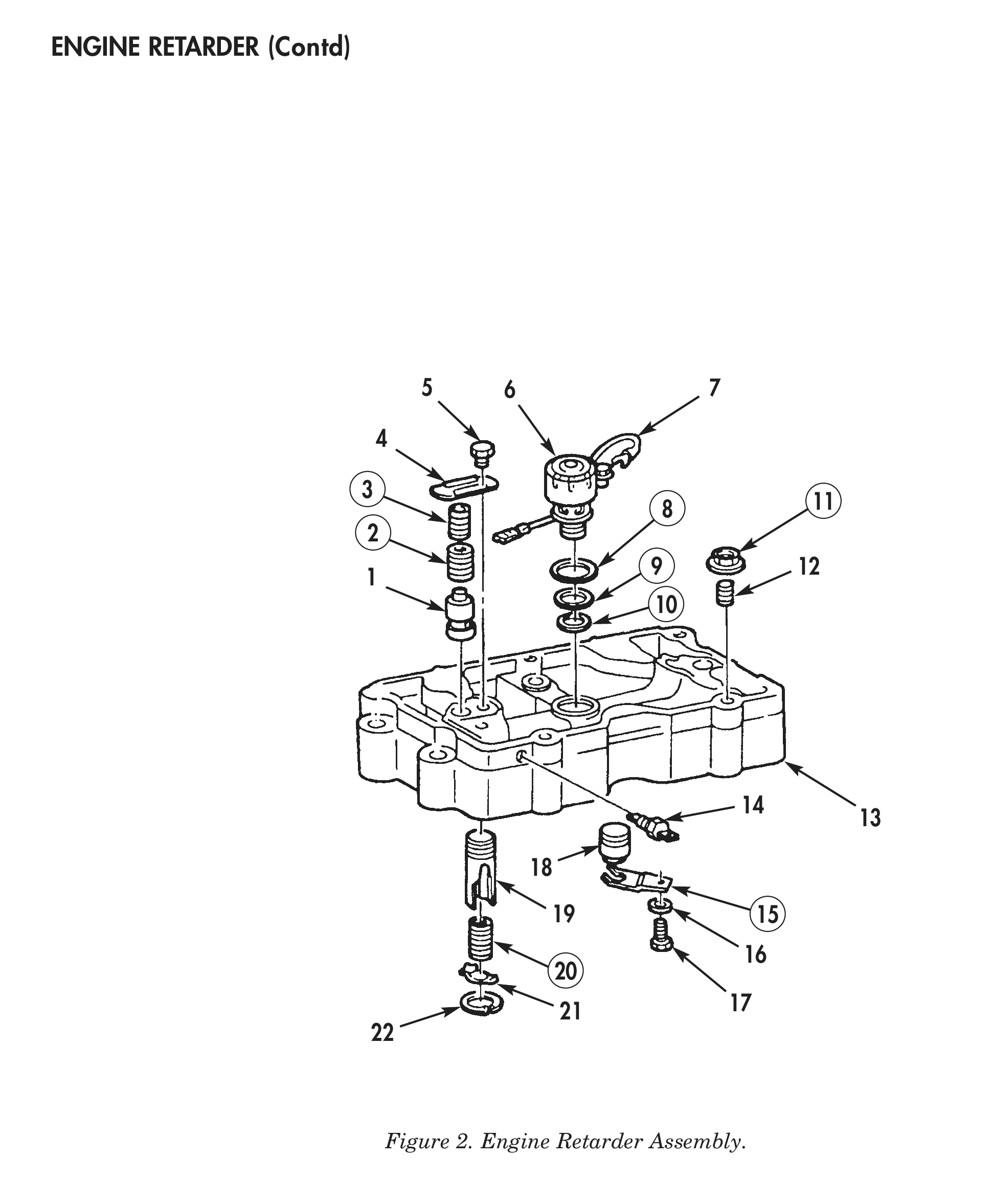
1. Remove two screws (5) and control valve covers (4) from brake housing (13).
2. Remove two outer control valve springs (2) and two inner control valve springs (3) from brake housing (13). Discard outer control valve springs (2) and inner control valve springs springs (3).
3. Remove two control valves (1) from brake housing (13).
4. Disconnect electrical harness (7) from solenoid valve (6).
5. Using solenoid valve wrench, remove solenoid valve (6) from brake housing (13).
6. Remove lower seal ring (10), center seal ring (9), and upper seal ring (8) from solenoid valve (6). Discard seal rings (10), (9), and (8).
7. Remove two screws (17), washers (16), master piston springs (15), and master pistons (18) from brake housing (13). Discard springs (15).
8. Remove two locknuts (11) from setscrews (12) and brake housing (13). Discard locknuts (11).
9. Remove two setscrews (12) from brake housing (13).
10. Using a C-clamp and deep-welled socket, compress slave piston spring (20) and remove retaining ring (22) from brake housing (13). Slowly release slave piston spring (20) pressure and remove C-clamp and deep-welled socket.
11. Remove slave piston retainer (21), slave piston spring (20), and slave piston (19) from brake housing (13). Discard spring (20).
12. Remove electrical terminal (14) from brake housing (13).
13. Repeat steps 1 through 12 for remaining two engine retarders.
CLEANING AND INSPECTION
1. For general parts cleaning information, refer to CLEANING, WP 0051 00.
2. For general parts inspection information, refer to INSPECTION, WP 0051 00.
3. Inspect slave piston retainers (21) for cracks, breaks, or bends.
4. Inspect brake housing (13) for cracks, breaks, stripped threaded holes, and scores or scratches in piston bores. Repair any stripped threaded holes.
5. Ensure control valves (1), master pistons (18), and slave pistons (19) move freely in the bores. Replace control valves (1), master pistons (18), or slave pistons (19) if any binding occurs.
ASSEMBLY
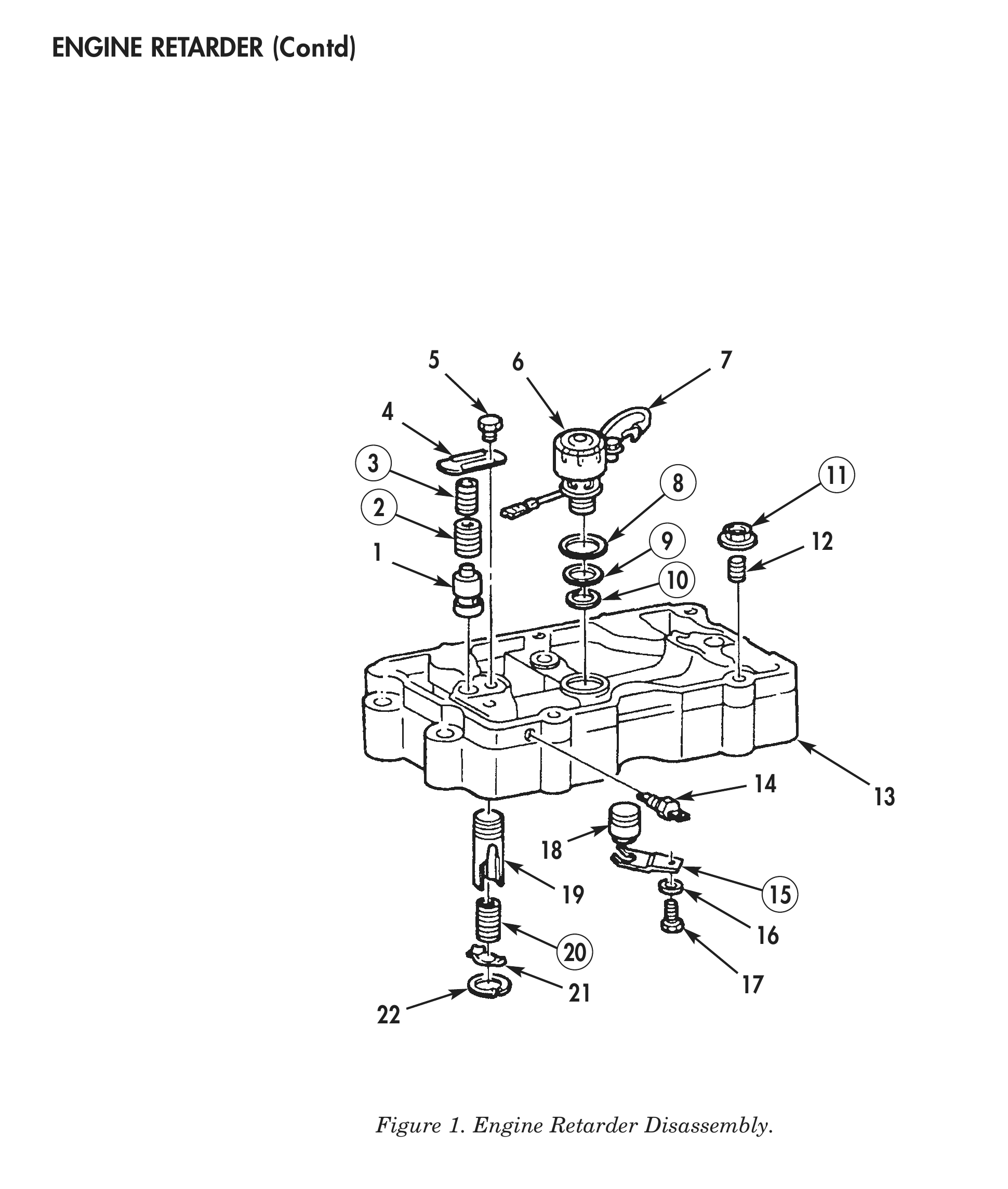
1. Install electrical terminal (14) in brake housing (13).
2. Install slave piston (19), new slave piston spring (20), and slave piston retainer (21) in brake housing (13).
3. Using a C-clamp and deep-welled socket, compress slave piston spring (20) and install retaining ring (22) in brake housing (13). Slowly release slave piston spring (20) pressure and remove C-clamp and deep-welled socket.
4. Install two setscrews (12) in brake housing (13). Do not tighten setscrews (12).
5. Install two new locknuts (11) on setscrews (12). Do not tighten locknuts (11).
6. Install two master pistons (18), new master piston springs (15), washers (16), and screws (17) in brake housing (13).
7. Apply OE/HDO 10 lubricating oil on new upper seal ring (8), new center seal ring (9), and new lower seal ring (10), and install on solenoid valve (6).
8. Using solenoid valve wrench, install solenoid valve (6) in brake housing (13).
9. Connect electrical harness (7) to solenoid valve (6).
10. Install two control valves (1) in brake housing (13).
11. Install two new inner control valve springs (3) and two new outer control valve springs (2) on top of control valve (1) in brake housing (13).
12. Install control valve cover (4) on brake housing (13) with two screws (5).
13. Repeat steps 1 through 12 for remaining two engine retarders.
14. For engine retarder installation, refer to WP 0043 00.