FRONT GEAR COVER
TM 9-2815-225-34&P · Work Package 0028 00
DISASSEMBLY, CLEANING AND INSPECTION, ASSEMBLY
INITIAL SETUP
Tools and Special Tools                             Equipment Condition
 General mechanic’s tool kit: automotive             Front gear cover removed from engine
    (Item 1, WP 0061 00)                               (WP 0012 00).
 Maintenance and repair shop equipment:
    automotive (Item 2, WP 0061 00)
 Automotive maintenance and repair
    supplemental set no. 2 (Item 3, WP 0061 00)
 Puller/installer (Item 33, WP 0061 00)
 Mandrel (Item 39, WP 0061 00)
 Oil seal expander
     (Item 29, WP 0061 00)
 Press

Materials/Parts
 Pipe sealant (Item 25, WP 0060 00)
 Oil seal (Item 1, Table 12, WP 0062 00)
 Crankshaft oil seal
   (Item 2, Table 12, WP 0062 00)
 O-ring (Item 3, Table 12, WP 0062 00)
 Sleeve bushing (Item 4, Table 12, WP 0062 00)
DISASSEMBLY
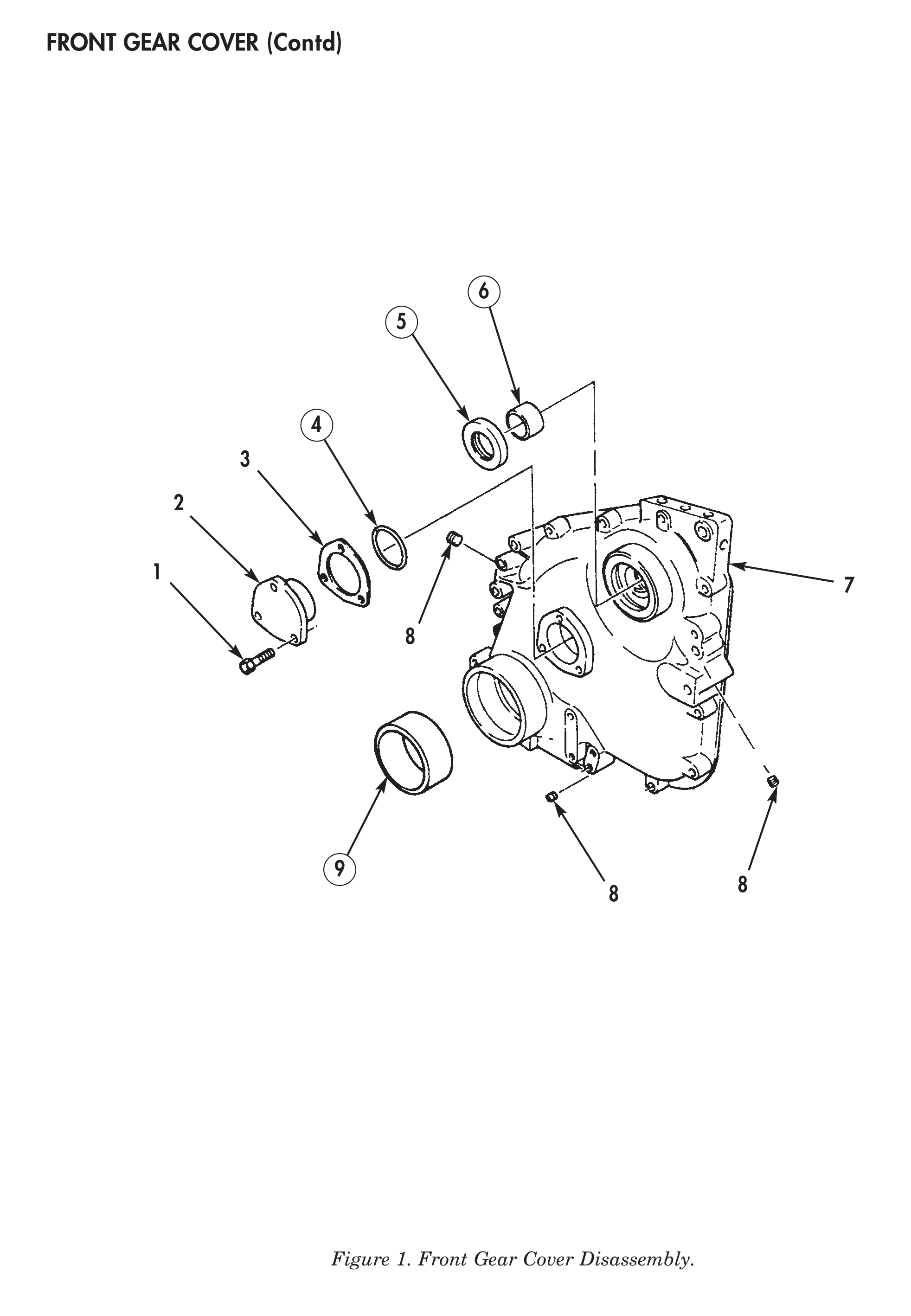
1. Using puller/installer, remove accessory drive oil seal (5) from front gear cover (7). Discard oil seal (5).
2. Using puller/installer, remove crankshaft oil seal (9) from front gear cover (7). Discard crankshaft oil seal (9).
3. Remove three screws (1), camshaft support (2), and shims (3) from front gear cover (7).
4. Remove O-ring (4) from camshaft support (2). Discard O-ring (4).
5. Remove three threaded plugs (8) from front gear cover (7).
6. Using mandrel and press, remove sleeve bushing (6) from front gear cover (7). Discard sleeve bushing (6).
CLEANING AND INSPECTION
1. For general parts cleaning information, refer to CLEANING, WP 0051 00.
2. For general parts inspection information, refer to INSPECTION, WP 0051 00.
3. Using inside micrometer, measure inside diameter of camshaft support (2). Maximum inside diameter is 1.757 in. (4.46 cm).
4. Inspect camshaft support (2) for cracks, scoring, or pitting.
5. Inspect front gear cover (7) for cracks, distortion, stripped or elongated bolt holes, or stripped holes. Repair any stripped holes.
ASSEMBLY
1. Align oil holes in new sleeve bushing (6) with oil holes in front gear cover (7).
2. Using mandrel and press, install sleeve bushing (6) in front gear cover (7).
3. Apply pipe sealant to three threaded plugs (8) and install in front gear cover (7).
4. Install new O-ring (4) on camshaft support (2).
5. Install shims (3) and camshaft support (2) on front gear cover (7) with three screws (1). Tighten screws (1) 25 lb-ft (34 N•m).
6. Using puller/installer and oil seal expander, install new crankshaft oil seal (9) in front gear cover (7).
7. Using puller/installer, install new accessory drive oil seal (5) in front gear cover (7). Ensure oil seal (5) is flush with edge of front gear cover (7).
8. Install front gear cover on engine (WP 0042 00).
8 8
END OF WORK PACKAGE