ENGINE ACCESSORIES INSTALLATION
TM 9-2815-225-34&P · Work Package 0045 00
AIR AFTERCOOLER, FUEL PUMP AND FUEL LINES,
VIBRATION DAMPER AND CRANKSHAFT PULLEY
INITIAL SETUP
Tools and Special Tools                             Equipment Condition
 General mechanic’s tool kit: automotive             Engine mounted on maintenance stand
    (Item 1, WP 0061 00)                               (WP 0009 00)
 Maintenance and repair shop equipment:
    automotive (Item 2, WP 0061 00)                 References
 Automotive maintenance and repair                   TM 9-2320-273-20
    supplemental set no. 2 (Item 3, WP 0061 00)      TM 9-2320-283-20
 Air compressor wrench (Item 18, WP 0061 00)

Material/Parts
 Lubricating oil (Item 19, WP 0060 00)
 High pressure lubricant (Item 15, WP 0060 00)
 Three gaskets (Item 1, Table 28, WP 0062 00)
 Three lockwashers
   (Item 2, Table 28, WP 0062 00)
 Gasket (Item 3, Table 28, WP 0062 00)
 Lockwasher (Item 4, Table 28, WP 0062 00)
 Three lockwashers
   (Item 5, Table 28, WP 0062 00)
 Two lockwasher
   (Item 6, Table 28, WP 0062 00)
 Lockwasher (Item 7, Table 28, WP 0062 00)
AIR AFTERCOOLER
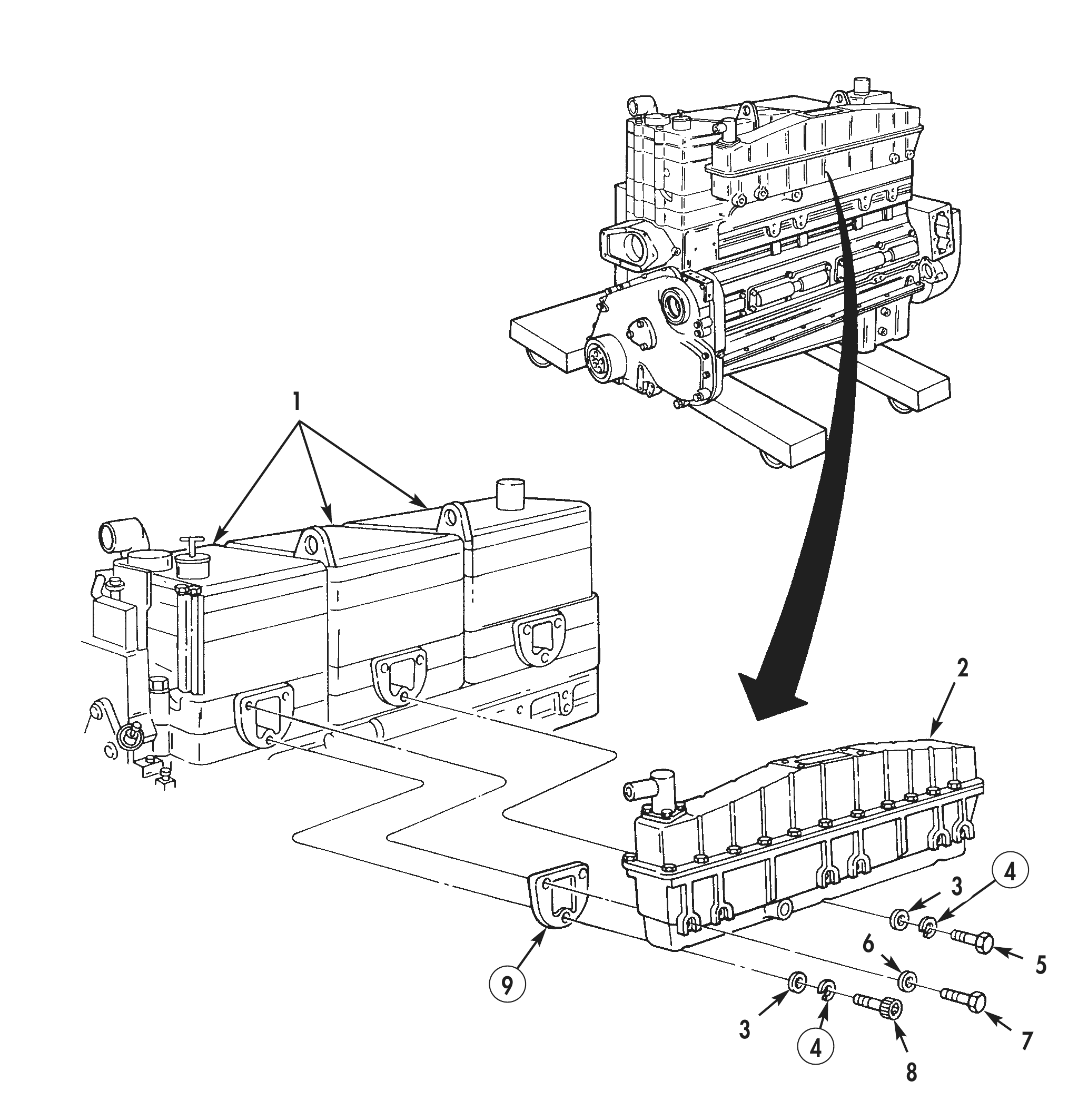
1. Apply a small amount of high pressure lubricant to three new gaskets (9) on cylinder heads (1).
2. Install air aftercooler (2) on cylinder heads (1) with six washers (6) and screws (7). Tighten screws (7) 20–25 lb-ft (27–34 N•m).
3. Install screw (8), two screws (5), three new lockwashers (4) and washers (3) on bottom of each cylinder head (1). Thread in screws (8) and (5) three to five times. Tighten screws (8) and (5) 20–25 lb-ft (27–34 N•m).
4. Install air aftercooler (2) on cylinder heads (1) with six washers (6) and bolts (7).
5. Install three washers (3), new lockwashers (4) and bolts (5) on three outside holes of air aftercooler (2). Thread in bolts (5) three to five times.
FUEL PUMP AND FUEL LINES
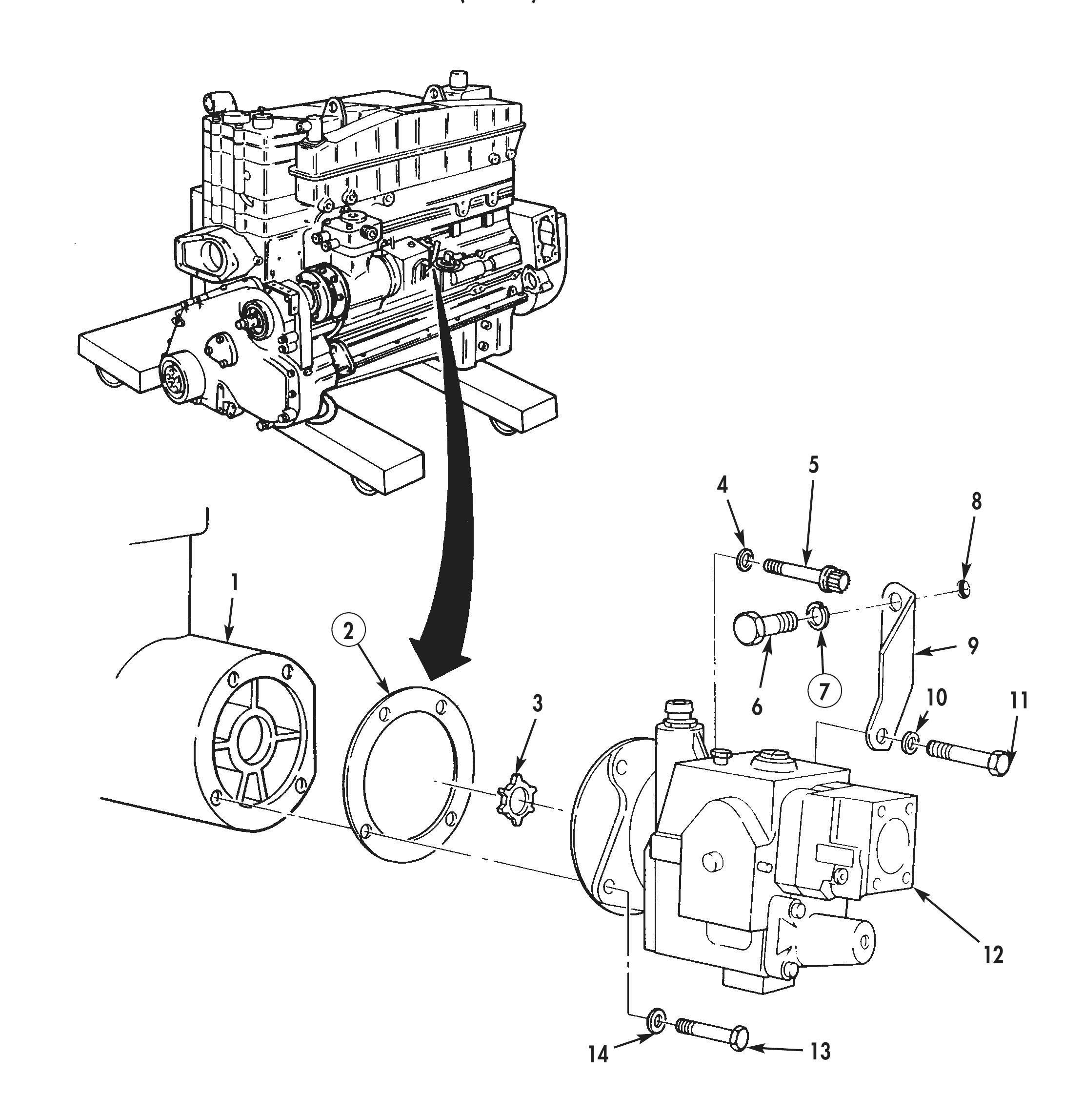
1. Install new gasket (2) and fuel pump (12) with compressor spider coupling (3) on air compressor (1).
2. Position support bracket (9) on fuel pump (12) and air compressor (1) with three washers (10) and bolts (11).
3. Using air compressor wrench, install washer (14) and bolt (13) on fuel pump (12) and into air compressor (1). Tighten bolt (13) finger-tight only.
4. Using air compressor wrench, install support bracket (9) on fuel pump (12) and into air compressor (1) with four washers (4) and bolt (5).
5. Install new lockwasher (7) and bolt (6) on support bracket (9) and cylinder head (8).
FUEL PUMP AND FUEL LINES (Contd)
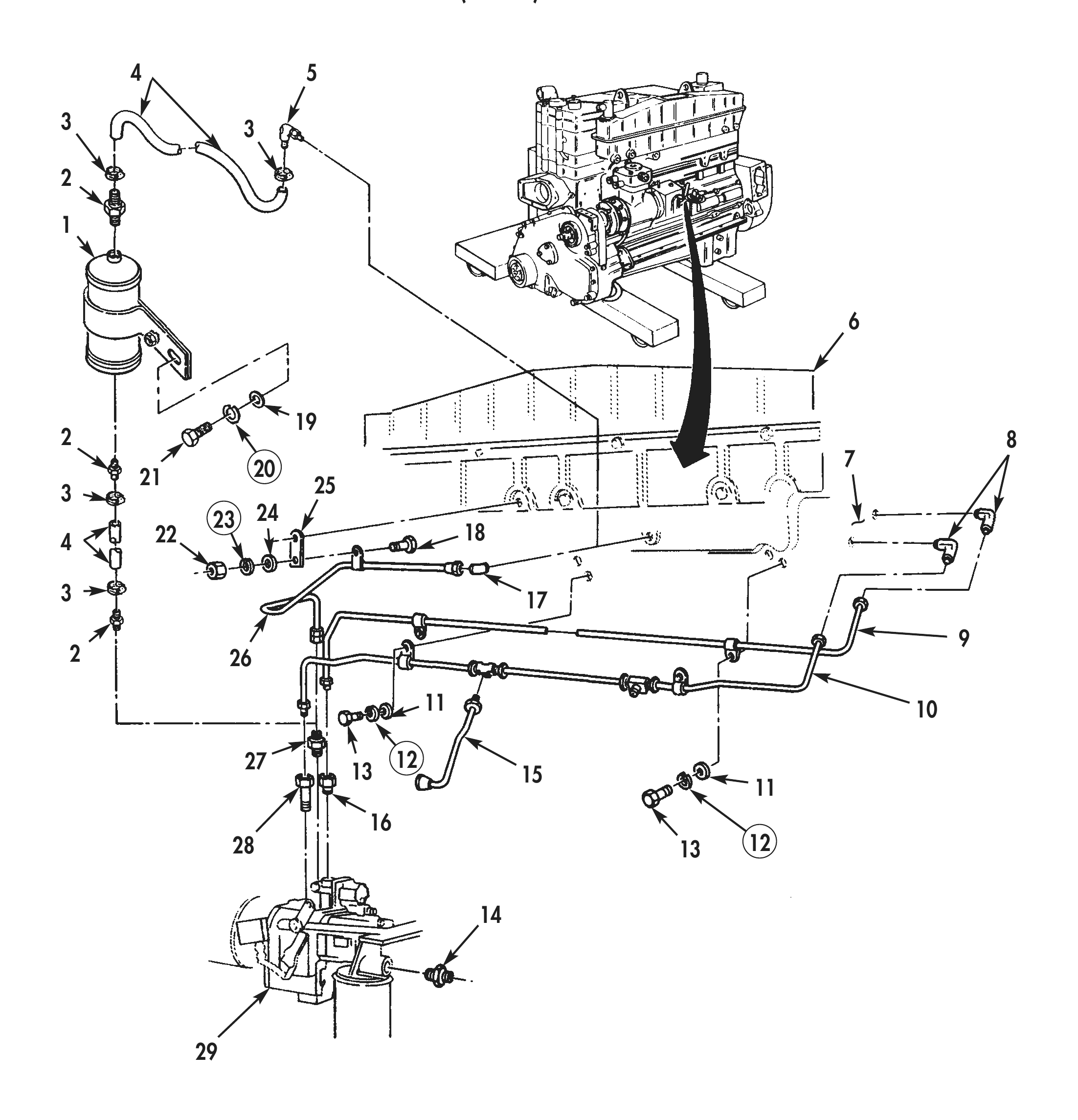
6. Install fuel pump adapter (14) on fuel pump (29).
7. Install two cylinder head adapters (8), fuel supply line (9), and fuel return line (10) on cylinder head (7).
8. Install fuel pump adapter (16) and fuel supply line (9) on fuel pump (29).
9. Install fuel pump adapter (28) and fuel return lines (10) and (15) on fuel pump (29).
10. Install fuel supply line (9) and fuel return line (10) on air aftercooler (6) with two washers (11), new lockwashers (12), and screws (13).
11. Install valve (27) and air supply line (26) on fuel pump (29).
12. Install adapter (17) on air aftercooler (6).
13. Install bracket (25) and air supply line (26) with screw (18), washer (24), new lockwasher (23), and nut (22) on air aftercooler (6).
14. Install ASA air tank (1) with washer (19), new lockwasher (20), and screw (21) on air aftercooler (6).
15. Install ASA hose fittings (2) on ASA air tank (1).
16. Install air aftercooler elbow (5) on air aftercooler (6).
17. Install two air supply hoses (4) and four hose clamps (3) on ASA air tank (1).
VIBRATION DAMPER AND CRANKSHAFT PULLEY
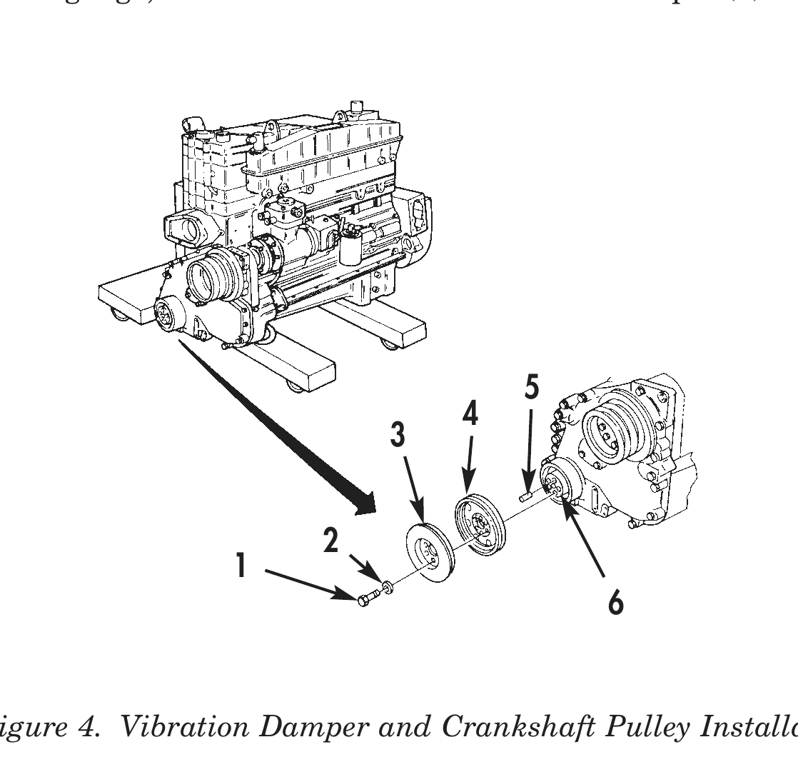
1. Install two vibration damper guide pins (5) on two opposite holes in face of crankshaft (6).
2. Install crankshaft pulley (4) and vibration damper (3) on two guide pins (5) and push into crankshaft (6) until seated.
3. Apply a coat of clean lubricating oil to threads of six screws (1) and washers (2).
4. Install four screws (1) and washers (2) on vibration damper (3), crankshaft pulley (4), and crankshaft (6).
5. Install remaining two screws (1) and washers (2) on vibration damper (3), crankshaft pulley (4), and crankshaft (6). Tighten screws 190 lb-ft (258 N•m).
6. Using dial indicator gauge, measure movement on vibration damper (3) circumference by rotating crankshaft (6).
7. Using dial indicator gauge, measure movement of vibration damper (3) face by rotating crankshaft (6).
END OF WORK PACKAGE