EXHAUST MANIFOLD
TM 9-2815-225-34&P · Work Package 0025 00
DISASSEMBLY, CLEANING AND INSPECTION, ASSEMBLY
INITIAL SETUP
Tools and Special Tools
 General mechanic’s tool kit:
    automotive (Item 1, WP 0061 00)
 Maintenance and repair shop equipment:
    automotive (Item 2, WP 0061 00)
 Automotive maintenance and repair
    supplemental set no. 2 (Item 3, WP 0061 00)

Materials/Parts
 Antiseize compound (Item 7, WP 0060 00)
 Pipe sealant (Item 25, WP 0060 00)
 Two spacer inserts
   (Item 1, Table 9, WP 0062 00)

Equipment Condition
 Exhaust manifold removed from engine
   (WP 0009 00).
DISASSEMBLY
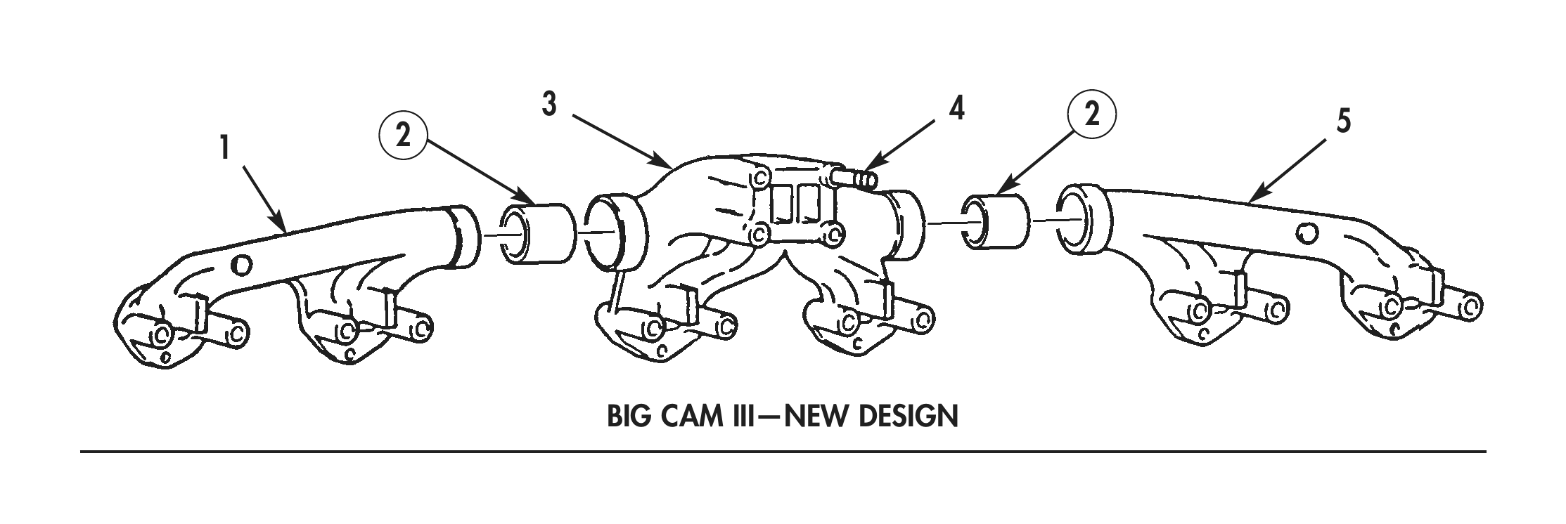
1. Remove front exhaust manifold (1) and rear exhaust manifold (4) from center exhaust manifold (2).
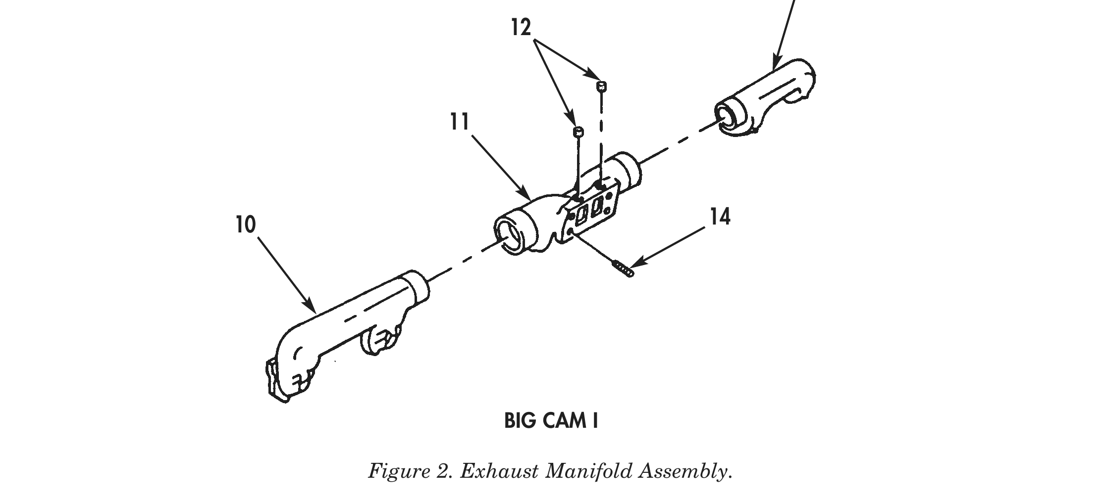
2. Remove two pipe plugs (3) from center exhaust manifold (2).
3. Remove four turbocharger mounting studs (5) from center exhaust manifold (2).
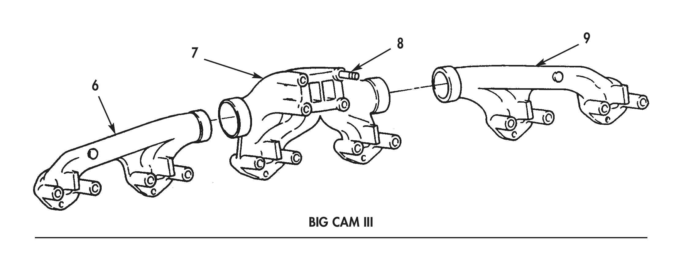
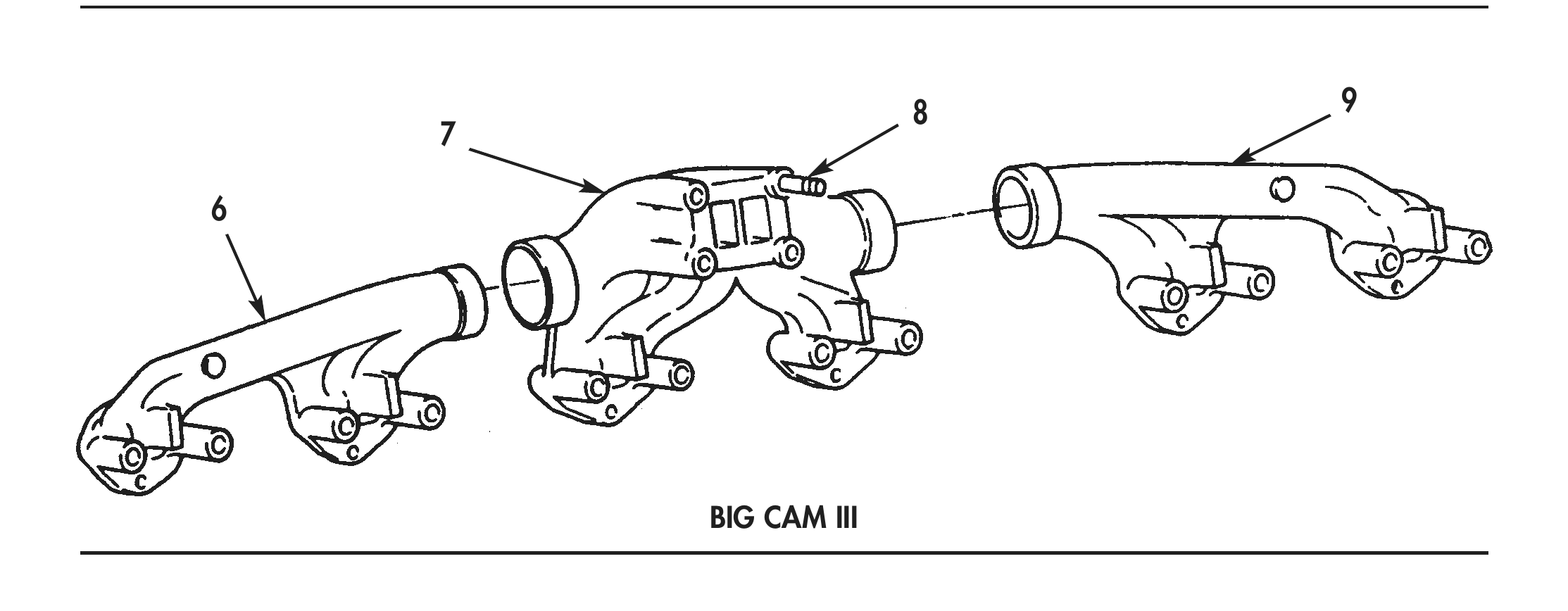
4. Remove front exhaust manifold (6) and rear exhaust manifold (9) from center exhaust manifold (7).
5. Remove four turbocharger mounting studs (8) from center exhaust manifold (7).
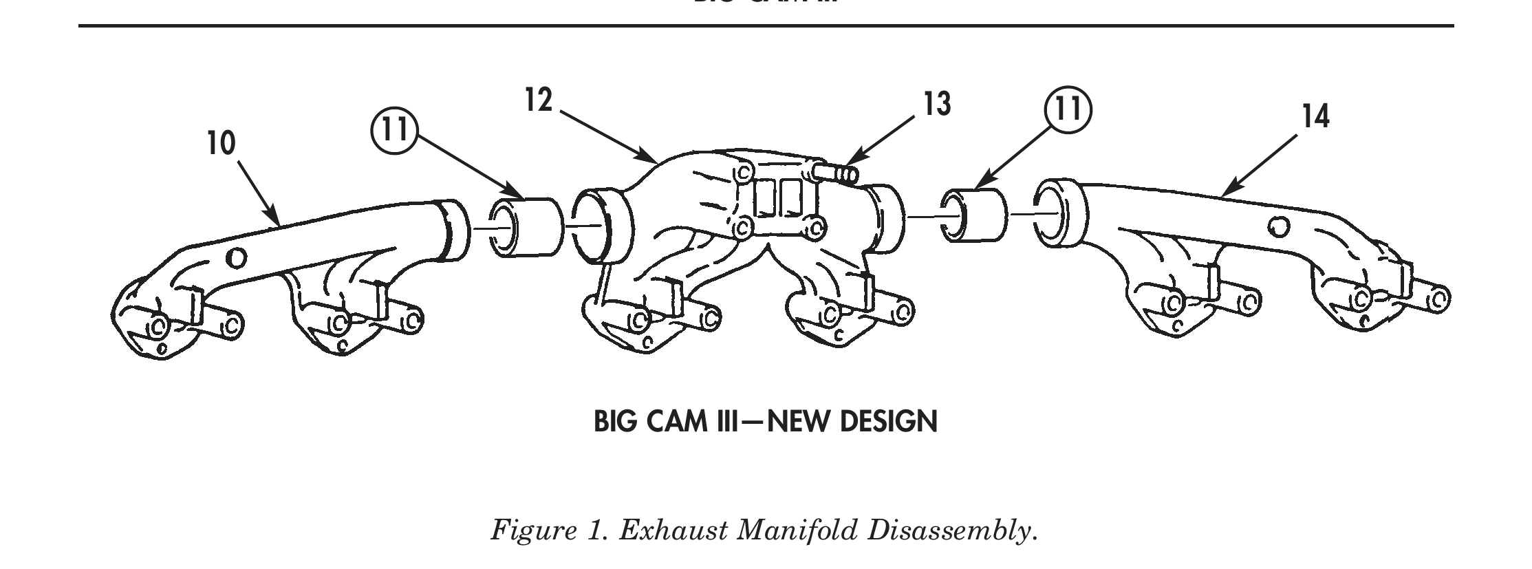
6. Remove front exhaust manifold (10) and rear exhaust manifold (14) from spacer inserts (11).
7. Remove two spacer inserts (11) from center exhaust manifold (12). Discard spacer inserts (11).
8. Remove four turbocharger mounting studs (13) from center exhaust manifold (12).
CLEANING AND INSPECTION
1. For general parts cleaning information, refer to CLEANING, WP 0051 00.
2. For general parts inspection information, refer to INSPECTION, WP 0051 00.
3. Inspect front exhaust manifold (1), (6), and (10), center exhaust manifold (2), (7), and (12), and rear exhaust manifold (4), (9), and (14) for cracks, distortion, and corrosion.
4. Inspect turbocharger mounting studs (5), (8), and (13) for stripped threads. Repair all damaged threads.
5. Inspect center exhaust manifold (2), (7), and (12) for stripped threads or damaged holes. Repair all damaged threads and holes.
ASSEMBLY
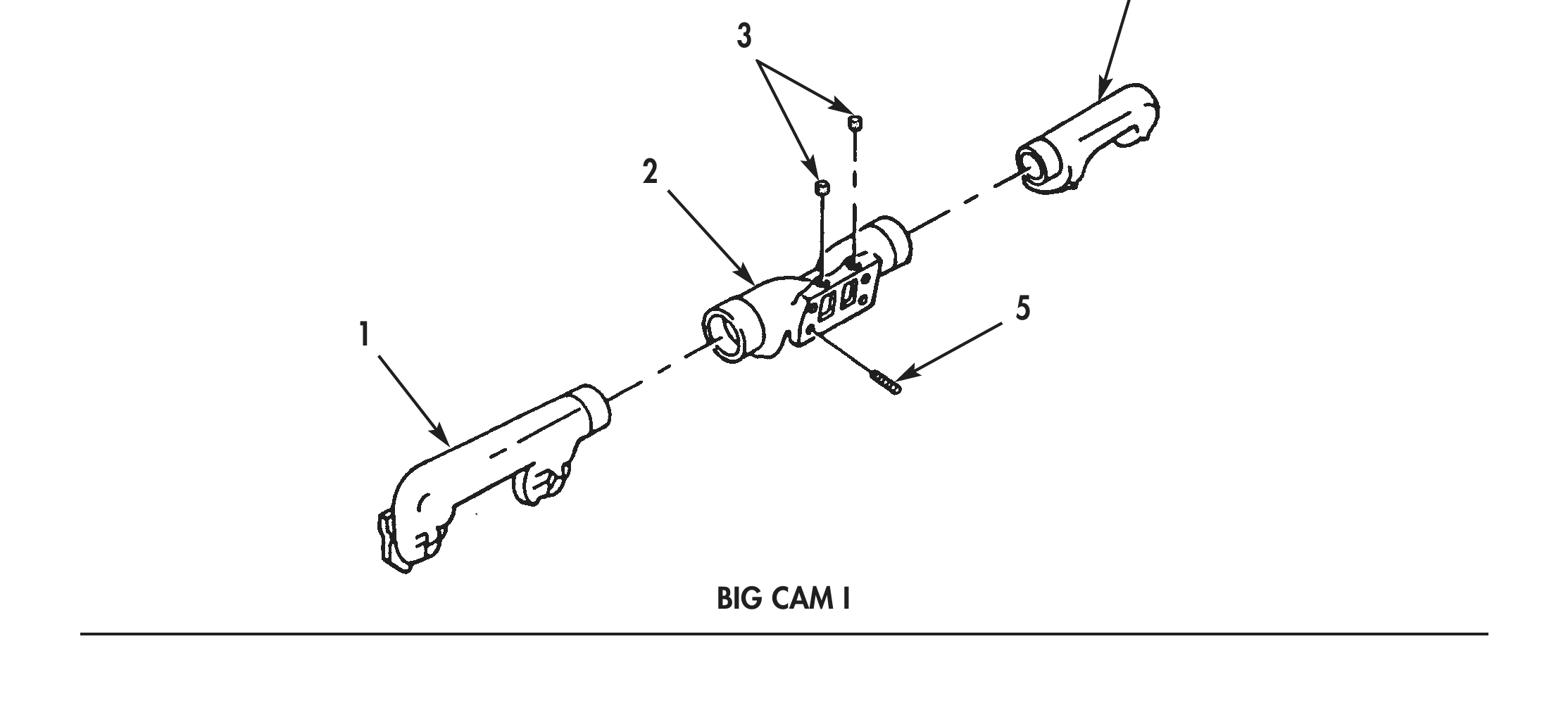
1. Install four turbocharger mounting studs (4) in center exhaust manifold (3).
2. Install two new spacer inserts (2) in center exhaust manifold (3).
3. Apply antiseize compound to mating surfaces of front exhaust manifold (1), spacer inserts (2), and rear exhaust manifold (5).
4. Install front exhaust manifold (1) and rear exhaust manifold (5) on spacer inserts (2).
5. Install four turbocharger mounting studs (8) in center exhaust manifold (7).
6. Apply antiseize compound to mating surfaces of front exhaust manifold (6), center exhaust manifold (7), and rear exhaust manifold (9).
7. Install front exhaust manifold (6) and rear exhaust manifold (9) on center exhaust manifold (7).
8. Install 4 turbocharger mounting studs (14) in center exhaust manifold (11).
9. Apply pipe sealant on 2 pipe plugs (12) and install pipe plugs (12) in center exhaust manifold (11).
10. Apply antiseize compound to mating surfaces of front exhaust manifold (10), center exhaust manifold (11), and rear exhaust manifold (13).
11. Install front exhaust manifold (10) and rear exhaust manifold (13) on center exhaust manifold (11).
12. Install exhaust manifold on engine (WP 0046 00).