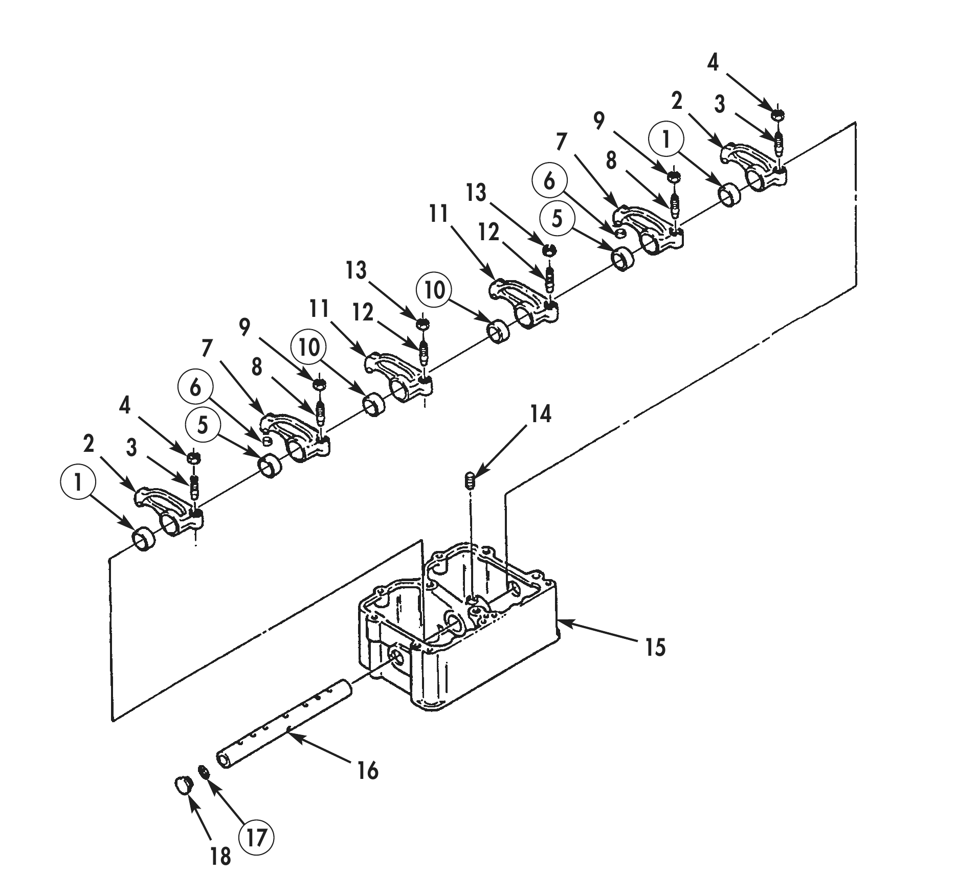
ROCKER LEVERS AND ROCKER LEVER HOUSING
TM 9-2815-225-34&P · Work Package 0020 00
DISASSEMBLY, CLEANING AND INSPECTION, ASSEMBLY
INITIAL SETUP
Tools and Special Tools                              Equipment Condition
 General mechanic’s tool kit:                         Rocker levers and rocker lever housing
    automotive (Item 1, WP 0061 00)                     removed from engine (WP 0012 00).
 Maintenance and repair shop equipment:
    automotive (Item 2, WP 0061 00)
 Automotive maintenance and repair
    supplemental set no. 2 (Item 3, WP 0061 00)
 Rocker lever block and mandrel set
    (Item 30, WP 0061 00)
 0.250 in. (6.350 mm) radius gauge
    (Item 31, WP 0061 00)
 Split rod (Item 32, WP 0061 00)
 Mandrel (Item 39, WP 0061 00)
 Press

Materials/Parts
 Lubricating oil (Item 19, WP 0060 00)
 240-grit aluminum oxide paper
   (Item 22, WP 0060 00)
 Six O-rings (Item 1, Table 5, WP 0062 00)
 Eighteen bushings
   (Item 2, Table 5, WP 0062 00)
 Six ball socket seats
   (Item 3, Table 5, WP 0062 00)
DISASSEMBLY
1. Remove two exhaust rocker lever adjusting screws (3) and nuts (4) from exhaust rocker levers (2).
2. Remove two injector rocker lever adjusting screws (8) and nuts (9) from injector rocker levers (7).
3. Remove two intake rocker lever adjusting screws (12) and nuts (13) from intake rocker levers (11).
4. Remove setscrew (14) from rocker lever shaft (16) and rocker arm housing (15).
5. Using press and mandrel, remove rocker lever shaft (16), two exhaust rocker levers (2), injector rocker levers (7), and intake rocker levers (11) from rocker lever housing (15).
6. Remove two plugs (18) and O-rings (17) from each end of rocker lever shaft (16). Discard O-rings (17) and expansion plugs (18).
7. Using press and rocker lever block and mandrel set, remove two bushings (1) from exhaust rocker levers (2). Discard bushings (1).
8. Using press and rocker lever block and mandrel set, remove two bushings (5) from injector rocker levers (7). Discard bushings (5).
9. Remove two ball socket seats (6) from injector rocker levers (7). Discard ball socket seats (6).
10. Using press and rocker lever block and mandrel set, remove two bushings (10) from intake rocker levers (11). Discard bushings (10).
11. Repeat steps 1 through 10 for remaining two rocker lever housings.
CLEANING AND INSPECTION
1. For general parts cleaning information, refer to CLEANING, WP 0051 00.
2. For general parts inspection information, refer to INSPECTION, WP 0051 00.
3. Inspect rocker lever housing (15) for cracks, breaks, chips, elongated or stripped bolt holes. Repair any damaged bolt holes.
4. Inspect rocker lever housing (15) breather vent hole and oil passages for blockage and obstructions. Clean out breather vent hole and oil passages if obstructed.
5. Inspect rocker lever housing (15) shaft bore, for sharp edges, nicks, or burrs. Rocker lever housing (15) shaft bore should have slight radius. Remove sharp edges, nicks, or burrs with 240-grit aluminum oxide paper attached to a split rod and drill.
6. Using inside micrometer, measure rocker lever housing (15) shaft bore inside diameter. Rocker lever housing (15) shaft bore inside diameter should be 1.1238–1.1246 in. (2.855–2.857 cm). Replace rocker lever housing (15) if rocker lever housing (15) shaft bore inside diameter is not within specifications.
7. Inspect rocker lever shaft (16) for scoring or ridges created from rocker lever movement.
8. Using micrometer, measure rocker lever shaft (16) outside diameter. rocker lever shaft (16) outside diameter should be 1.1230–1.1240 in. (2.552–2.855 cm). Replace rocker lever shaft (16) if outside diameter exceeds 1.1220 in. (2.850 cm).
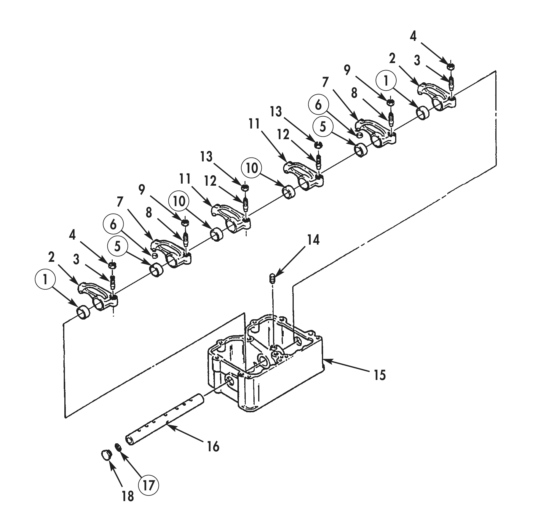
CLEANING AND INSPECTION (Contd)
9. Inspect adjusting screws (3), (8), and (12) for stripped threads.
10. Using a 0.250 in. (6.350 mm) radius gauge, measure adjusting screws (3), (8), and (12) ball end. Replace adjusting screws (3), (8), and (12) if ball end is flat or out-of-round.
11. Inspect adjusting nuts (4), (9), and (13) for stripped threads.
12. Inspect rocker levers (2), (7), and (11) for cracks, bends, or stripped threads.
2 3 7 1 11 5 11 12 7 10 4 14 2 3
ASSEMBLY
1. Using press and rocker lever block and mandrel set, install two new bushings (10) in intake rocker levers (11).
2. Using press and rocker lever block and mandrel set, install two new bushings (1) in exhaust rocker levers (2).
3. Using press and rocker lever block and mandrel set, install two new bushings (5) in injector rocker levers (7).
4. Install two new ball socket seats (6) on injector rocker levers (7).
5. Using press, install two new plugs (18) in ends of rocker lever shaft (16).
6. Position two exhaust rocker levers (2), injector rocker levers (7), and intake rocker levers (11) in their tagged positions in rocker lever housing (15).
7. Install rocker lever shaft (16) through rocker lever housing (15) and two exhaust rocker levers (2), injector rocker levers (7), and intake rocker levers (11). Leave 0.500 in. (12.70 mm) of rocker lever shaft (16) extending out of rocker lever housing (15).
8. Install new O-ring (17) on rocker lever shaft (16) and push rocker lever shaft (16) back through rocker lever housing (15). Leave 0.500 in. (12.70 mm) of rocker lever shaft (16) extending out of rocker lever housing (15) opposite side.
9. Install new O-ring (17) on rocker lever shaft (16) and push rocker lever shaft (16) through rocker lever housing (15) until rocker lever shaft (16) is even with rocker lever housing (15).
10. Install setscrew (14) in rocker lever shaft (16) and rocker arm housing (15).
11. Install two exhaust rocker lever adjusting screws (3) and nuts (4) in exhaust rocker levers (2).
12. Install two injector rocker lever adjusting screws (8) and nuts (9) in injector rocker levers (7).
13. Install two intake rocker lever adjusting screws (12) and nuts (13) in intake rocker levers (11).
14. Repeat steps 1 through 14 for remaining two rocker lever and rocker lever housings.
15. For rocker levers and rocker housing installation, refer to WP 0043 00.