ENGINE TESTING
TM 9-2815-225-34&P · Work Package 0047 00
GENERAL INFORMATION, PRE-TEST INSPECTION, INSTALLATION OF ENGINE ON DYNAMOMETER, CONDITIONS FOR TESTING, FINAL ACCEPTANCE TEST,
BREAK-IN RUNNING, ENGINE TEST, POWER CHECK, SMOKE LEVEL CHECK, FINAL CHECK
INITIAL SETUP
Tools and Special Tools
 General mechanic’s tool kit: automotive
    (Item 1, WP 0061 00)
 Maintenance and repair shop equipment,
    automotive (Item 2, WP 0061 00)
 Automotive maintenance and repair
    supplemental set no. 2 (Item 3, WP 0061 00)
 Manometer (Item 57, WP 0061 00)
 Blow-by check tool (Item 58, WP 0061 00)

Materials/Parts
 Lubricating oil, engine (Item 20, WP 0060 00)
GENERAL INFORMATION
The engine test is a combination of a run-in procedure and a performance check. The run-in procedure provides an operating period that allows engine parts to achieve a final finish and fit. The performance check confirms that the engine will operate at its specified speed and torque rating, that it is leak free, that it is free of abnormal noises, and that its various systems are operating within specified values. In the event of conflicting instructions between this procedure and other references, this procedure will take precedence. Dynamometer must have sufficient capacity to permit testing at 100 percent of engine’s 400 hp @ 2100 rpm.
PRE-TEST INSPECTION
The engine will be inspected for completeness and obvious damage before testing/performance check (no missing accessories, drive belts installed properly, no missing screws or nuts, etc.).
INSTALLATION OF ENGINE ON DYNAMOMETER
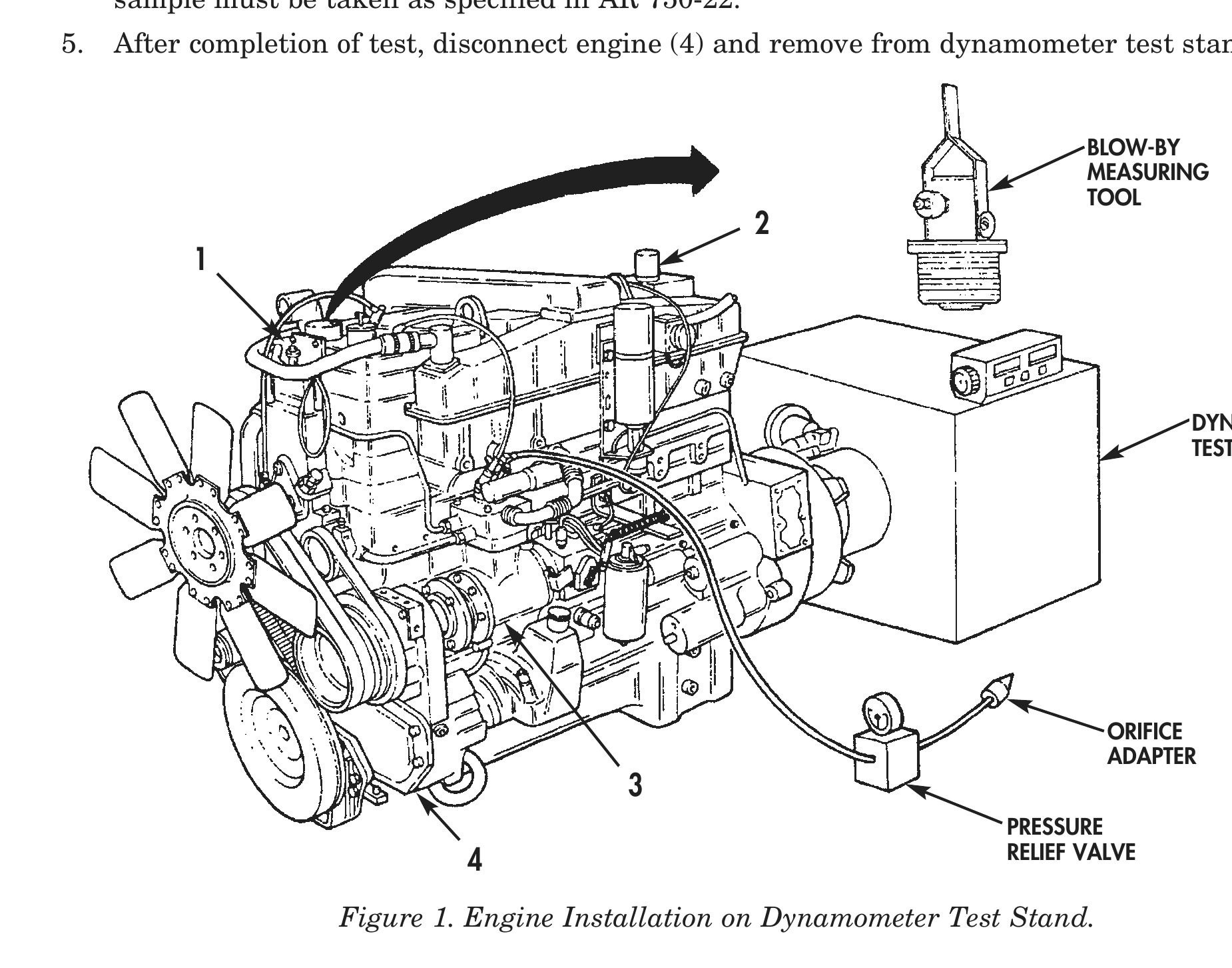
1. Mount engine (4) on dynamometer test stand following manufacturer’s instructions.
2. Cover, or plug, breather tube (2).
3. Install blow-by measuring tool in place of oil filler cap (1).
4. Connect air compressor (3) to a 0.125–0.130 in. (3.175–3.302 mm) diameter orifice adapter located downstream from a 150 psi (1034 kPa) pressure relief valve.
CONDITIONS FOR TESTING
1. Do not run engine (4) with less than 35 psi (241 kPa) of oil pressure.
2. Engine oil pressure must not exceed 90 psi (689.5 kPa) at any time.
3. Engine oil temperature must not exceed 250° F (121° C) at any time.
4. Engine coolant temperature must not exceed 210° F (96.0° C) at any time.
5. Do not run engine (4) under full power/load conditions when oil temperature or coolant temperature is below 190° F (88° C).
6. Do not shut down engine (4) following heavy power/load runs without a minimum of a 5-minute cool-down, no-load run.
FINAL ACCEPTANCE TEST
1. Start engine (4) and operate at idle for 5 minutes. Check for low oil pressure, high coolant temperature, leaks, and unusual noises. No fuel leaks are allowed. Only Class I oil leaks are allowed as described below. CLASS I— Seepage of fluid (as indicated by wetness or discoloration) not great enough to form drops. CLASS II— Leakage of fluid great enough to form drops, but not enough to cause drops to drip from item being checked/inspected. CLASS III—Leakage of fluid great enough to form drops that fall from the item being checked/inspected.
2. Stop engine (4) after 5 minutes of operation. Allow engine (4) to stand for 2 minutes while checking for leaks and unusual conditions.
3. Start engine (4), test, and record results.
4. Prior to removal of engine (4) from dynamometer test stand, whether accepted or rejected, an oil sample must be taken as specified in AR 750-22.
5. After completion of test, disconnect engine (4) and remove from dynamometer test stand.
BLOW-BY
MEASURING
TOOL
DYNAMOMETER
TEST STAND
ORIFICE
ADAPTER
PRESSURE
4                                        RELIEF VALVE
BREAK-IN RUNNING
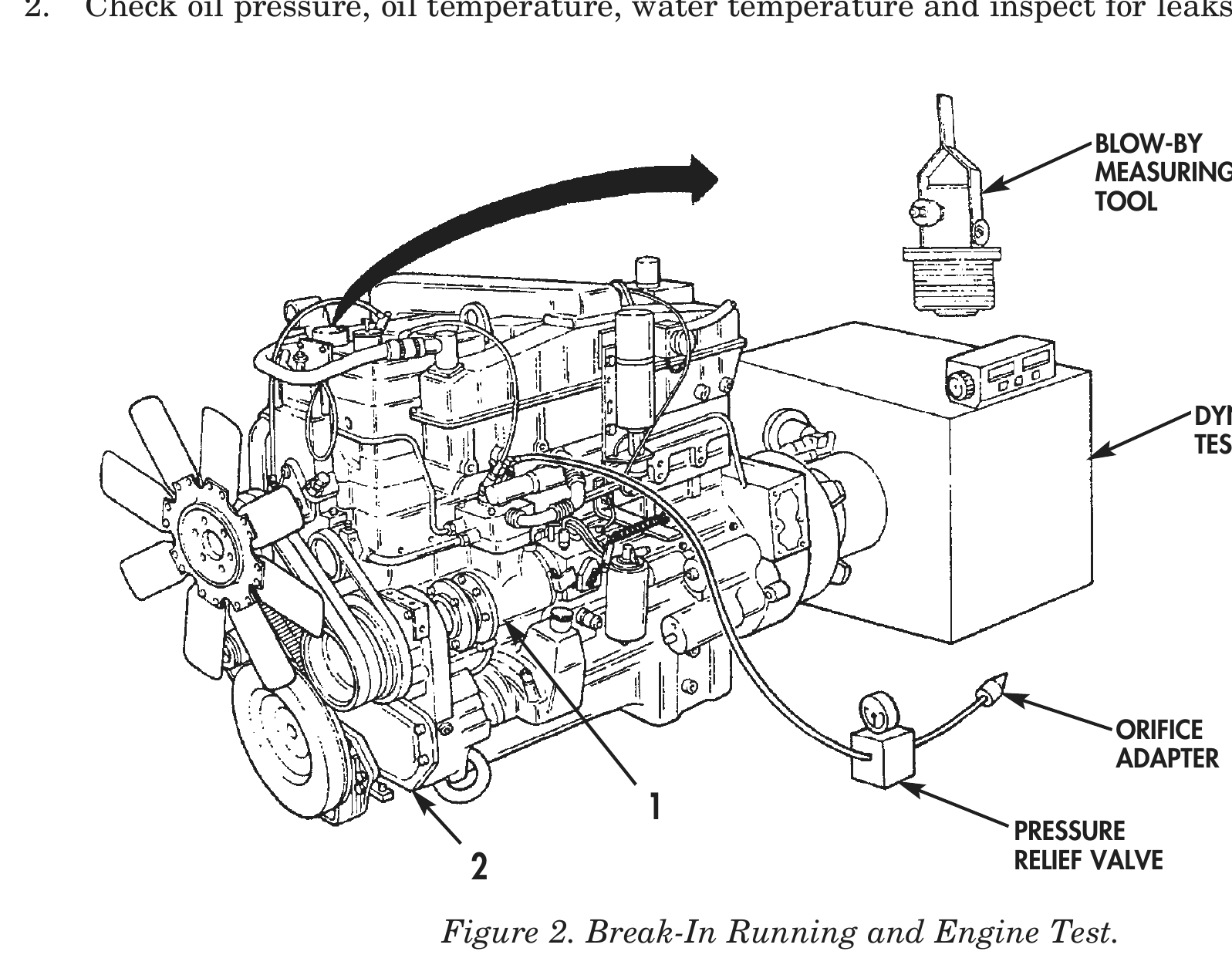
1. Start engine (2) and idle at 1200 rpm no-load for 5–10 minutes. Operate air compressor (1) in pumping mode.
2. Check oil pressure, oil temperature, water temperature and inspect for leaks.
BLOW-BY
MEASURING
TOOL
DYNAMOMETER
TEST STAND
ORIFICE
ADAPTER
PRESSURE
2                                   RELIEF VALVE
ENGINE TEST

                                                     NOTE
                       At each phase, record crankcase pressure blow-by, engine
                       speed, and load at 1 minute intervals. Watch for increases or
                       wide shifts in blow-by pressure. If a sudden increase in blow-by
                       pressure occurs or if blow-by exceeds 12 in. H2O, return to the
                       previous phase test or repeat phase 1 test and operate engine
                       an additional 15 minutes. If blow-by does not reach an
                       acceptable level after repeating test for 15 minutes, discontinue
                       test and determine cause. If blow-by is within an acceptable
                       level, proceed to next phase test.
                       After each test, check for fuel, air, water, oil, or exhaust leaks
                       and correct as necessary.
                       Lubricating oil level is checked only when engine is shut down
                       or incorrect readings on dipstick will result.
                       Refer to Phase 1 Test in Dynamometer Test Chart for steps 1
                       through 7.
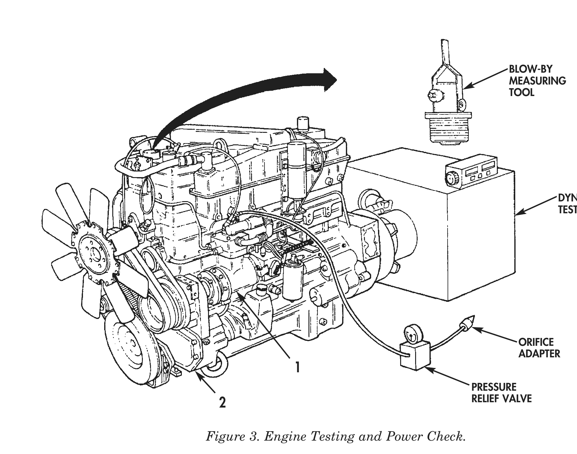
 1.    Apply load to engine (2) at +/- 10 percent horsepower, +/- 5 percent speed.
 2.    Check crankcase pressure with blow-by measuring tool.
 3.    Operate engine (2) until normal oil operating temperature is attained.
 4.    Stop engine (2) and check lubricating oil level.
 5.    Add lubricating oil to bring level up to H (high) on dipstick.
 6.    Allow oil temperature to stabilize.
 7.    Operate air compressor (1) in pumping mode.

                                             Dynamometer Test Chart
                              AIR   CRANKCASE                                                        POWER
                                               PHASE 1           PHASE 2     PHASE 3     PHASE 4
      HP @     FUEL RATE   MANIFOLD PRESSURE                                                          CHECK
                                              160° F HP         2 MIN. HP   5 MIN. HP   4 MIN. HP
      RPM        LB/HR     PRESSURE  W/TURBO                                                        4 MIN. HP
                                                @ RPM             @ RPM       @ RPM       @ RPM
                            IN/HG      T46B                                                          @ RPM
   400                                   12 in.      100          160         260       Full Load    384
               139–145       39/47
  @ 2100                                 H2O        @ 1200       @ 1200      @ 1600      @ 1200     @ 2100
ENGINE TEST (Contd)
8. Apply load to engine (2) at +/- 10 percent horsepower, +/- 5 percent speed.
9. Check pressure with blow-by measuring tool.
10. Set idle speed to 600 rpm and set full load governed speed to 2100 rpm.
11. Adjust load and rpm until specified readings are obtained.
12. Operate air compressor (1) in pumping mode.
13. Apply load to engine (2) at +/- 10 percent horsepower, +/- 5 percent speed.
14. Check crankcase pressure with blow-by measuring tool.
15. Operate air compressor (1) in pumping mode.
16. Apply load to engine (2) at +/- 10 percent horsepower, +/- 5 percent speed.
17. Check crankcase pressure with blow-by measuring tool.
18. Check for leaks and retighten all external screws to correct specifications.
19. Operate air compressor (1) in non-pumping mode.
POWER CHECK
1. Run engine (2) at 2100 rpm for 4 minutes.
2. Check crankcase pressure with blow-by measuring tool. Repeat procedure until engine (2) develops 96–100% rated horsepower at standard fuel rate within permissible crankcase pressure limit. Operate air compressor (1) in non-pumping mode.
3. Apply dynamometer test stand load as engine (2) rpm is increased until rated rpm and horsepower are reached and load is stabilized.
POWER CHECK (Contd)

                                     Dynamometer Test Chart
                          AIR   CRANKCASE                                                          POWER
                                           PHASE 1            PHASE 2     PHASE 3      PHASE 4
   HP      FUEL RATE   MANIFOLD PRESSURE                                                            CHECK
                                          160° F HP          2 MIN. HP   5 MIN. HP    4 MIN. HP
  @ RPM      LB/HR     PRESSURE  W/TURBO                                                          4 MIN. HP
                                            @ RPM              @ RPM       @ RPM        @ RPM
                        IN/HG      T46B                                                            @ RPM
   400                              12 in.         100        160         260         Full Load    384
           139–145      39/47
  @ 2100                            H2O           @ 1200     @ 1200      @ 1600        @ 1200     @ 2100

                                                                                     BLOW-BY
                                                                                     MEASURING
                                                                                     TOOL

                                                                                            DYNAMOMETER
                                                                                            TEST STAND

                                                                                      ORIFICE
                                                                                      ADAPTER
                                             1
                                                                            PRESSURE
                                2                                           RELIEF VALVE

                            Figure 3. Engine Testing and Power Check.
SMOKE LEVEL CHECK
1. Using 0–20 scale on opacity meter, record smoke reading. Specification is 12.84 percent (3.6 percent Bosch).
2. Increase dynamometer test stand load until rpm is reduced to 60 percent of rated rpm.
3. Using 0–20 scale on opacity meter, record smoke reading. Specification is 3.87 percent (1.0 percent Bosch). Remove meter after reading is taken.
4. Reduce dynamometer test stand load and engine (3) rpm.
5. Accelerate engine (3) to rated rpm, no-load and return to idle. Full acceleration should occur in 3–5 seconds.
6. Using 0–100 scale on opacity meter, accelerate engine (3) to rated rpm, no-load and record highest reading. Specification is 22 percent (4.3 percent Bosch).
7. Return engine (3) to idle.
FINAL CHECK
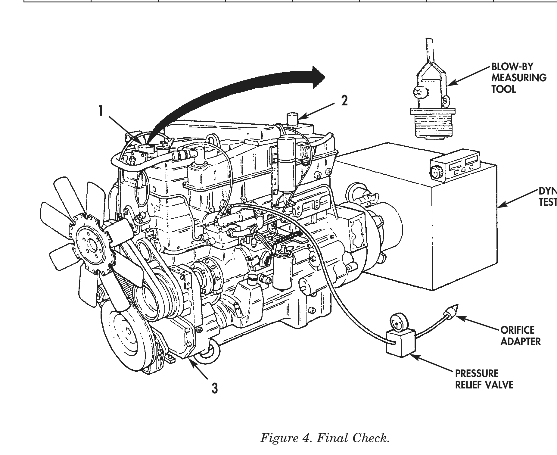
1. Using blow-by measuring tool, check pressure at end of testing procedure. If pressure is greater than specification listed in test chart, run engine (3) for additional 30 minutes at 96–100 percent rated load and rpm.
2. Remove orifice adapter from pressure relief valve.
3. Remove blow-by measuring tool from engine (3) and install oil filler cap (1) on engine (3).
4. Unplug breather tube (2).
FINAL CHECK (Contd)

                                      Dynamometer Test Chart
                           AIR   CRANKCASE                                                      POWER
                                            PHASE 1        PHASE 2     PHASE 3      PHASE 4
   HP       FUEL RATE   MANIFOLD PRESSURE                                                        CHECK
                                           160° F HP      2 MIN. HP   5 MIN. HP    4 MIN. HP
  @ RPM       LB/HR     PRESSURE  W/TURBO                                                      4 MIN. HP
                                             @ RPM          @ RPM       @ RPM        @ RPM
                         IN/HG      T46B                                                        @ RPM
   400                               12 in.     100        160         260         Full Load    384
            139–145      39/47
  @ 2100                             H2O       @ 1200     @ 1200      @ 1600        @ 1200     @ 2100

                                                                                  BLOW-BY
                                                                                  MEASURING
                                                                                  TOOL
                                                     2
            1

                                                                                         DYNAMOMETER
                                                                                         TEST STAND

                                                                                   ORIFICE
                                                                                   ADAPTER

                                                                         PRESSURE
                                 3                                       RELIEF VALVE

                                        Figure 4. Final Check.

END OF WORK PACKAGE