ACCESSORY DRIVE AND ACCESSORY DRIVE PULLEY
TM 9-2815-225-34&P · Work Package 0029 00
DISASSEMBLY, CLEANING AND INSPECTION, ASSEMBLY
INITIAL SETUP
Tools and Special Tools                             Equipment Condition
 General mechanic’s tool kit: automotive             Accessory drive and accessory drive pulley
    (Item 1, WP 0061 00)                               removed from engine (WP 0010 00).
 Maintenance and repair shop equipment:
    automotive (Item 2, WP 0061 00)
 Automotive maintenance and repair
    supplemental set no. 2 (Item 3, WP 0061 00)
 Press
 Mandrel (Item 39, WP 0061 00)

Materials/Parts
 Lubricating oil (Item 19, WP 0060 00)
 Pipe sealant (Item 25, WP 0060 00)
 Sleeve (Item 1, Table 13, WP 0062 00)
 Thrust bearing (Item 2, Table 13, WP 0062 00)
 Thrust bearing (Item 3, Table 13, WP 0062 00)
 Bushing (Item 4, Table 13, WP 0062 00)
DISASSEMBLY
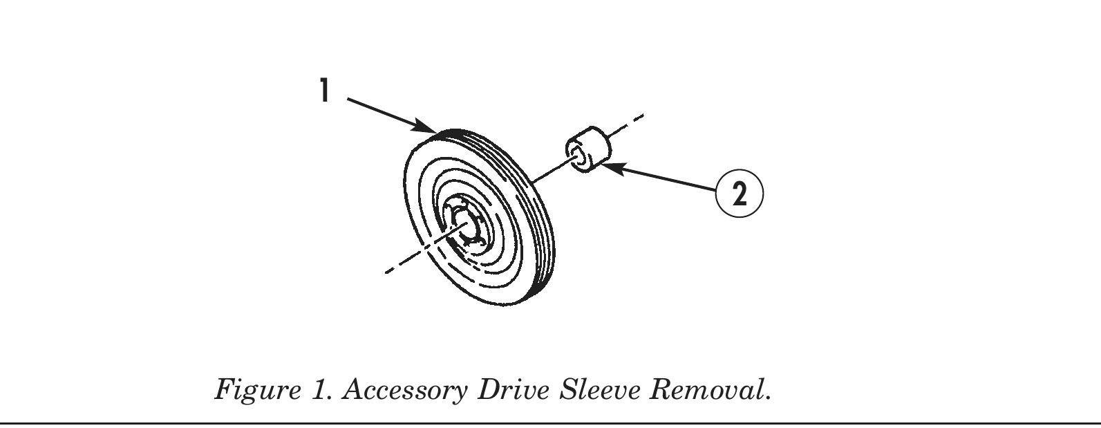
1. Using 3/8 in. (9.525 mm) cold chisel, split and remove sleeve (2) from accessory drive pulley (1). Discard sleeve (2).
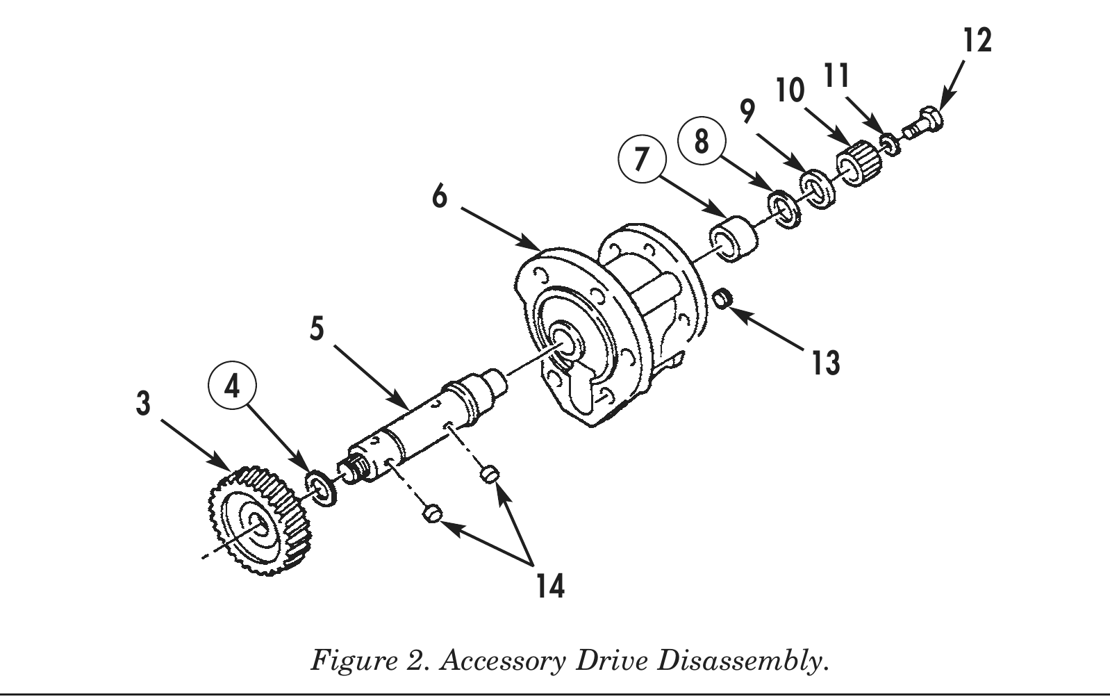
2. Remove screw (12) and washer (11) from accessory drive shaft (5).
3. Install screw (12) in accessory drive shaft (5). Using puller, remove spline coupling hub (10) from accessory drive shaft (5). Remove screw (12) from accessory drive shaft (5).
4. Remove washer (9) and thrust bearing (8) from accessory drive shaft (5). Discard thrust bearing (8).
5. Remove accessory drive shaft (5), with accessory drive gear (3) attached, from accessory drive housing (6).
6. Using press and mandrel, remove accessory drive gear (3) and thrust bearing (4) from accessory drive shaft (5). Discard thrust bearing (4).
7. Remove two dowel pins (14) from accessory drive shaft (5).
8. Using press and mandrel, remove bushing (7) from accessory drive housing (6). Discard bushing (7).
9. Remove threaded plug (13) from accessory drive housing (6).
CLEANING AND INSPECTION
1. For general parts cleaning information, refer to CLEANING, WP 0051 00.
2. For general parts inspection information, refer to INSPECTION, WP 0051 00.
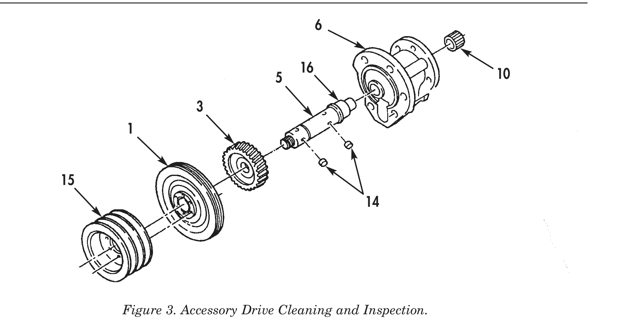
3. Inspect front accessory drive pulley (15) and accessory drive pulley (1) for cracks and chips in hub, worn grooves, and distorted thread holes.
4. Inspect accessory drive housing (6) for cracks, stripped threads, or damaged holes. Repair any damaged threads.
5. Inspect accessory drive gear (3) and spline coupling hub (10) for cracks, chipped or stripped teeth, and uneven wear.
6. Using a micrometer or equivalent, measure accessory drive shaft bushing surface outer dimension (16). Discard accessory drive shaft (5) if accessory drive shaft bushing surface outer dimension (16) is less than 1.310 in. (3.327 cm).
7. Inspect accessory drive shaft (5) for elongated dowel pin holes and stripped threads. Repair all damaged threads.
8. Inspect two dowel pins (14) for cracks, chips, and distortion.
ASSEMBLY
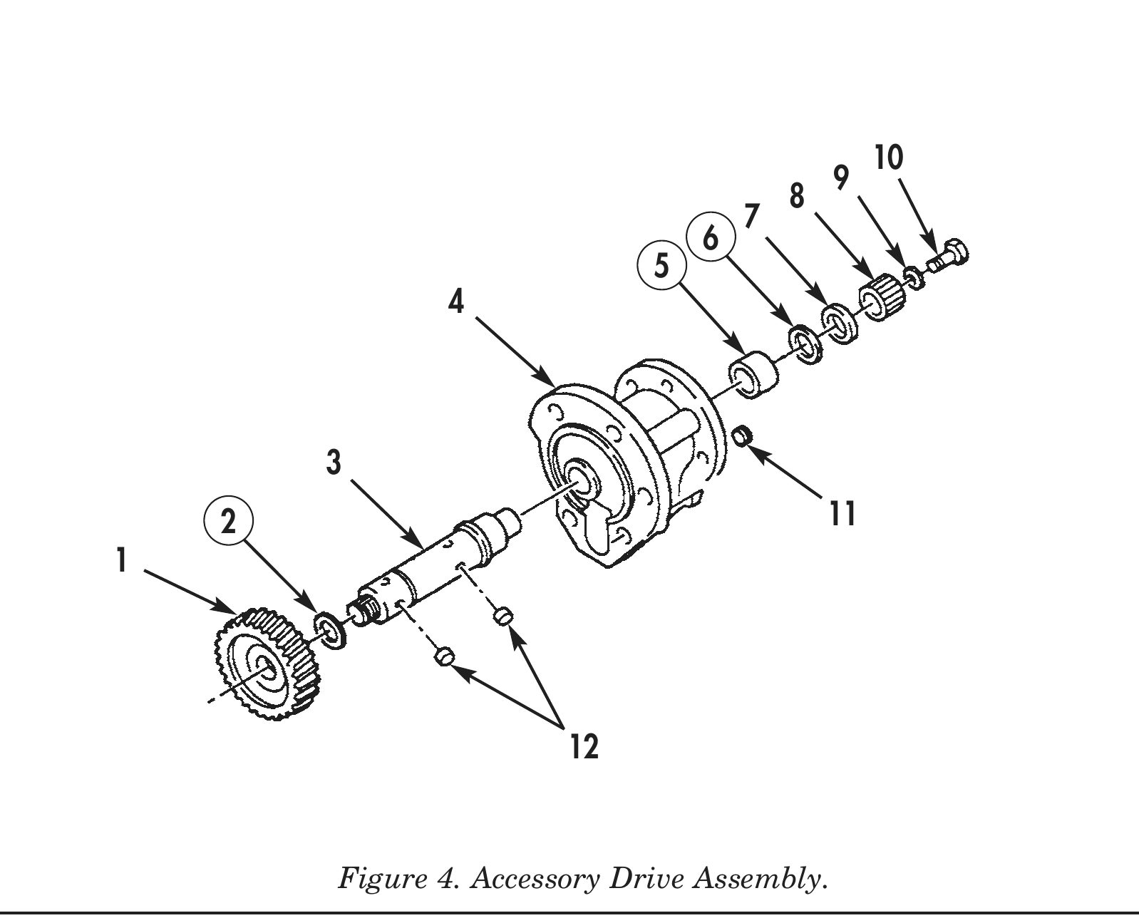
1. Apply pipe sealant to threaded plug (11) and install threaded plug (11) in accessory drive housing (4).
2. Using press and mandrel, install new bushing (5) in accessory drive housing (4).
3. Install two dowel pins (12) in accessory drive shaft (3).
4. Install new thrust bearing (2) on accessory drive shaft (3).
5. Using press and mandrel, install accessory drive gear (1) on accessory drive shaft (3).
6. Install accessory drive shaft (3), with accessory drive gear (1) attached, in accessory drive housing (4).
7. Install new thrust bearing (6) and washer (7) on accessory drive shaft (3).
8. Using press and mandrel, install spline coupling hub (8) on accessory drive shaft (3).
9. Using feeler gauge, measure clearance between accessory drive gear (1) and accessory drive housing (4). Allowable clearance is 0.002–0.012 in. (0.051–0.305 mm).
10. Install washer (9) and screw (10) in accessory drive shaft (3). Tighten screw (10) 30–35 lb-ft (41–48 N•m).
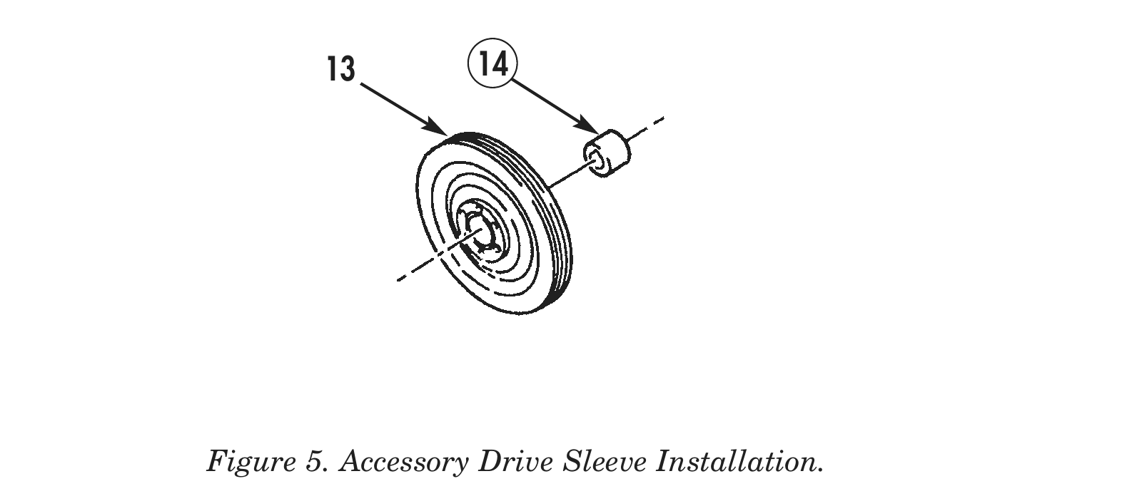
11. Using press and mandrel, install new sleeve (14) in accessory drive pulley (13) 0.015 in. (0.381 mm) below face of accessory drive pulley (13), with chamfered end away from accessory drive pulley (13).
12. For installation of accessory drive and accessory drive pulley, refer to WP 0042 00.