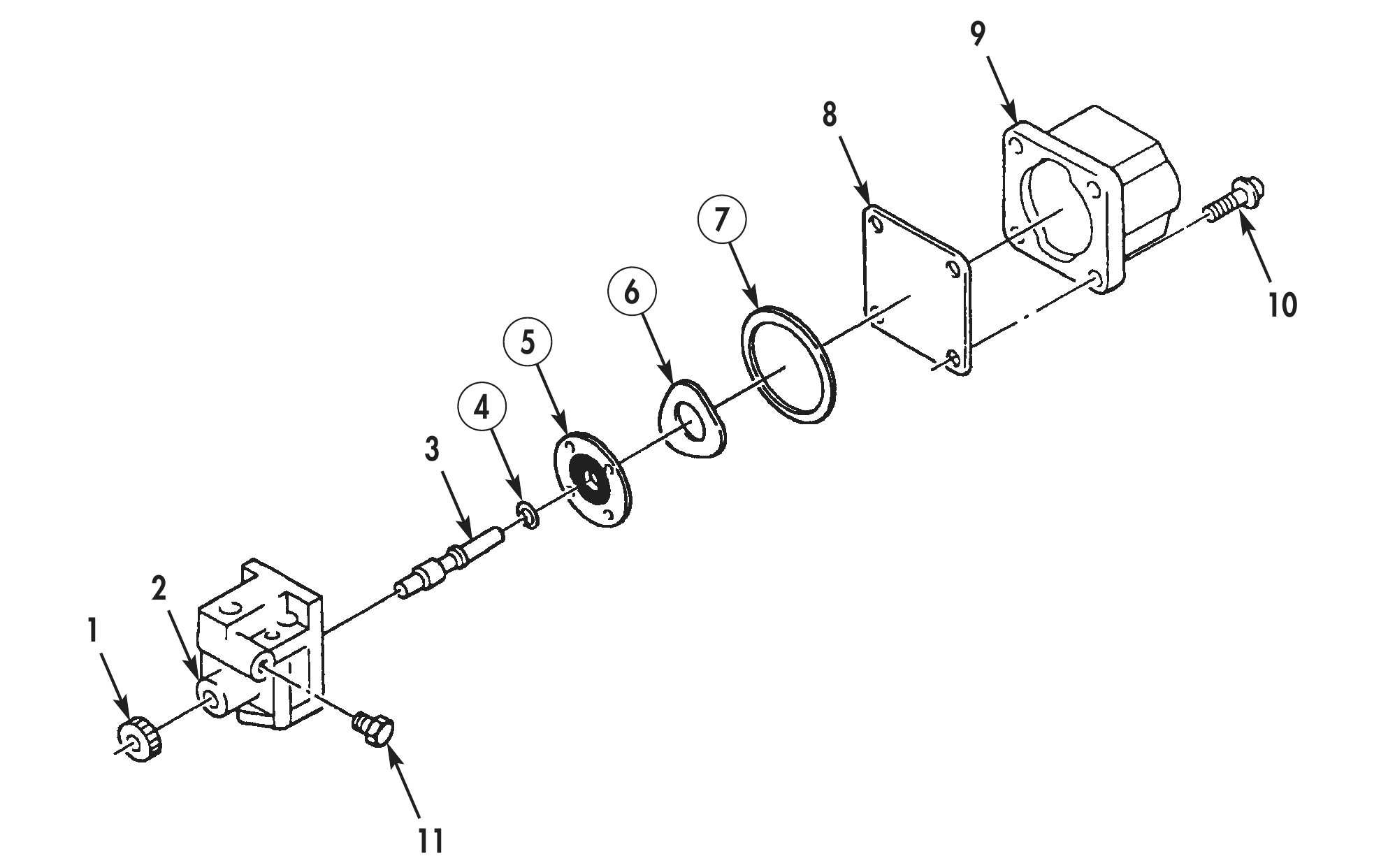
SOLENOID VALVE
TM 9-2815-225-34&P · Work Package 0034 00
DISASSEMBLY, CLEANING AND INSPECTION, ASSEMBLY
INITIAL SETUP
Tools and Special Tools                              Equipment Condition
 General mechanic’s tool kit: automotive              Solenoid valve removed from fuel pump
    (Item 1, WP 0061 00)                                (WP 0033 00).
 Maintenance and repair shop equipment:
    automotive (Item 2, WP 0061 00)
 Automotive maintenance and repair
    supplemental set no. 2 (Item 3, WP 0061 00)

Material/Parts
 Lint-free cloth (Item 6, WP 0060 00)
 Lubricating oil (Item 19, WP 0060 00)
 Rectangular ring seal
   (Item 1, Table 17, WP 0062 00)
 O-ring (Item 2, Table 17, WP 0062 00)
 Shutoff valve spring
   (Item 3, Table 17, WP 0062 00)
 Valve disc (Item 4, Table 17, WP 0062 00)
DISASSEMBLY
1. Remove four screws (10), electrical solenoid (9), shutoff valve shield (8), rectangular ring seal (7), shutoff valve spring (6), and valve disc (5) from valve body (2). Discard rectangular ring seal (7), shutoff valve spring (6), and valve disc (5).
2. Remove shutoff valve knob (1) from shutoff valve shaft (3).
3. Remove shutoff valve shaft (3), with O-ring (4) attached, from valve body (2). Discard O-ring (4).
4. Remove plug (11) from valve body (2).
CLEANING AND INSPECTION
1. For general parts cleaning information, refer to CLEANING, WP 0051 00.
2. For general parts inspection information, refer to INSPECTION, WP 0051 00.
3. Wipe electrical solenoid (9) clean with lint-free cloth.
4. Inspect valve seat on valve body (2) for wear, bonding separation, failure, and corrosion. Discard valve seat if damaged or worn.
5. Using micrometer, measure width of valve seat. Discard valve body (2) if width of valve seat is less than 0.015 in. (0.381 mm).
6. Using multimeter, check electrical solenoid (9) resistance between long terminal and base. Discard electrical solenoid (9) if resistance is not within 28–32 ohms.
ASSEMBLY
1. Apply light coat of lubricating oil to new O-ring (4) and shutoff valve shaft (3), and install O-ring (4) on shutoff valve shaft (3).
2. Turn shutoff valve shaft (3) in valve body (2) until it reaches bottom of bore.
3. Using depth micrometer, position shutoff valve shaft (3) tip 0.118 in. (2.997 mm) from face of valve body (2). Adjust shutoff valve shaft (3) until correct clearance is obtained.
4. Without moving shutoff valve shaft (3), press shutoff valve knob (1) on shutoff valve shaft (3) until fully seated.
5. Install new valve disc (5) in valve body (2) with rubber side toward valve body (2).
6. Apply lubricating oil to new rectangular ring seal (7) and install in valve body (2).
7. Install new shutoff valve shaft spring (6) in valve body (2) with concave side up.
8. Install shutoff valve shield (8) and electrical solenoid (9) on valve body (2) with four screws (10). Tighten screws 25–30 lb-ft (34–40 N•m).
9. Install solenoid valve (WP 0040 00).