CYLINDER BLOCK
TM 9-2815-225-34&P · Work Package 0013 00
DISSASSEMBLY, CLEANING AND INSPECTION, ASSEMBLY
INITIAL SETUP
Tools and Special Tools                              Materials/Parts (Contd)
 General mechanic’s tool kit: automotive              Two expansion plugs
    (Item 1, WP 0061 00)                                (Item 7, Table 1, WP 0062 00)
 Maintenance and repair shop equipment:               Six shims (Item 8, Table 1, WP 0062 00)
    automotive (Item 2, WP 0061 00)
 Automotive maintenance and repair                   Equipment Condition
    supplemental set no. 2 (Item 3, WP 0061 00)       Engine mounted on maintenance stand
 Cylinder sleeve driver (Item 47, WP 0061 00)           (WP 0009 00).
 Cylinder sleeve clamp (Item 48, WP 0061 00)          Cylinder block disassembled (WP 0012 00).
 Gauge block (Item 49, WP 0061 00)
 Engine block counterbore tool
    (Item 50, WP 0061 00)
 Universal cylinder sleeve puller
    (Item 52, WP 0061 00)

Materials/Parts
 Oil, lubricating, OE/HDO 10
   (Item 19, WP 0060 00)
 Cloth, emery, 290-grit (Item 5, WP 0060 00)
 Sealant, pipe (Item 25, WP 0060 00)
 Six gaskets (Item 1, Table 1, WP 0062 00)
 Six black O-rings (Item 2, Table 1, WP 0062 00)
 Six red O-rings
   (Item 3, Table 1, WP 0062 00)
 Four expansion plugs
   (Item 4, Table 1 WP 0062 00)
 Expansion plug (Item 5, Table 1, WP 0062 00)
 Cap (Item 6, Table 1, WP 0062 00)
DISASSEMBLY
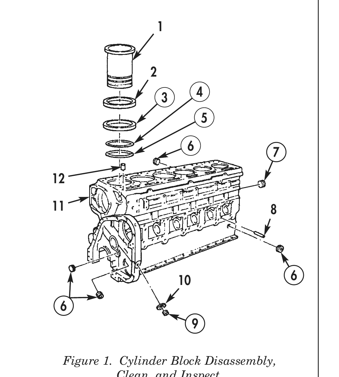
1. Using universal cylinder sleeve puller, remove cylinder sleeve (1) from cylinder block (11).
2. Remove red O-ring (4), black O-ring (5), gasket (3) and shims (2) from cylinder sleeve (1). Discard red O-ring (4), black O-ring (5), and gasket (3).
3. Perform steps 1 and 2 for remaining cylinder sleeves.
4. Remove sixteen expansion plugs (6) from cylinder block (11). Discard expansion plugs (6).
5. Remove expansion plug (9) and washer (10) from cylinder block (11). Discard expansion plug (9).
6. Remove six dowel pins (12) from cylinder block (11).
7. Remove six cam follower dowel pins (8) from cylinder block (11).
8. Using hammer and punch, remove cap (7) from cylinder block (11). Discard cap (7).
CLEANING AND INSPECTION
1. For general parts cleaning information, refer to CLEANING, WP 0051 00.
2. For general parts inspection information, refer to INSPECTION, WP 0051 00.
3. Using crack detector dye, inspect cylinder sleeves (1) and cylinder block (11) for cracks.
4. Inspect cylinder sleeves (1) for excessive corrosion, erosion, and pits. Maximum pit depth is .0625 in. (1.6 mm).
5. Inspect underside top flange of cylinder sleeves (1) for dents, pitting, or worn surfaces. If surface cannot be smoothed out with 290-grit emery cloth, discard cylinder sleeve (1).
6. Using dial bore gauge, measure inside bore of cylinder sleeve (1). Maximum inside diameter is 5.505 in. (13.983 cm).
7. Inspect all cylinder block (11) plug holes and threaded holes for damaged threads and surfaces.
8. Inspect all dowel pins (8) and (12) for cracks or distortion.
9. Using straightedge and 0.02 in. (0.51 mm) feeler gauge, check cylinder block (11) for flatness. If gap between straightedge and cylinder block (10) is more than 0.02 in. (0.51 mm), cylinder block (11) must be milled.
CLEANING AND INSPECTION (Contd)
10. Inspect cylinder liner counterbore of cylinder block (10) for dirty or rough edges.
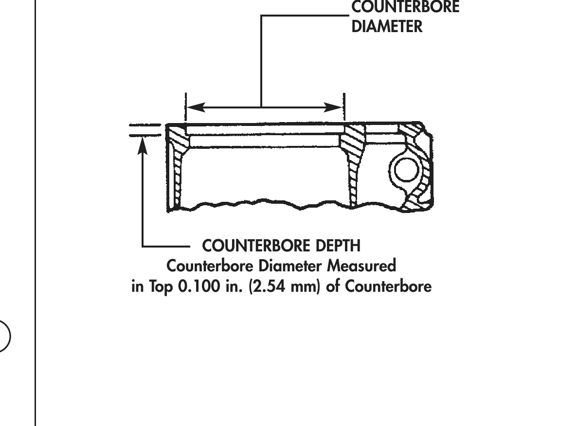
11. Using engine block counterbore tool, measure inside diameter and depth of counterbore at four equally spaced positions. Difference in measurement around circumference must not exceed 0.001 in. (0.0254 mm).
12. Using depth micrometer, measure depth of cylinder sleeve counterbore of cylinder block (11) and outside flange of cylinder sleeve (1) for corresponding cylinder. Subtract difference to determine amount of shims and/or depth of counterbore cut.
COUNTERBORE
3 4 DIAMETER
6 7
11 8
COUNTERBORE DEPTH
Counterbore Diameter Measured in Top 0.100 in. (2.54 mm) of Counterbore
10 6
Figure 1. Cylinder Block Disassembly, Clean, and Inspect.
Figure 2. Cylinder Sleeve Counterbore Measurement.
ASSEMBLY
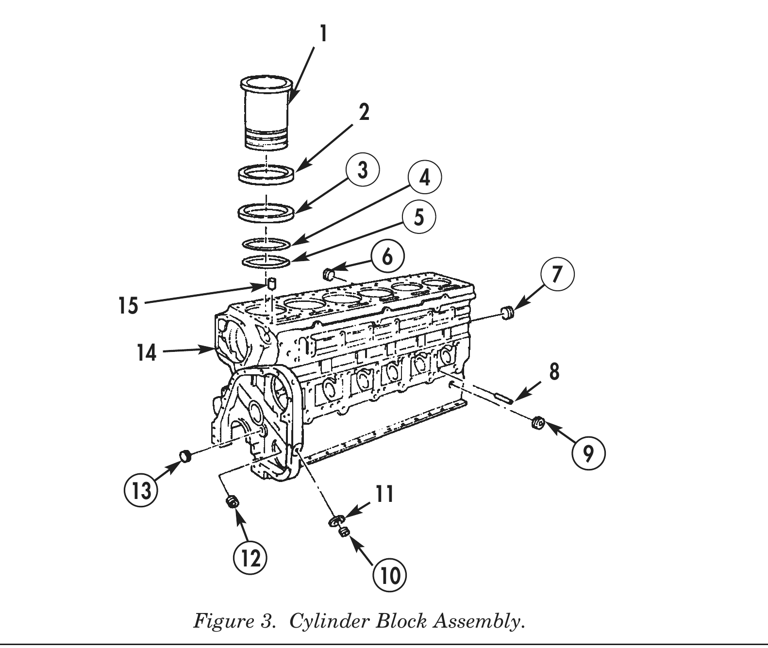
1. Apply pipe sealant to threads of new expansion plug (6). Install expansion plug (6) on cylinder block (14). Tighten plug (6) 30 lb-ft (41 N•m).
2. Apply pipe sealant to threads of two new expansion plugs (12). Install expansion plugs (12) on cylinder block (14). Tighten expansion plugs (12) 45 lb-ft (61 N•m).
3. Apply pipe sealant to threads of four new expansion plugs (9). Install expansion plugs (9) on cylinder block (14). Tighten expansion plugs (9) 15 lb-ft (20 N•m).
4. Apply pipe sealant to threads of five new expansion plugs (13). Install expansion plugs (13) on cylinder block (14). Tighten expansion plugs (13) 35 lb-ft (48 N•m).
5. Apply pipe sealant to threads of new expansion plug (10). Install expansion plug (10) and washer (11) on cylinder block (14). Tighten expansion plug (10) 70 lb-ft (95 N•m).
6. Install cylinder sleeve shims (2), as required, on cylinder sleeve (1).
7. Install new cap (7) on cylinder block (14).
8. Install new gasket (3) with chamfer down in top groove on cylinder sleeve (1).
9. Install new black O-ring (5) on center groove of cylinder sleeve (1).
10. Install new red O-ring (4) on bottom groove of cylinder sleeve (1).
11. Apply OE/HDO 10 lubricating oil to gasket (3) and O-rings (4) and (5) and install assembled cylinder sleeve (1) on cylinder block (15) within 10 minutes.
12. Position cylinder sleeve (1) on bore of cylinder block (14) by hand and push downward with one quick stroke.
13. Using cylinder sleeve driver and mallet, drive flange against counterbore edge.
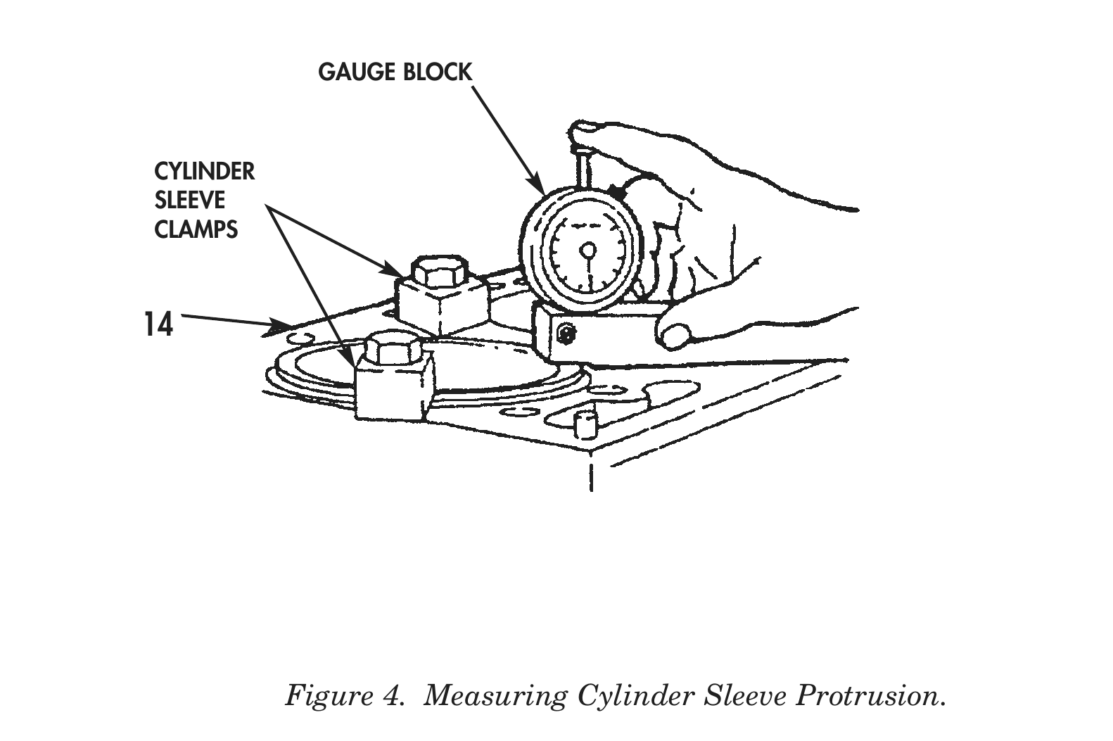
14. Install two cylinder sleeve clamps on cylinder block (14) and cylinder sleeve (1). Tighten clamps 50 lb-ft (68 N•m).
15. Using gauge block, check protrusion of cylinder sleeve (1). Amount of protrusion must not exceed 0.003–0.006 in. (0.076–0.152 mm).
16. Remove cylinder sleeve clamps from cylinder block (14) and cylinder sleeve (1).
17. Repeat steps 7 through 15 for remaining cylinder sleeves.
3 4
13 11
GAUGE BLOCK
CYLINDER
SLEEVE
CLAMPS
END OF WORK PACKAGE