THEORY OF OPERATION
TM 9-2815-225-34&P · Work Package 0003 00
ENGINE FEATURES, ENGINE OIL SYSTEM COMPONENTS AND PIPING, ENGINE OIL MONITORING SYSTEM,
ENGINE RETARDER BRAKE CONTROL, ENGINE SPEED CONTROLS
SCOPE
This Work Package provides you with information regarding theory of operation for the Cummins NTC-400 diesel engine.
ENGINE FEATURES
The Cummins NTC-400 diesel engine is used on all M915 through M920, M915A1, and M915A4 trucks. It is a turbocharged, liquid-cooled, overhead valve, four-cycle engine of in-line, six-cylinder design. The NTC-400 engine has a compression ratio of 13.5:1 (Big Cam I) and 14.0:1 (Big Cam III) and develops 400 horsepower at 2100 rpm. Peak torque is 1150 lb-ft at 1500 rpm (Big Cam I) and 1300 lb-ft at 1300 rpm (Big Cam III). The following engine characteristics and features apply to both Big Cam I and Big Cam III engines, except where differences are noted. Camshaft: 2 1/2-inch diameter camshaft with gear drive controlling all valve and injector movement. Made of induction hardened alloy steel. Camshaft followers are roller-type. Connecting Rods: Drop-forged, rifle-drilled for pressure lubrication. Crankshaft: High-tensile steel forging. Bearing journals and fillets are induction hardened. Fully counterweighted. Cylinder Block: Alloy cast iron with removable wet liners. Cylinder Heads: Each head serves two cylinders. Drilled fuel supply and return lines. High temperature inserts on exhaust valve seats. Turbocharger: Model T-50 (Big Cam I); Model T-46-B (Big Cam III) has a redesigned compressor wheel, compressor housing, turbine wheel and shaft, bearing housing assembly, location of oil inlet line, and V-bands. Exhaust Manifold: Conventional log-type (Big Cam I). Pulse-type for less restriction (Big Cam III). Fuel System: Integral flywheel-type governor. Injectors: Camshaft actuated top stop-type. Intake Manifold: Conventional aftercooler (Big Cam I); triple-pass water aftercooler (Big Cam III). Lubrication Oil Cooler: Conventional oil cooler and filter with separately mounted bypass oil filter on engine firewall (Big Cam I). Demand flow automatically regulates oil pressure and routes engine coolant through engine oil cooler twice. Engine and cooler cores are made of cast aluminum and incorporate mounting adapters for spin-on-type full-flow and bypass oil filters; also incorporate a bypass valve and pressure sending unit (Big Cam III). Oil Pan: Made of cast aluminum (Big Cam I). Made of stamped steel (Big Cam III). Water Transfer Tube: Made of cast iron (Big Cam I). Made of stamped, welded steel (Big Cam III).
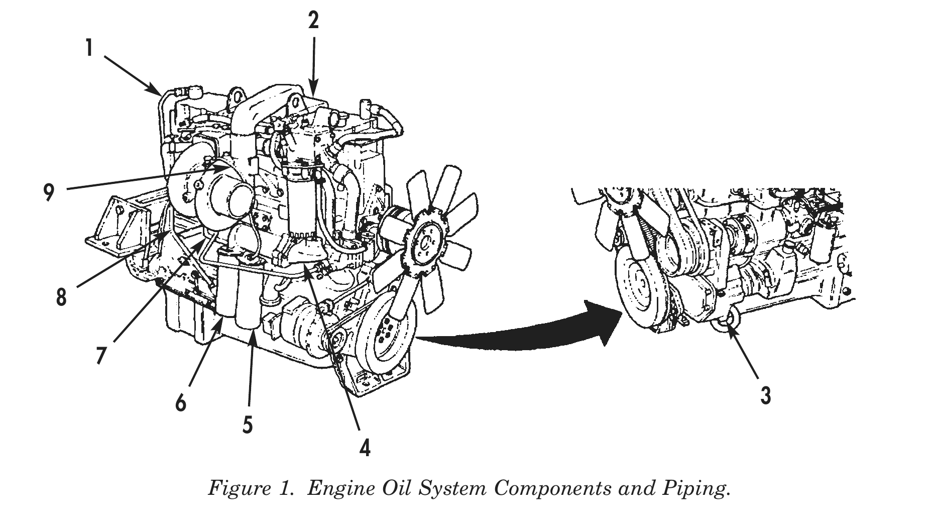
ENGINE OIL SYSTEM COMPONENTS AND PIPING
Breather Tube (1) – Allows fumes from hot oil to escape. Oil Filler (2) – Located in front rocker arm cover. Used for replenishing oil supply. Oil Pump (3) – Circulates oil through engine to provide cooling and lubrication. Oil Cooler (4) – Coolant circulates through internal tubes of cooler and carries away heat from engine oil. Primary Oil Filter (5) – Throwaway filter removes dirt and foreign particles from oil. Bypass Oil Filter (6) – Throwaway filter provides filtration when primary filter is clogged or damaged. Oil Return Line (7) – Carries return oil from turbocharger to engine block. Oil Level Dipstick (8) – Indicates engine oil level. Oil Supply Line (9) – Carries oil under pressure to cool and lubricate turbocharger.
6 3 Figure 1. Engine Oil System Components and Piping.
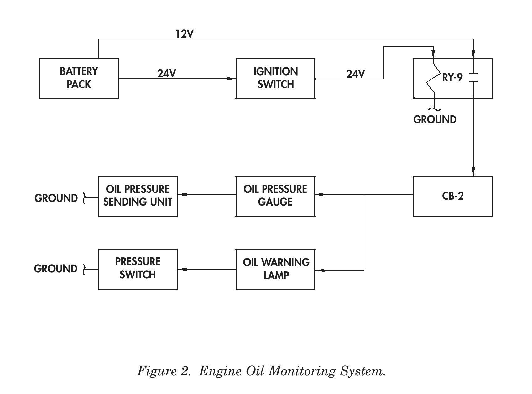
ENGINE OIL MONITORING SYSTEM
Battery Pack – Consists of four 12-volt, maintenance-free batteries. Two batteries are wired in parallel in each set. Each set is connected in series for 24-volt output. Battery pack is used for both 12-volt and 24-volt output. Ignition Switch – Supplies 24-volt power to relay (RY-9), which in turn provides 12-volt power to electrical system, including oil pressure gauge and warning lamp circuits. Relay (RY-9) – Energized by 24-volt power from ignition switch. When energized, RY-9 supplies 12-volt power to circuit breaker (CB-2). Circuit Breaker (CB-2) – Protects electrical components of oil system by opening circuit when load exceeds 20 amperes. May be manually reset by pressing CB-2 button in. Oil Pressure Gauge – Activated by electrical signal from oil pressure sending unit. Indicates engine oil pressure. Oil Pressure Sending Unit – Provides electrical signal to oil pressure gauge to indicate engine oil pressure. Oil Warning Lamp – Indicator lamp is activated by 12-volt power from pressure switch when engine oil pressure drops below 5 psi. Pressure Switch – Closes to supply 12-volt power to oil warning lamp when oil pressure drops below 5 psi.
12V
BATTERY 24V IGNITION 24V RY-9
PACK                                   SWITCH
GROUND
OIL PRESSURE               OIL PRESSURE
GROUND                                                                CB-2
SENDING UNIT                  GAUGE
PRESSURE                 OIL WARNING
GROUND
SWITCH                      LAMP
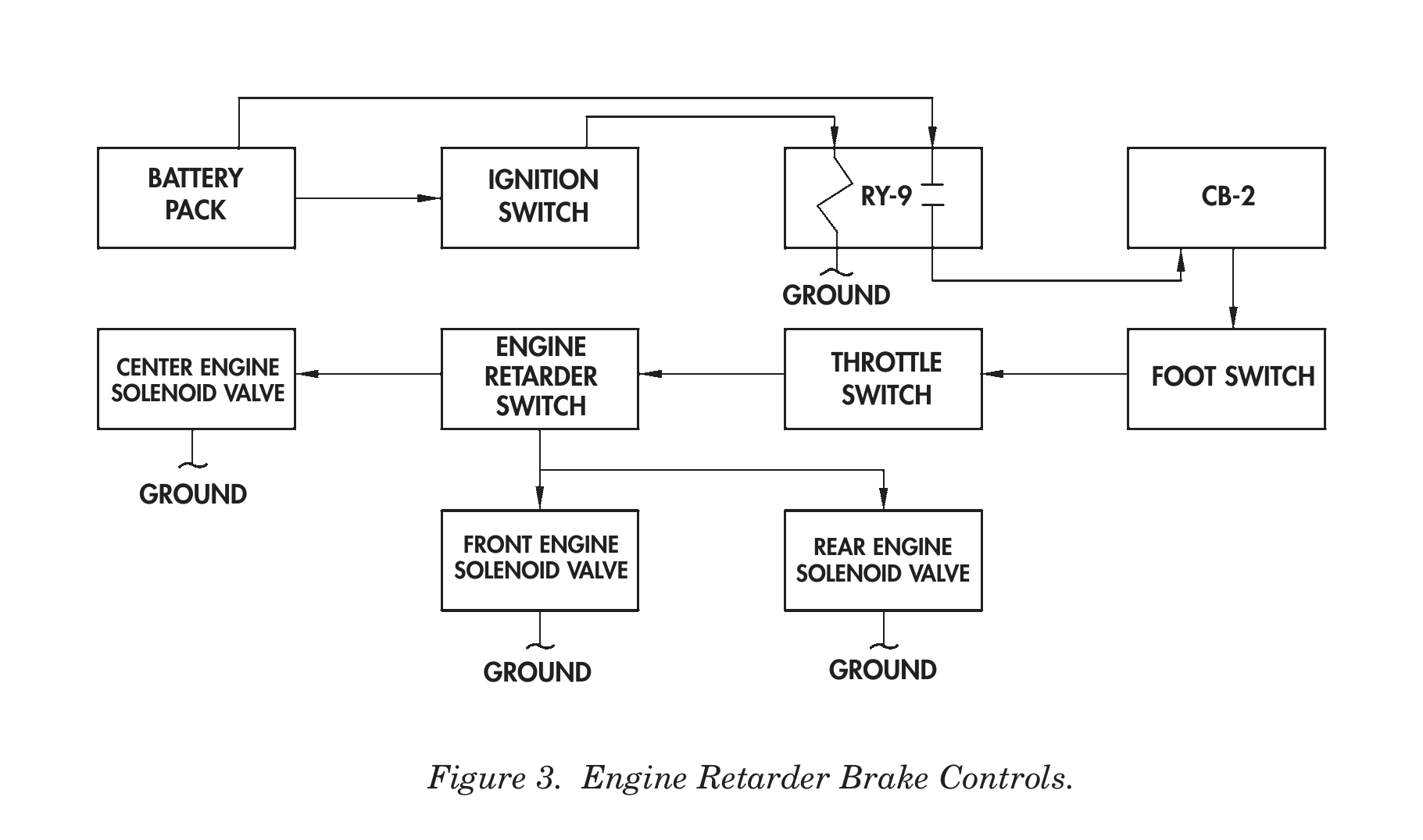
ENGINE RETARDER BRAKE CONTROL
Battery Pack – Consists of four 12-volt, maintenance-free batteries. Two batteries are wired in parallel in each set. Each set is connected in series for 24-volt output. Battery pack is used for both 12-volt and 24-volt output. Ignition Switch – Supplies 24-volt power to relay (RY-9), which in turn provides 12-volt power to electrical system, including engine retarder brake circuit. Relay (RY-9) – Energized by 24-volt power from ignition switch. When energized, RY-9 supplies 12-volt power to circuit breaker (CB-2). Circuit Breaker (CB-2) – Protects electrical components of engine retarder brake circuit by opening when load exceeds 20 amperes. May be manually reset by pressing CB-2 button in. Foot Switch – Allows driver to activate engine brake circuit with left foot. When depressed, switch supplies 12-volt power through CB-2, throttle switch, and engine retarder switch to energize selected solenoid valve(s). Throttle Switch – Switch is open when accelerator pedal is pressed down to prevent activation of engine retarder brake. Activating arm on fuel pump lever closes switch when accelerator is disengaged. Engine Retarder Switch – Three-position switch allows driver to select engine braking for two cylinders (LOW), four cylinders (MED), or six cylinders (HIGH). Depressing pedal-actuated foot switch completes 12-volt power circuit to energize one, two, or three solenoids. Solenoid Valves – Operate engine braking mechanism when activated.
BATTERY                IGNITION
RY-9                CB-2
PACK                   SWITCH
GROUND
ENGINE
CENTER ENGINE                                       THROTTLE
RETARDER                                     FOOT SWITCH
SOLENOID VALVE                                       SWITCH
SWITCH
GROUND
FRONT ENGINE            REAR ENGINE
SOLENOID VALVE          SOLENOID VALVE
GROUND                     GROUND
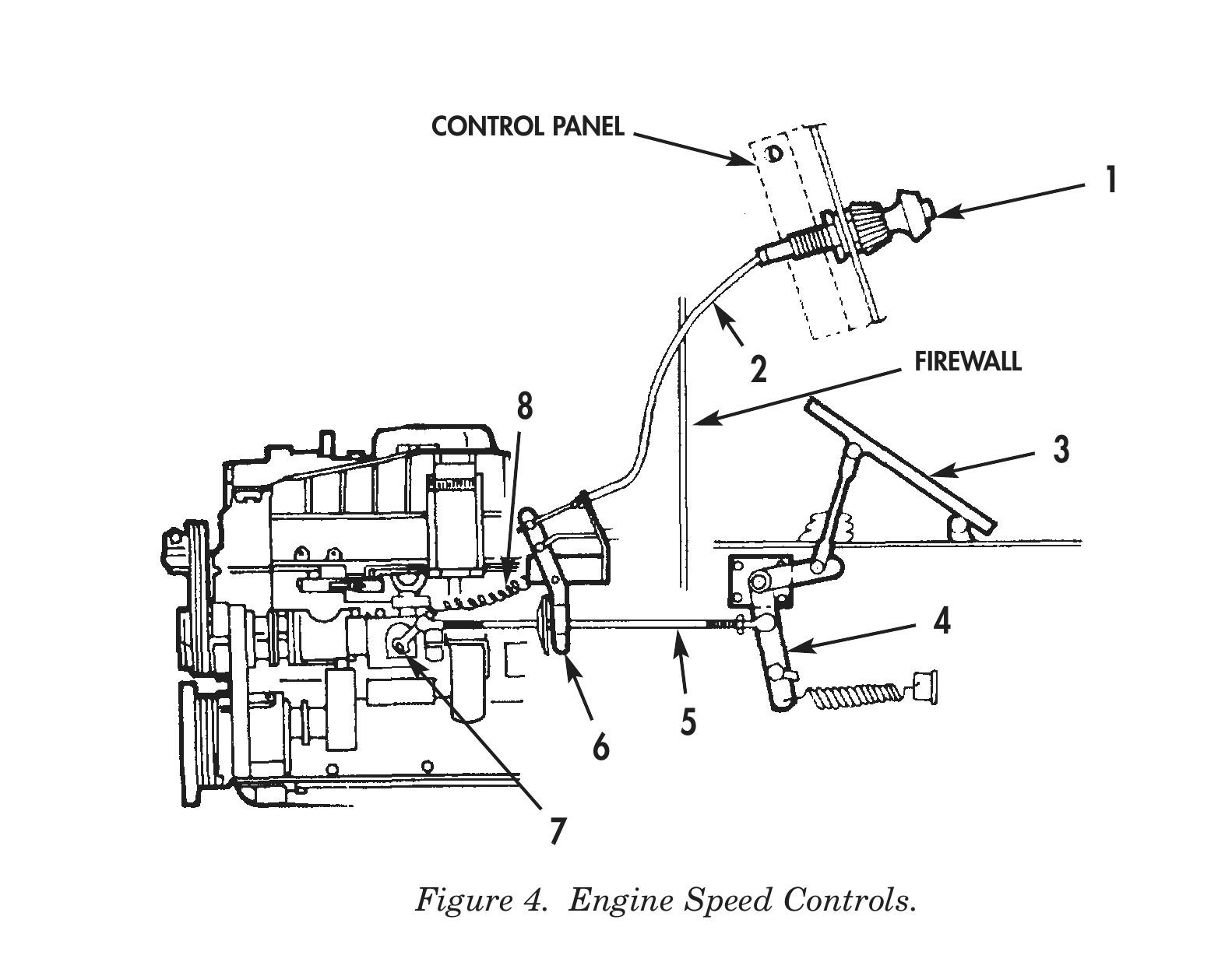
ENGINE SPEED CONTROLS
Hand Throttle (1) – Allows manual control of engine rpm. Throttle motion is transferred by cable to engine mounted pivot lever (6). Throttle Cable (2) – Flex cable from hand throttle to engine-mounted pivot lever (6). Accelerator Pedal (3) – Connected by mechanical linkage to under-cab pivot lever (4). Pivot Lever (4) – Mechanical linkage that connects accelerator pedal to accelerator rod. Accelerator Rod (5) – Connects accelerator pedal and throttle linkage to accelerator lever on fuel pump. Engine Mounted Pivot Lever (6) – Connects under-dash hand throttle cable (ALL) and winch throttle cable (M916 and M920) to accelerator rod. Accelerator Lever (7) – Controls flow of fuel through fuel pump, setting engine speed. Fuel Control Return Spring (8) – Returns accelerator lever to normal position when hand throttle and accelerator pedal are not engaged.
CONTROL PANEL
2      FIREWALL
END OF WORK PACKAGE
TROUBLESHOOTING PROCEDURES
FOR
ENGINE, DIESEL
CUMMINS MODEL NTC-400
M915, M915A1, M915A4,
M916, M920 VEHICLES
Work Package Title Work Package/Page No.
Engine Troubleshooting . . . . . . . . . . . . . . . . . . . . . . . . . . . . . . WP 0004 00-1