CRANKSHAFT CLEANING AND INSPECTION
TM 9-2815-225-34&P · Work Package 0016 00
INITIAL SETUP
Tools and Special Tools
 General mechanic’s tool kit: automotive
    (Item 1, WP 0061 00)
 Maintenance and repair shop equipment,
    automotive (Item 2, WP 0061 00)
 Automotive maintenance and repair
    supplemental set no. 2 (Item 3, WP 0061 00)

Equipment Condition
 Engine crankshaft and main bearings removed
   (WP 0012 00).
1. For general parts cleaning information, refer to CLEANING, WP 0051 00.
2. For general parts inspection information, refer to INSPECTION, WP 0051 00.
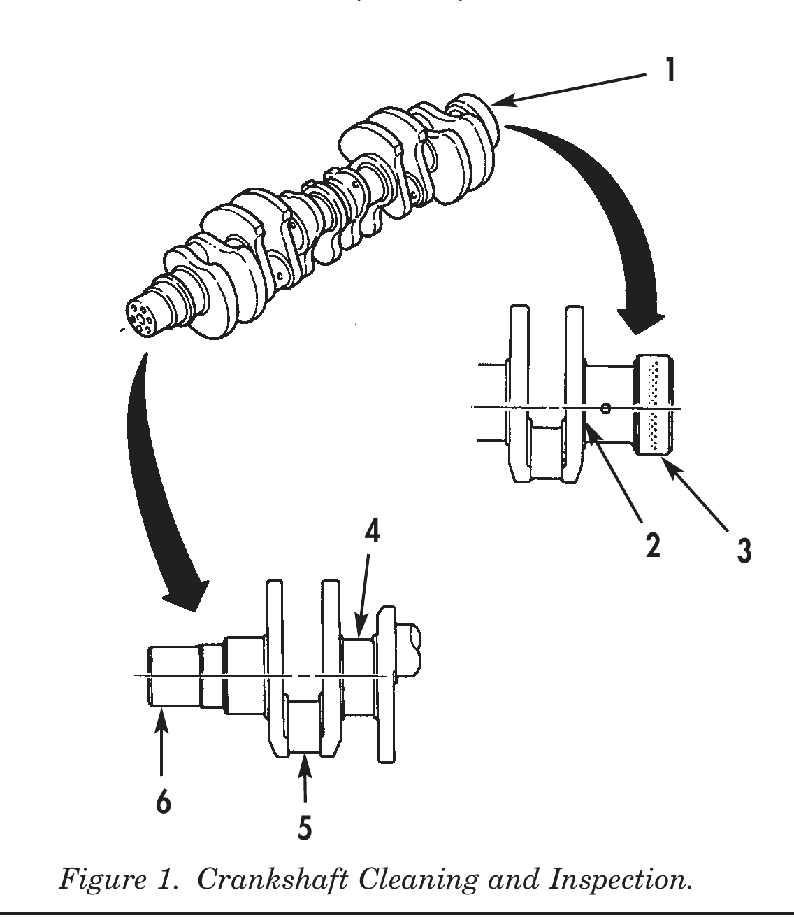
3. Inspect crankshaft (1) for cracks, breaks, damage, or wear.
4. Inspect rear oil seal contact area (3) for wear and grooves.
5. Using vernier caliper, measure outside diameter of rear oil seal contact area (3). Minimum diameter is 5.998 in. (15.234 cm).
6. Inspect front oil seal contact area (6) for wear and grooves.
7. Using vernier caliper, measure outside diameter of front oil seal contact area (6). Minimum diameter is 3.625 in. (9.207 cm).
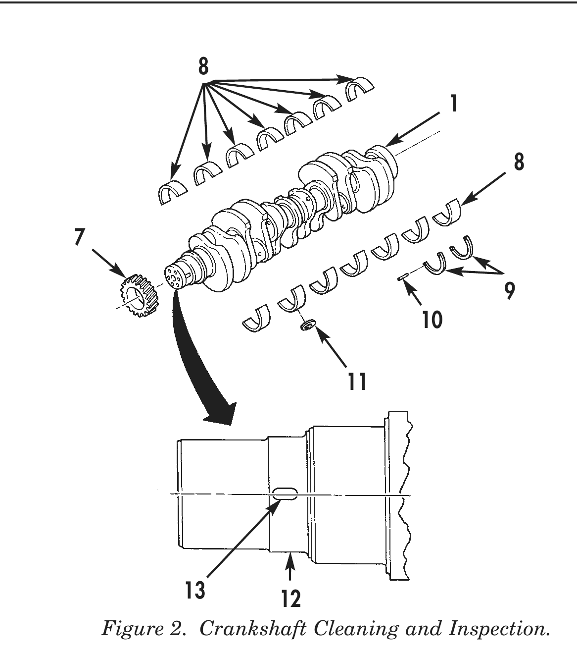
8. Inspect main bearing halves (8) for pits, scratches, or grooves.
9. Using micrometer, measure thickness of main bearing halves (8). Minimum thickness is 0.123 in. (3.124 mm). Maximum thickness is 0.1238 in. (3.144 mm). Wear limit is 0.1215 in. (3.0861 mm).
10. Using vernier caliper, measure rod bearing journal (5) diameter at three and six o’clock positions. Minimum diameter is 3.124 in. (7.933 cm).
11. Using vernier caliper, measure main bearing journal (4) diameter. Minimum diameter is 4.489 in. (11.426 cm).
12. Measure thickness of each thrust ring (9) at different locations. Minimum thrust ring (9) thickness is 0.245 in. (6.223 mm). If endplay clearance exceeds 0.022 in. (0.559 mm), install oversize thrust rings.
13. Inspect two thrust ring pins (10) for damage or wear.
14. Inspect seven retaining rings (11) for wear, out-of-round, or cracks.
15. Inspect crankshaft gear (7) for worn, cracked, or broken gear teeth.
16. Inspect crankshaft gear (7) for loose or worn keyway.
17. Inspect crankshaft keyway (13) for looseness, wear, or damage.
18. Using vernier caliper, measure width of keyway (13). Maximum width is 0.375 in. (9.525 mm).
19. Inspect crankshaft gear step (12) for wear, grooves, or damage.
20. Using vernier caliper, measure outside diameter of crankshaft gear step (12). Minimum diameter is 3.761 in. (9.552 cm).
21. Using vernier caliper, measure crankshaft thrust flange (4). Wear greater than 0.003 in. (0.076 mm) requires regrinding to restore flatness.
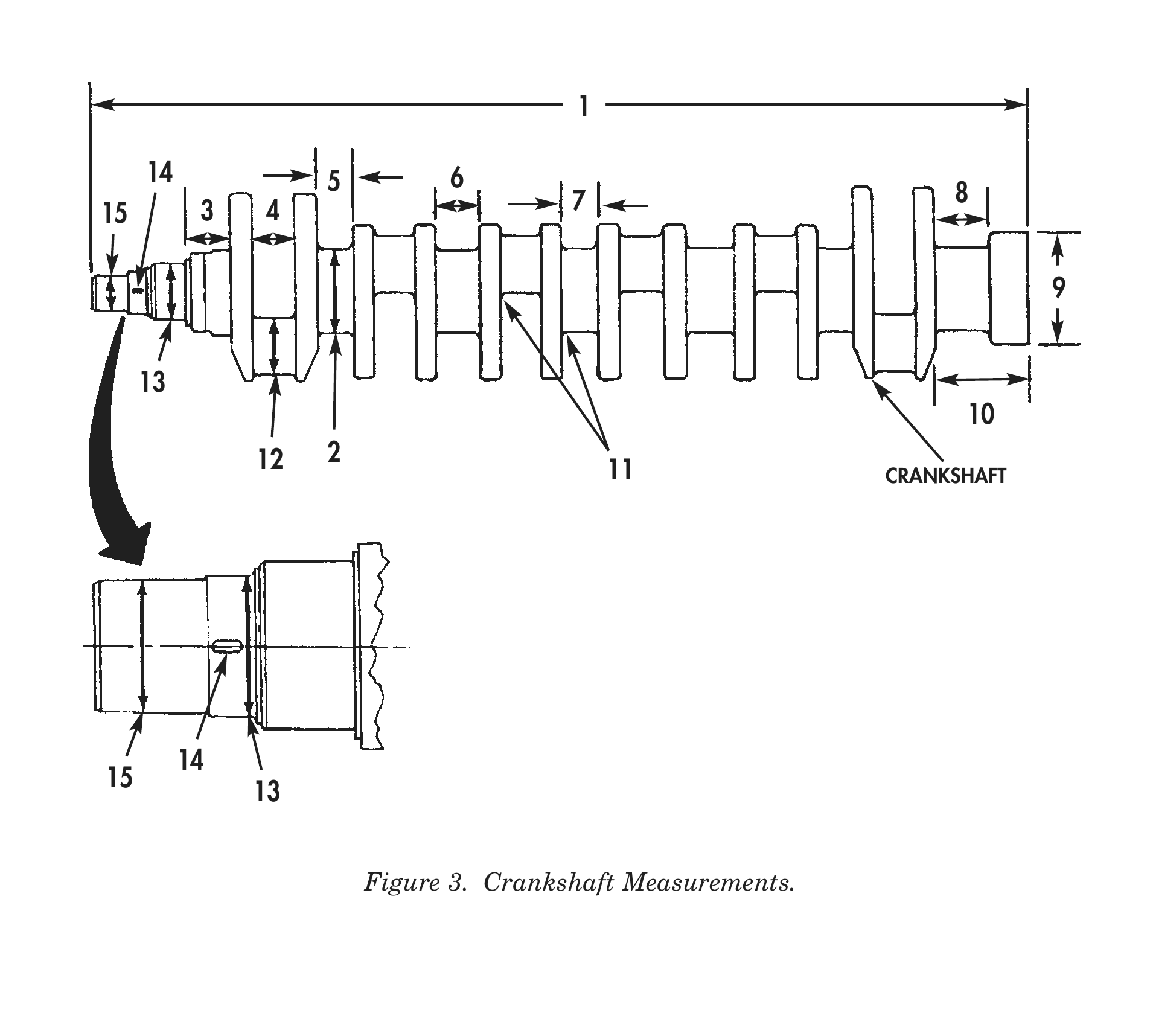
22. Using vernier caliper and micrometer, measure crankshaft dimensions shown in Figure 3. Compare measurements to specifications in Table 1. Wear greater than 0.002 in. (0.051 mm), or greater than 0.003 in. (0.076 mm) for item 8, requires regrinding.
Table 1. Crankshaft Dimensions and Points of Measurements. 1 51.813 in. (131.604 mm) 2 4.497–4.500 in. (11.426–11.43 cm) 3 2.438 in. (6.191 cm) 4 2.126–2.128 in. (5.40–5.405 cm) 5 2.00 in. (5.08 cm) 6 2.50 in. (6.35 cm) 7 2.00 in. (5.08 cm) 8 3.001–3.003 in. (7.622–7.628 cm) 9 5.998–6.000 in. (15.234–15.24 cm) 10 5.151–5.163 in. (13.083–13.114 cm) 11 0.173–0.196 in. (7.933–7.937 cm) 12 3.124–3.125 in. (4.389–4.973 cm) 13 3.761 in. (9.552 cm) 14 0.375 in. (0.953 mm) 15 3.625–3.626 in. (9.207–9.300 cm)
FLEXPLATE, FLYWHEEL, FLYWHEEL HOUSING,
AND REAR COVER CLEANING AND INSPECTION
INITIAL SETUP
Tools and Special Tools
 General mechanic’s tool kit:
    automotive (Item 1, WP 0061 00)
 Maintenance and repair shop equipment:
    automotive (Item 2, WP 0061 00)
 Automotive maintenance and repair
    supplemental set no. 2 (Item 3, WP 0061 00)
 Magnetic crack detector (Item 5, WP 0061 00)

Equipment Condition
 Flexplate, flywheel, flywheel housing, and rear
   cover removed from engine (WP 0012 00).