FUEL PUMP ASSEMBLY
TM 9-2815-225-34&P · Work Package 0040 00
FUEL PUMP FRONT COVER AND GOVERNOR, FUEL PUMP GOVERNOR SPRING, FUEL GEAR PUMP, FUEL
DAMPER AND HEAD, SOLENOID VALVE
INITIAL SETUP
Tools and Special Tools                             Material/Parts (Contd)
 General mechanic’s tool kit: automotive             Gasket (Item 10, Table 23, WP 0062 00)
    (Item 1, WP 0061 00)                             Plastic bushing seal
 Maintenance and repair shop equipment:                (Item 11, Table 23, WP 0062 00)
    automotive (Item 2, WP 0061 00)                  Lubricating oil (Item 19, WP 0060 00)
 Automotive maintenance and repair
    supplemental set no. 2 (Item 3, WP 0061 00)     Equipment Condition
 Ball joint vise (Item 9, WP 0061 00)                Fuel pump removed from engine
 Fuel pump mounting plate                              (WP 0010 00)
    (Item 10, WP 0061 00)

Material/Parts
 Gasket (Item 1, Table 23, WP 0062 00)
 Two lockwashers
   (Item 2, Table 23, WP 0062 00)
 Four lockwashers
   (Item 3, Table 23, WP 0062 00)
 Four lockwashers
   (Item 4, Table 23, WP 0062 00)
 Two rectangular seals
   (Item 5, Table 23, WP 0062 00)
 Rectangular ring seal
   (Item 6, Table 23, WP 0062 00)
 Eight lockwashers
   (Item 7, Table 23, WP 0062 00)
 Gasket (Item 8, Table 23, WP 0062 00)
 Adjusting screw seal
   (Item 9, Table 23, WP 0062 00)
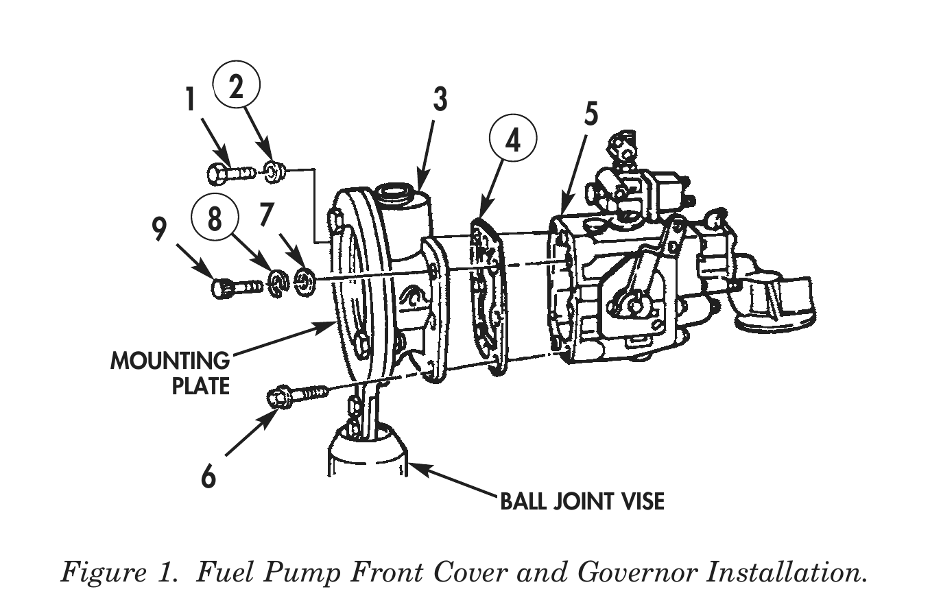
FUEL PUMP FRONT COVER AND GOVERNOR
1. Remove fuel pump front cover (3) from mounting plate and ball joint vise.
2. Install new gasket (4), fuel pump (5), and screw (6) on fuel pump front cover (3). Tighten screws (6) 9–11 lb-ft (12–15 N•m).
3. Install six washers (7), eight new lockwashers (8), and screws (9) securing fuel pump front cover (3) on fuel pump (5). Tighten screw (9) 9–11 lb-ft (12–15 N•m).
4. Install new plastic bushing seal (2) and screw (1) on fuel pump front cover (3). Tighten screw (1) 9–11 lb-ft (12–15 N•m).
5. For fuel pump front cover and governor repair, refer to WP 0038 00.
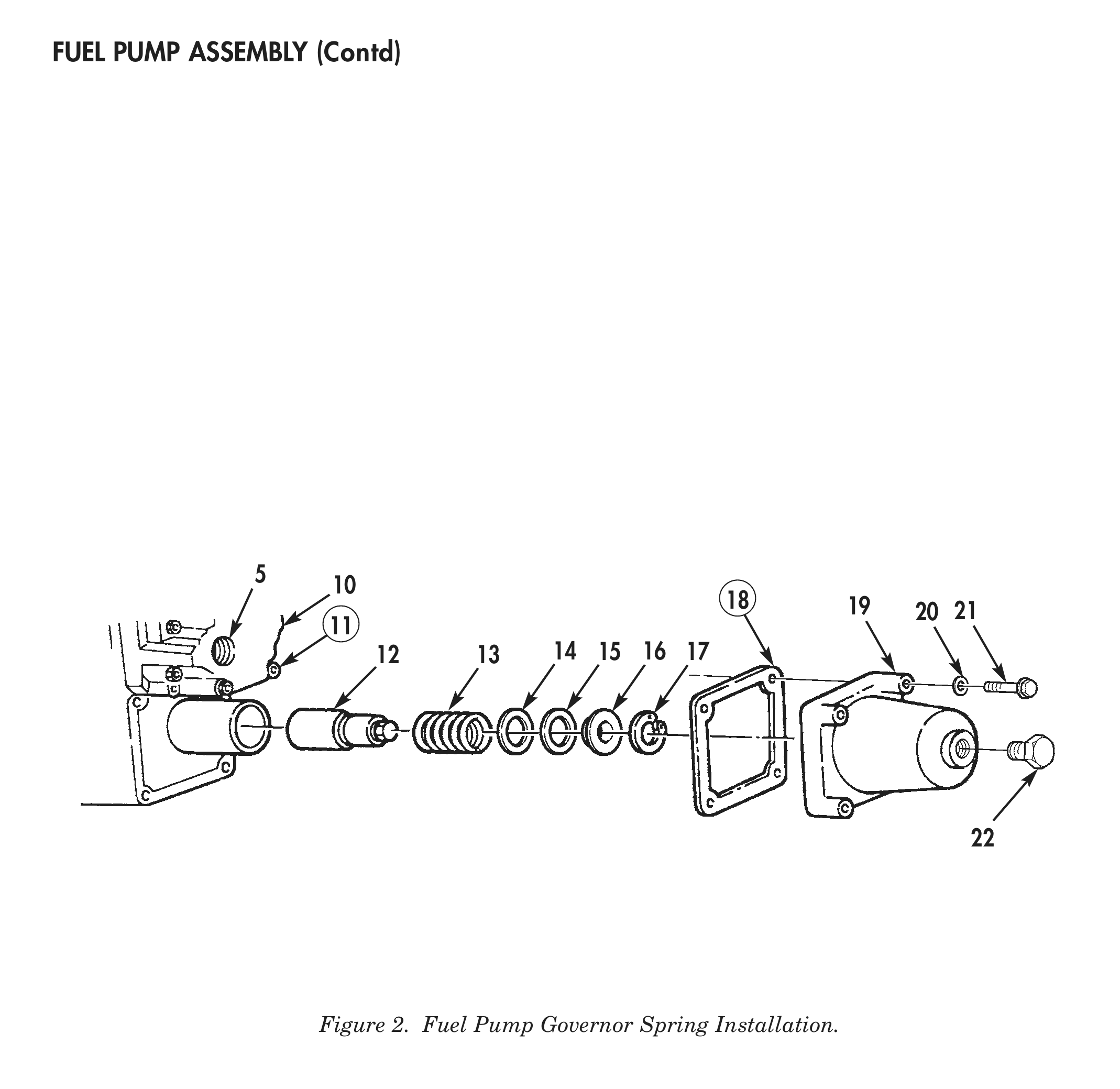
FUEL PUMP GOVERNOR SPRING
1. Install fuel pump governor spring (13), snapring (17), shims (14) and (15) and spring seat (16), on guide (12).
2. Install new gasket (18), spring pack cover (19), four washers (20), and screws (21) on fuel pump (5). Place screw (21) with lockwire hole in upper right corner of spring pack cover (19). Torque screws (21) 9–11 lb-ft (12–15 N•m).
3. Install new adjusting screw seal (11) and wire (10) on cover plug (22).
4. For fuel pump governor spring repair, refer to WP 0037 00.
    1 2              3            5
                           4

9    8    7
MOUNTING
PLATE
BALL JOINT VISE
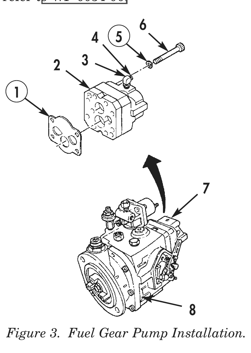
FUEL GEAR PUMP
1. Install fuel supply elbow (3) and adapter (4) on gear body (2).
2. Position notch in upper right-hand corner and install fuel gear pump (7) and new gasket (1) on fuel pump (8). Secure with four screws (6) and new lockwashers (5). Tighten screws (6) 11–13 lb-ft (15–18 N•m).
3. For fuel gear pump repair, refer to WP 0036 00.
FUEL DAMPER AND HEAD
1. Apply light coat of lubricating oil on new rectangular seals (9) and (14) on filter head (10).
2. Install filter head (10) on fuel pump (8) and secure with four screws (13), new lockwashers (12), and washers (11). Tighten screws (13) 11–13 lb-ft (15–18 N•m).
3. For fuel damper and head repair, refer to WP 0035 00.
SOLENOID VALVE
1. Apply light coat of lubricating oil on new rectangular ring seal (21) on solenoid valve (20).
2. Install solenoid valve (20) on fuel pump (8) and secure with two screws (18), new lockwashers (17), and washers (19).
3. Install plug (16) on valve body (15).
4. For solenoid valve repair, refer to WP 0034 00.
4 5 2 3
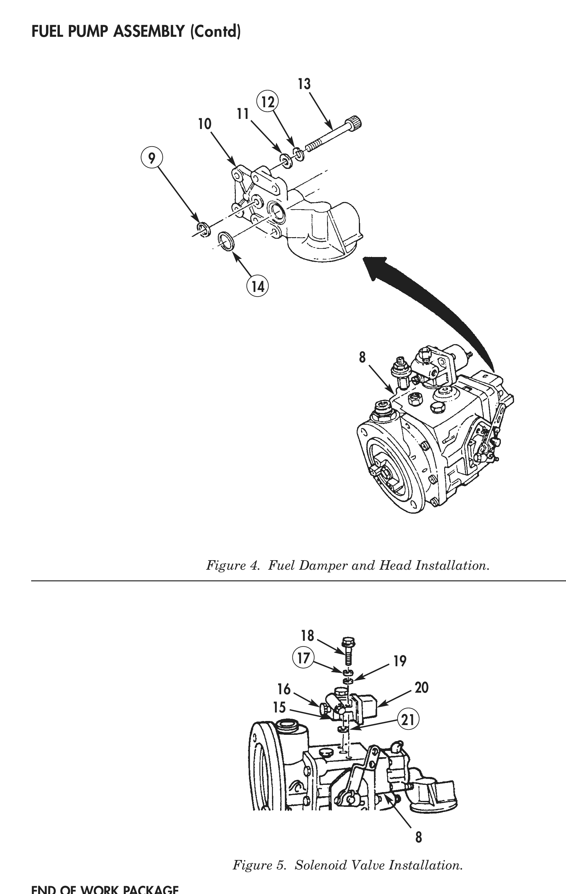
Figure 4. Fuel Damper and Head Installation.
Figure 5. Solenoid Valve Installation.