CYLINDER BLOCK COMPONENTS INSTALLATION
TM 9-2815-225-34&P · Work Package 0042 00
CRANKSHAFT AND MAIN BEARINGS; CAMSHAFT; PISTONS AND CONNECTING RODS;
ACCESSORY DRIVE HOUSING; OIL PUMP; ACCESSORY DRIVE PULLEY;
AIR COMPRESSOR; FRONT GEAR COVER; FLYWHEEL, FLEXPLATE, AND FLYWHEEL HOUSING; OIL PAN
INITIAL SETUP
Tools and Special Tools                                    Material/Parts (Contd)
 General mechanic’s tool kit: automotive                   Cam follower housing gasket
    (Item 1, WP 0061 00)                                     (Item 14, Table 25, WP 0062 00)
 Maintenance and repair shop equipment:                    Eighteen lockwashers
    automotive (Item 2, WP 0061 00)                          (Item 15, Table 25, WP 0062 00)
 Automotive maintenance and repair supplemental            High-pressure lubricating oil (Item 15, WP 0060 00)
    set no. 2 (Item 3, WP 0061 00)                         Gasket (Item 16, Table 25, WP 0062 00)
 Lifting strap                                             Gasket (Item 17, Table 25, WP 0062 00)
 Prybar                                                    Twelve connecting rod bearing halves
 Four camshaft pilot tools (Item 62, WP 0061 00)             (Item 18, Table 25, WP 0062 00)
 Piston ring expander (Item 28, WP 0061 00)                Locknut (Item 19, Table 25, WP 0062 00)
 Pulley installation assembly tool                         Lubricating oil OHE/HDO 30 (Item 20, WP 0060 00)
    (Item 63, WP 0061 00)                                  Keyway seal (Item 20, Table 25, WP 0062 00)
 Crankshaft seal driver (Item 64, WP 0061 00)              Gasket (Item 21, Table 25, WP 0062 00)
 Piston ring compressor (Item 65, WP 0061 00)              60-80 lubricating oil (Item 21, WP 0060 00)
                                                           Fourteen lockplates (Item 22, Table 25, WP 0062 00)
Material/Parts                                             Lockwasher (Item 23, Table 25, WP 0062 00)
                                                           Three lockwashers (Item 24, Table 25, WP 0062 00)
 Gasket (Item 1, Table 25, WP 0062 00)                     Eleven O-rings (Item 25, Table 25, WP 0062 00)
 Twelve compression rings                                  Pipe sealant (Item 25, WP 0060 00)
    (Item 2, Table 25, WP 0062 00)                         Nine lockwashers (Item 26, Table 25, WP 0062 00)
 Gasket (Item 3, Table 25, WP 0062 00)                     Thirteen lockwashers
 Four lockwashers (Item 4, Table 25, WP 0062 00)             (Item 27, Table 25, WP 0062 00)
 Twelve compression rings                                  Two lockwashers (Item 28, Table 25, WP 0062 00)
    (Item 5, Table 25, WP 0062 00)                         Gasket (Item 29, Table 25, WP 0062 00)
 Six piston rings (Item 6, Table 25, WP 0062 00)           Four lockwashers (Item 30, Table 25, WP 0062 00)
 Rear main seal (Item 7, Table 25, WP 0062 00)             Two O-rings (Item 31, Table 25, WP 0062 00)
 Four thrust bearing washers                               Gasket (Item 32, Table 25, WP 0062 00)
    (Item 8, Table 25, WP 0062 00)
 Six piston rings (Item 9, Table 25, WP 0062 00)
 Gasket (Item 10, Table 25, WP 0062 00)                  Personnel Required
 Seal (Item 11, Table 25, WP 0062 00)                      One assistant
 O-ring (Item 12, Table 25, WP 0062 00)
 GAA grease (Item 13, WP 0060 00)                        Equipment Condition
 Fourteen main bearing halves                              Engine mounted on maintenance stand
    (Item 13, Table 25, WP 0062 00)                          (WP 0009 00)
CRANKSHAFT AND MAIN BEARINGS
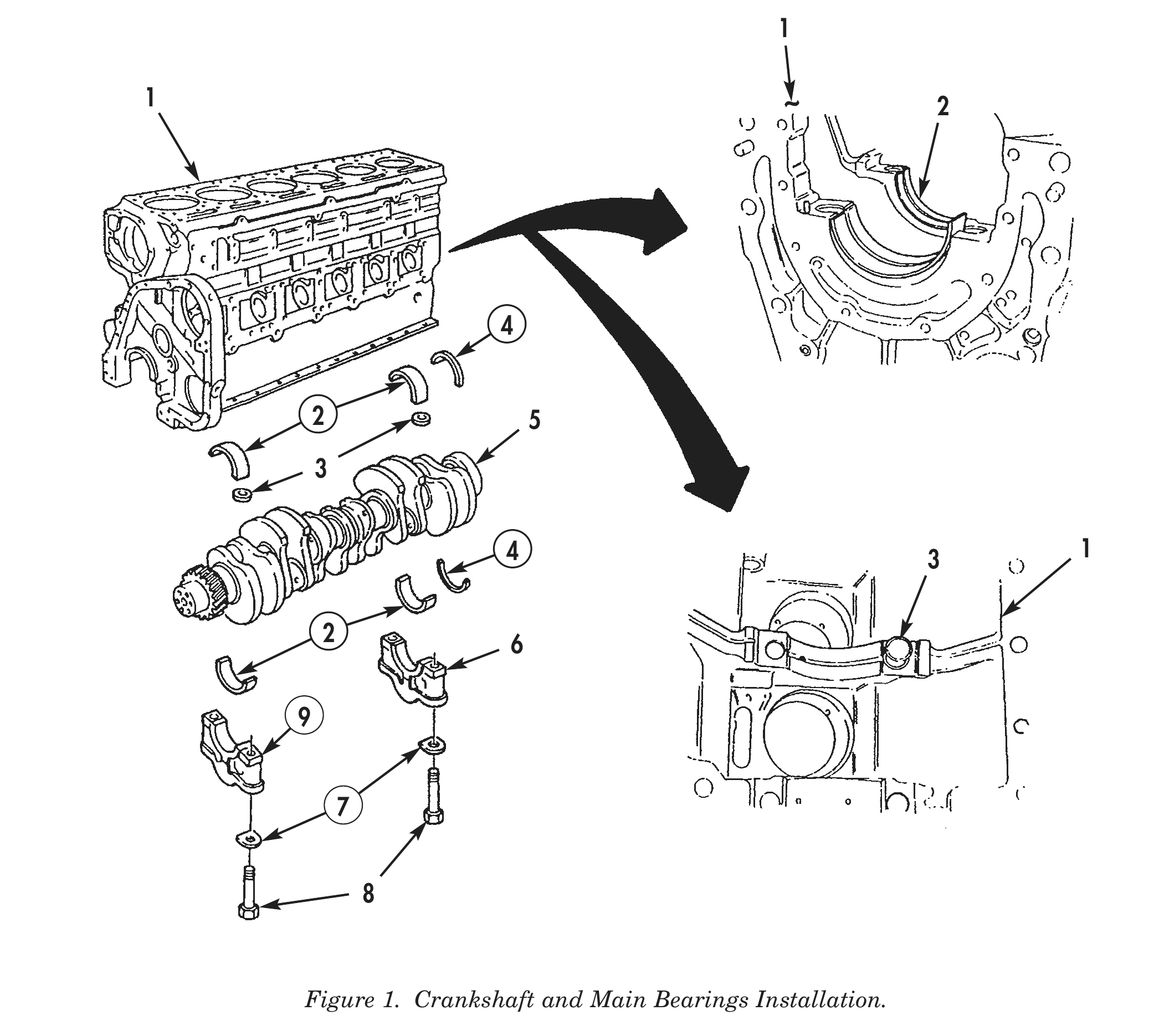
1. Apply lubricating oil to seven new upper main bearing halves (2) and retaining rings (3). Install seven new upper main bearing halves (2) and retaining rings (3) on cylinder block (1).
2. Using lifting device or lifting strap, lower crankshaft (5) on cylinder block (1).
3. Install four new upper thrust bearing washers (4) into position on No. 7 journal of crankshaft (5).
4. Install seven new lower main bearing halves (2) on crankshaft (5). Ensure lower main bearing halves (2) are aligned with retaining rings (3).
5. Position No. 1 through No. 6 bearing caps (9) on cylinder block (1).
6. Install lower thrust bearing washers (4) on No.7 bearing cap (6).
CRANKSHAFT AND MAIN BEARINGS (Contd)
7. Position No. 7 bearing cap (6) and thrust bearing washers (4) on cylinder block (1).
8. Apply OE/HDO 30 lubricating oil to threads of fourteen new screws (8) and new lockplates (7).
9. Install fourteen screws (8) and lockplates (7) on bearing caps (9) and (6) on cylinder block (1) finger-tight.
1 ~
2 5
4 3 1
2 6
CRANKSHAFT AND MAIN BEARINGS (Contd)
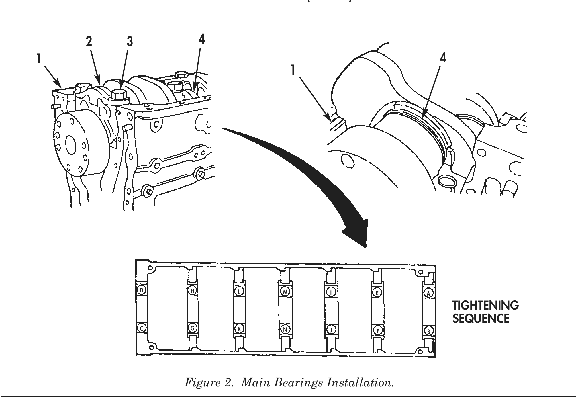
10. Using rubber mallet, strike bearing caps (2) into position on cylinder block (1).
11. Tighten screws (3) 250–260 lb-ft (339–353 N•m) in sequence as shown in figure 2.
12. Loosen fourteen screws (3) three to five threads, or a minimum of three complete turns.
13. Repeat step 11.
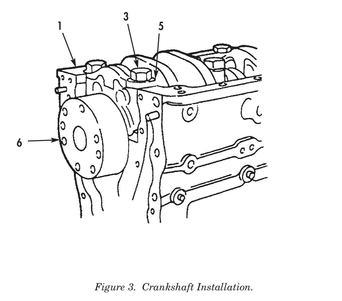
14. Using hands, rotate crankshaft (6). If crankshaft (6) does not rotate freely, refer to WP 0016 00, Crankshaft Cleaning and Inspection.
15. Install dial indicator on rear of cylinder block (1) with contact tip resting on crankshaft (6) flange end face.
16. Using prybar, pry crankshaft (6) toward front of cylinder block (1).
17. Remove prybar and set dial indicator to zero.
18. Pry crankshaft (6) toward rear of cylinder block (1). Total end clearance for new crankshaft (6) and new thrust bearing washers (4) should be 0.007–0.018 in. (0.178–0.457 mm). Maximum clearance for worn parts is 0.022 in. (0.559 mm).
19. If clearance is less than 0.007 in. (0.178 mm), proceed as follows:
a. Loosen fourteen screws (3) one turn.
b. Pry crankshaft (6) toward front and rear of cylinder block (1).
c. Tighten fourteen screws (3) according to steps 11–13.
d. Recheck end clearance.
20. Bend tabs of fourteen lockplates (5) against heads of fourteen screws (3).
CAMSHAFT
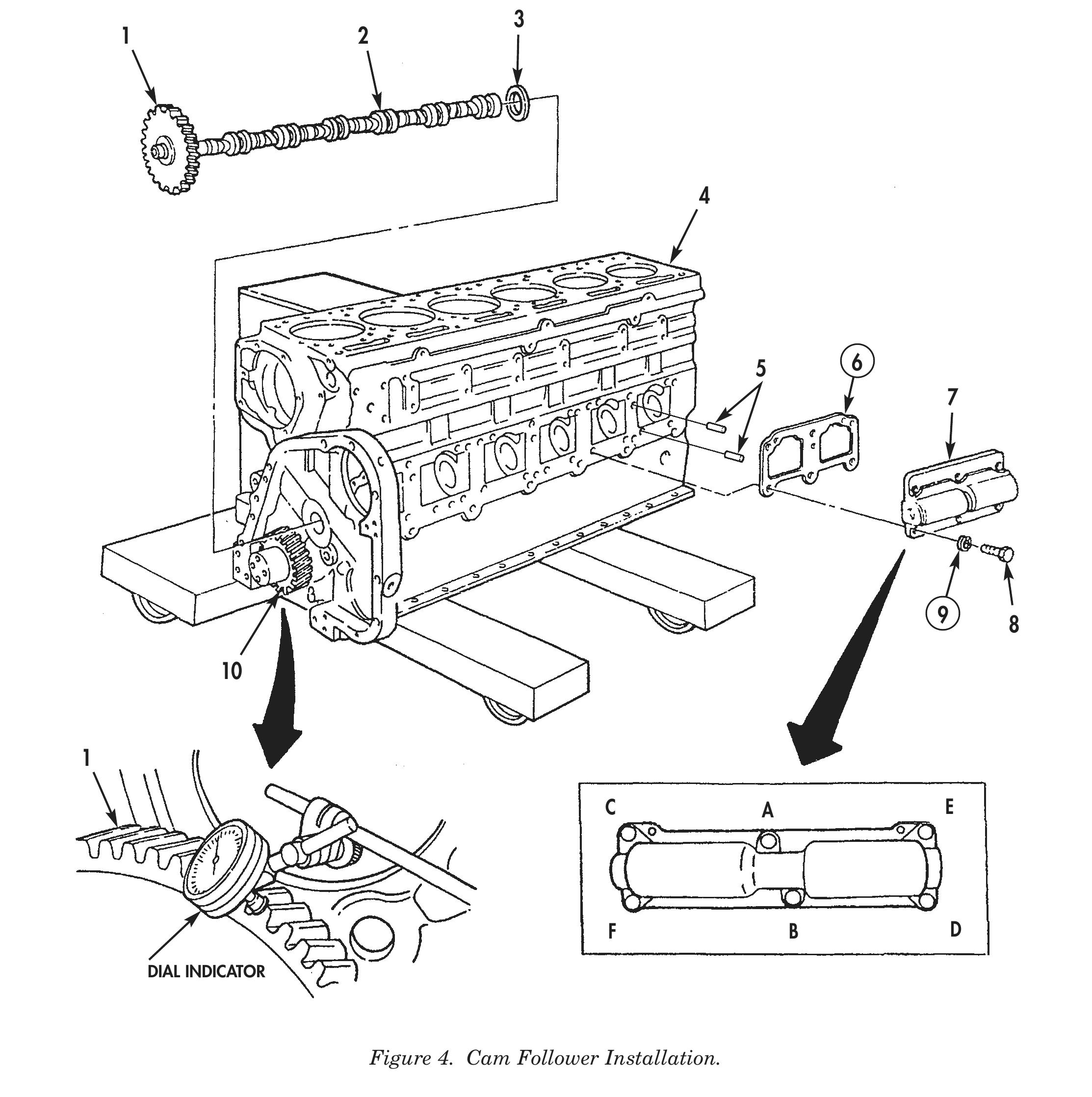
1. Using high-pressure lubricant, coat both sides of thrust washer (3) and slide thrust washer (3) over end of camshaft (2) until seated next to camshaft gear (1).
2. Apply high-pressure lubricant to camshaft (2) lobes.
3. Install camshaft (2) in cylinder block (4).
4. Line up timing mark O on camshaft gear (1) with timing mark O on crankshaft gear (10) and fully seat camshaft (2) and thrust washer (3) against cylinder block (4). Remove camshaft pilot tools from camshaft (2), if utilized.
5. Install dial indicator on front of cylinder block (4), and position tip of dial indicator against tooth on camshaft gear (1).
6. Rotate camshaft gear (1) as far as it will freely move. Ensure crankshaft gear (10) does not move.
7. Turn dial indicator to zero.
8. Rotate camshaft gear (1) in opposite direction as far as it will freely move. Dial indicator reading shows amount of backlash between gears.
9. Normal backlash is 0.004–0.016 in. (0.102–0.406 mm) between new camshaft gear (1) and new crankshaft gear (10). Minimum backlash for new camshaft gear (1) is 0.002 in. (0.051 mm). Gears will begin to make noise if backlash exceeds 0.010 in. (0.254 mm). If noise is acceptable, do not replace gears unless backlash exceeds 0.020 in. (0.508 mm).
10. Install new cam follower housing gasket (6) on two dowel pins (5).
11. Install cam follower housing (7) with six screws (8) and new lockwashers (9) on cylinder block (4). Tighten screws (8) 15 lb-ft (20 N•m) in tightening sequence shown in figure 4, and then tighten 30–35 lb-ft (41–48 N•m) in sequence shown in figure 4.
PISTONS AND CONNECTING RODS
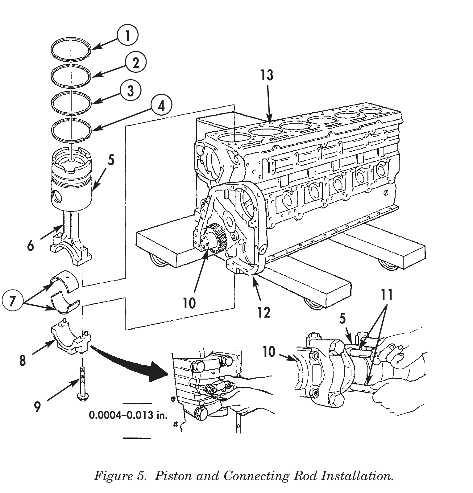
1. Using piston ring expander, install two new compression rings (1) and (3) and two new piston rings (2) and (4) on piston and connecting rod assembly (5). Stagger ring gaps so they are not in line with each other or with piston pin.
2. Install new upper rod bearing half (7) on piston and connecting rod assembly (5). Ensure oil hole in bearing half (7) lines up with oil hole in connecting rod (6).
3. Install new lower rod bearing half (7) on connecting rod cap (8).
4. Using clean lubricating oil, lubricate two rod bearing halves (7).
5. Immerse piston (5) into container of clean lubricating oil.
6. Install two connecting rod guide pins (11) on piston and connecting rod assembly (5).
7. Using piston ring compressor, compress rings (1), (2), (3), and (4) on piston and connecting rod assembly (5).
8. Place cylinder block (12) in vertical position with rear of cylinder block (12) facing down.
9. Rotate crankshaft (10) until journal for piston and connecting rod assembly (5) is installed at bottom dead center.
10. Position piston and connecting rod assembly (5) toward camshaft side of cylinder block (12).
11. Push piston (5) through piston ring compressor and into cylinder liner (13). Ensure piston (5) moves freely in cylinder liner (13). If piston (5) does not move freely, remove and check for broken rings.
12. Using connecting rod guide pins (11), pull connecting rod (6) in position against crankshaft (10).
13. Remove two connecting rod guide pins (11) from piston and connecting rod assembly (5).
14. Install connecting rod cap (8) on crankshaft (10) and on piston and connecting rod assembly (5). Ensure numbered side of connecting rod cap (8) is on same side as numbered side of connecting rod assembly (5).
15. Using lubricating oil, lubricate two bolts (9).
16. Install two bolts (9) on connecting rod cap (8) and connecting rod (6). Tighten bolts (9) as shown in table 1.
17. Check piston and connecting rod assembly (5) side-to-side movement. Piston and connecting rod assembly (5) must move freely on crankshaft journal with hand pressure. If connecting rod does not move freely, remove connecting rod cap (8) and check for dirt, damage, or improper bearing half (7).
18. Using feeler gauge, check side clearance of connecting rod cap (8) and crankshaft (10). Side clearance must be 0.004–0.013 in. (0.102–0.330 mm).
PISTONS AND CONNECTING RODS (Contd)

                       Table 1. Tightening Sequence for Piston and Connecting Rod Bolts.
               STEP SEQUENCE                           MINIMUM                     MAXIMUM
      1. Tighten to                          70 lb-ft (95 N•m)         75 lb-ft (102 N•m)
      2. Tighten to                          140 lb-ft (190 N•m)       150 lb-ft (230 N•m)
      3. Loosen completely                                —                          —
      4. Tighten to                          25 lb-ft (34 N•m)         30 lb-ft (41 N•m)
      5. Tighten to                          70 lb-ft (95 N•m)         75 lb-ft (102 N•m)
      6. Tighten to                          140 lb-ft (190 N•m)       150 lb-ft (230 N•m)

                                     1
                                         2
                                                                 13
                                     3
                                             4

                                 5

                   6

           7                                                                 11
                                                 10
                                                              12      5

                                                                 10
               8

                   9          0.0004–0.013 in.

                               Figure 5. Piston and Connecting Rod Installation.
ACCESSORY DRIVE HOUSING
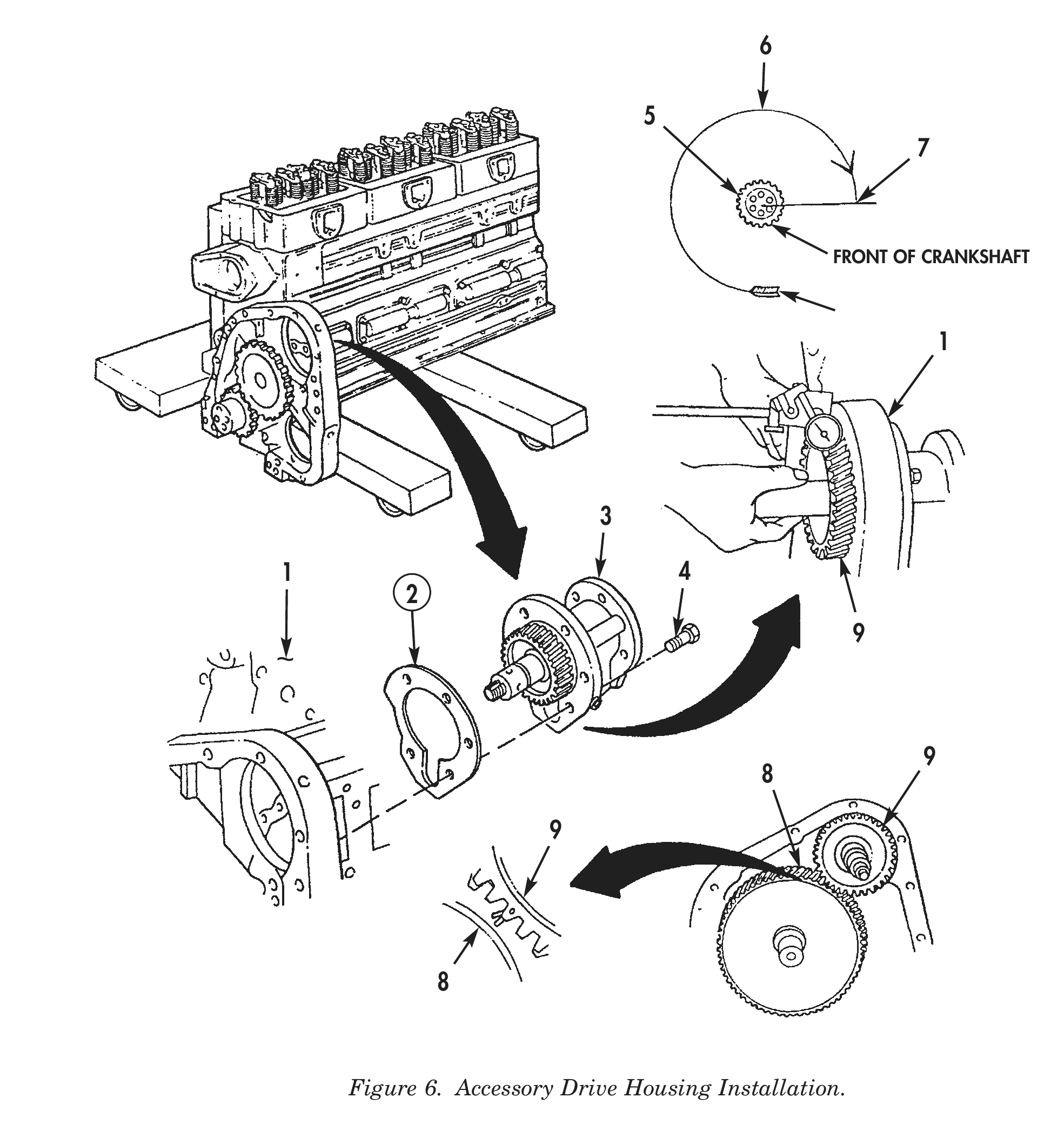
1. Turn crankshaft (5) in direction of engine rotation until No. 1 cylinder is at Top Dead Center (TDC) of compression stroke (6).
2. Turn crankshaft (5) in direction of engine rotation to 90° past TDC (7).
3. Position accessory drive housing (3) and new gasket (2) on cylinder block (1). Ensure that timing mark on accessory drive gear (9) lines up with timing mark on camshaft gear (8). This alignment is necessary so that valve and injector adjustments marks on accessory drive pulley will be correctly aligned.
4. Install five bolts (4) on accessory drive housing (3). Tighten bolts (4) 40–45 lb-ft (54–61 N•m).
5. Install dial indicator on front of cylinder block (1) and position tip of dial indicator against tooth of accessory drive gear (9).
6. Rotate accessory drive gear (9) as far as it will freely move. Ensure camshaft gear (8) does not move.
7. Turn dial on indicator to zero and rotate accessory drive gear (9) in opposite direction. Reading on dial indicator shows amount of backlash between gears.
8. Normal backlash between new accessory drive gear (9) and new camshaft gear (8) is 0.004–0.016 in. (0.102–0.406 mm). Backlash for new accessory drive gear (9) must be at least 0.002 in. (0.051 mm). If backlash is more than 0.016 in. (0.406 mm), remove accessory drive housing (3) and replace accessory drive gear (9).
OIL PUMP
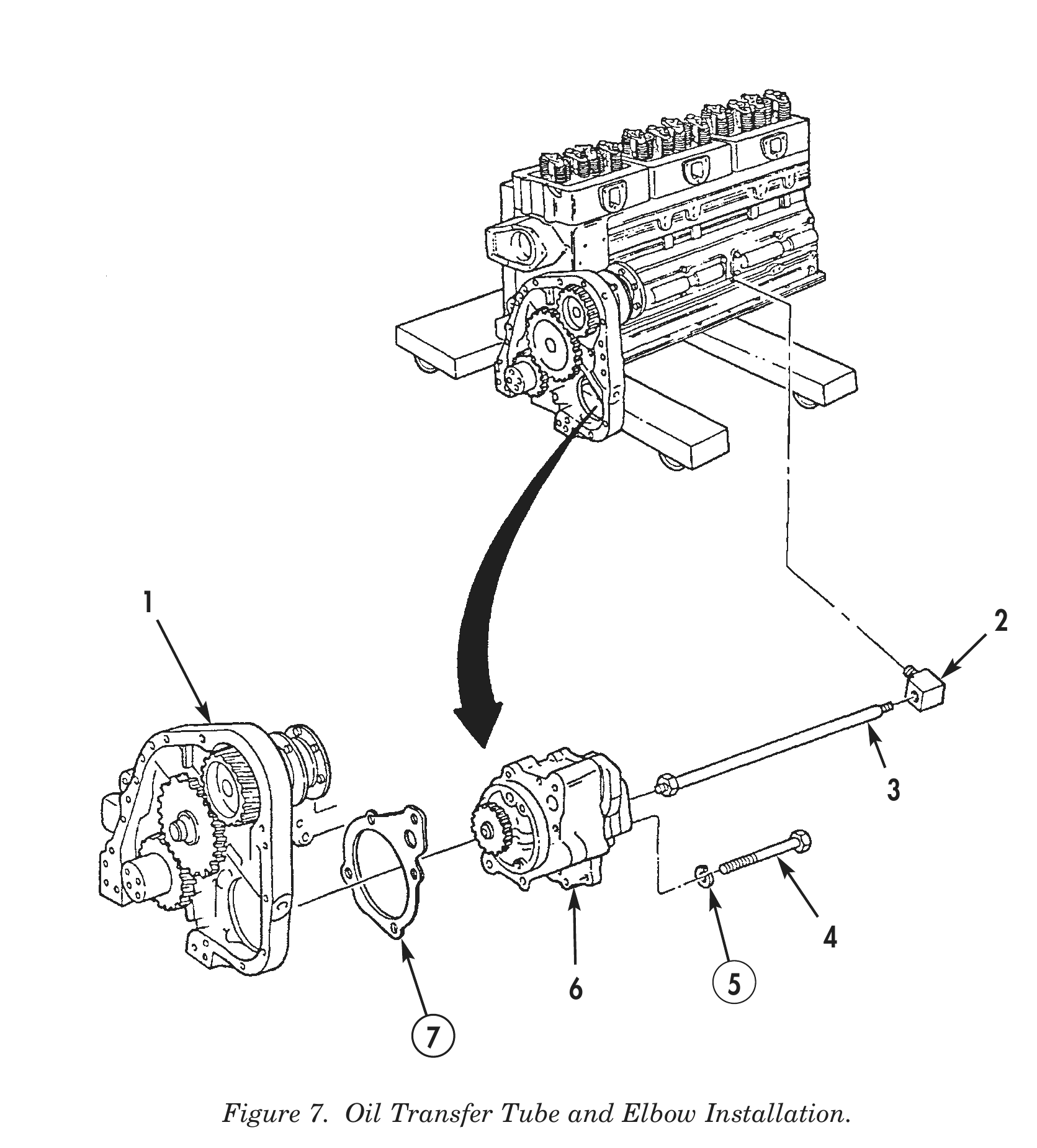
1. Apply pipe sealant to threads of elbow (2).
2. Install elbow (2) on cylinder block (1).
3. Apply pipe sealant to threads of oil transfer tube (3).
4. Install oil transfer tube (3) on elbow (2).
5. Install loose end of oil transfer tube (3) on oil pump (6).
6. Install oil pump (6) and new gasket (7) on cylinder block (1) with five bolts (4) and new lockwashers (5). Tighten bolts (4) 45 lb-ft (61 N•m).
6 5
OIL PUMP (Contd)
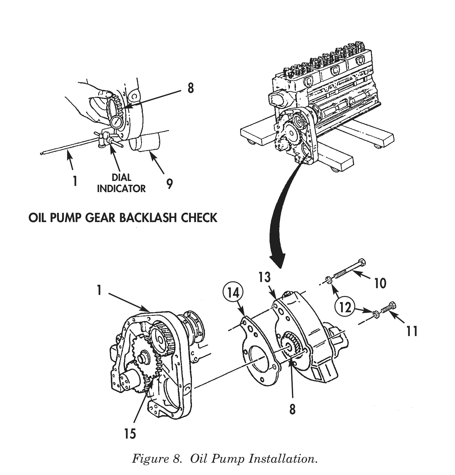
7. Install oil pump (13) and new gasket (14) on cylinder block (1) with five new lockwashers (12), two short bolts (11), and three long bolts (10). Tighten bolts (10) and (11) 40 lb-ft (54 N•m).
8. Install dial indicator and dial gauge attachment on front of cylinder block (1), and position tip of dial indicator against tooth of pump drive gear (8).
9. Rotate pump drive gear (8) as far as it will freely move. Ensure that camshaft gear (15) does not move.
10. Turn dial indicator to zero.
11. Rotate pump drive gear (8) in opposite direction. The reading of dial indicator shows the amount of backlash between gears. Minimum backlash is 0.002 in. (0.051 mm) and maximum backlash is 0.016 in. (0.406 mm). Replace pump drive gear if not within specifications.
DIAL
1 INDICATOR 9
OIL PUMP GEAR BACKLASH CHECK
13 10 1 14
ACCESSORY DRIVE PULLEY
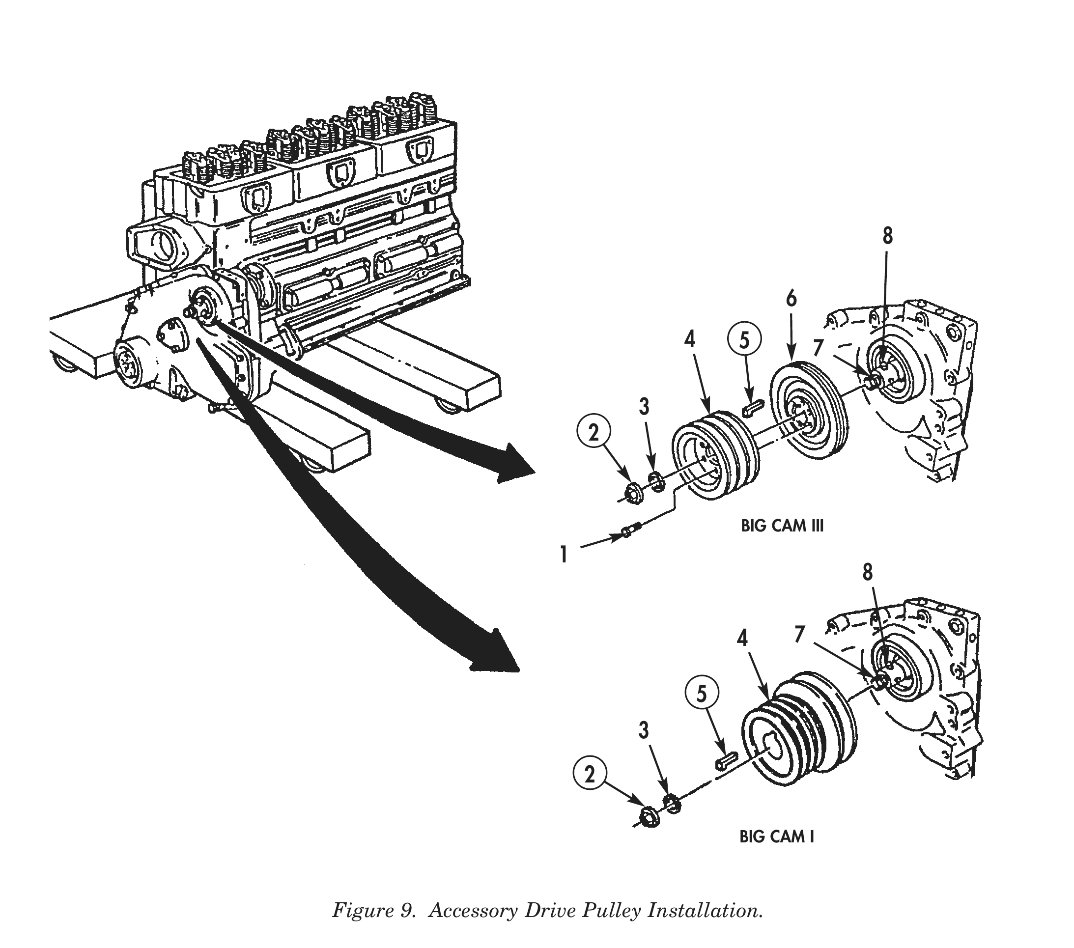
1. Apply high pressure lubricant to accessory driveshaft (7).
2. Install new keyway seal (5) on accessory driveshaft (7).
3. Align accessory drive pulley (4) keyway with dowel pin (8) on accessory driveshaft (7).
4. Using pulley installation tool, install accessory drive pulley (4) on accessory driveshaft (7).
5. Align keyway seal (5) on keyway of accessory drive pulley (4). Ensure short leg of keyway seal (5) faces toward inside of accessory driveshaft (7) and washer (3) or it will crush against L of seal (5).
6. Align accessory drive pulley (6) keyway with dowel pin (8) on accessory driveshaft (7).
7. Align new keyway seal (5) on keyway of accessory drive pulley (6). Ensure short leg of keyway seal (5) faces toward inside of accessory driveshaft (7) and washer (3) or it will crush against L of seal (5).
8. Install new locknut (2) and washer (3) on accessory driveshaft (7). Tighten locknut (2) 300–310 lb-ft (407–420 N•m).
9. Position accessory drive pulley assembly (4) on accessory drive pulley (6) with six bolts (1). Tighten bolts 40–45 lb-ft (54–61 N•m).
AIR COMPRESSOR
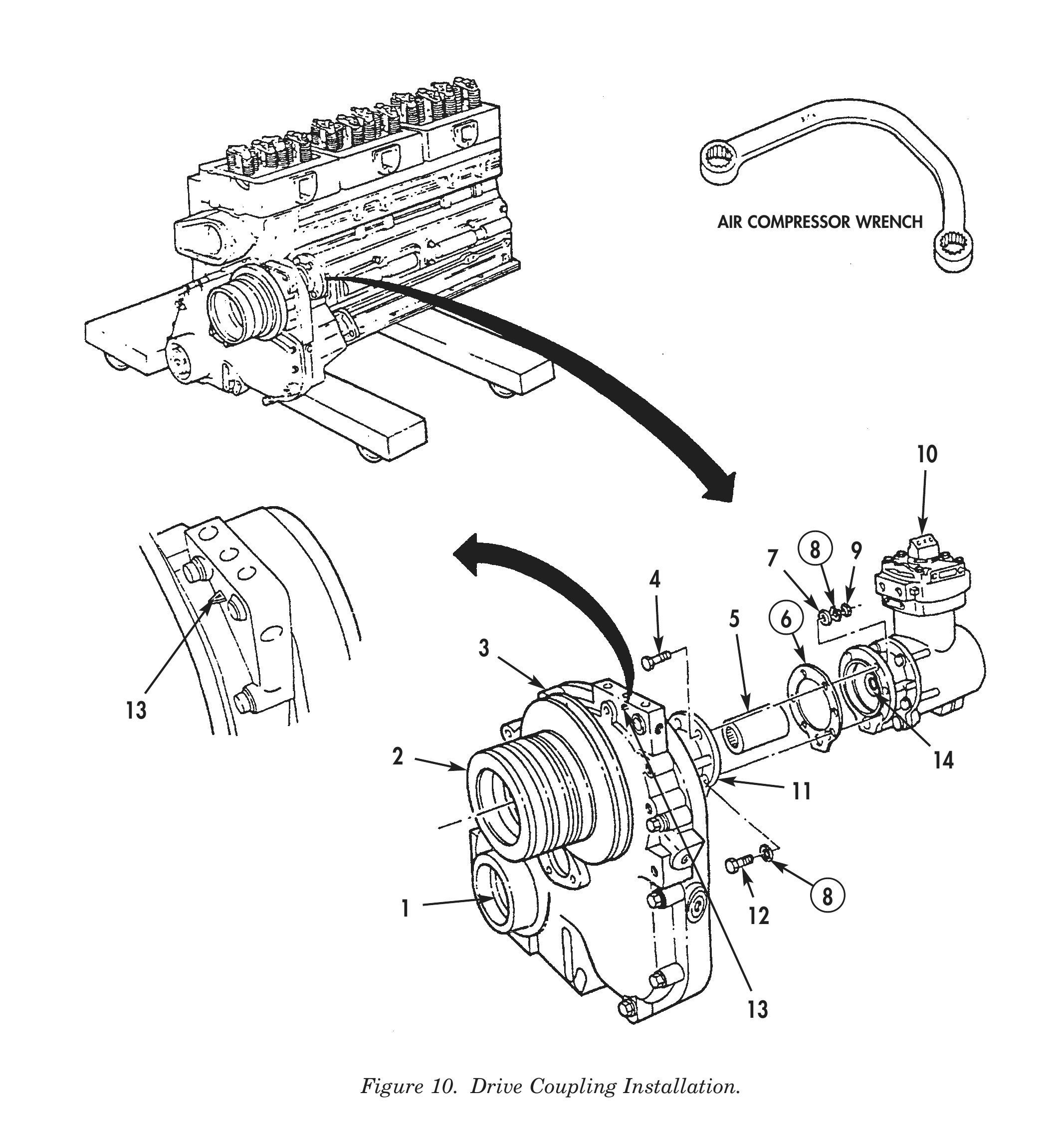
1. Rotate crankshaft (1) until valve set mark A on accessory drive pulley (2) is aligned with pointer (13) on front gear cover (3).
2. Rotate air compressor crankshaft (14) until scribe mark on hub is positioned halfway between 9 and 10 o’clock.
3. Install drive coupling (5) on air compressor (10).
4. Install air compressor (10) and new gasket (6) on accessory drive housing (11) with two screws (4) and (12), washers (7), four new lockwashers (8), and two nuts (9). Using air compressor wrench, tighten screws (4) and (12) 40–45 lb-ft (54–62 N•m).
AIR COMPRESSOR (Contd)
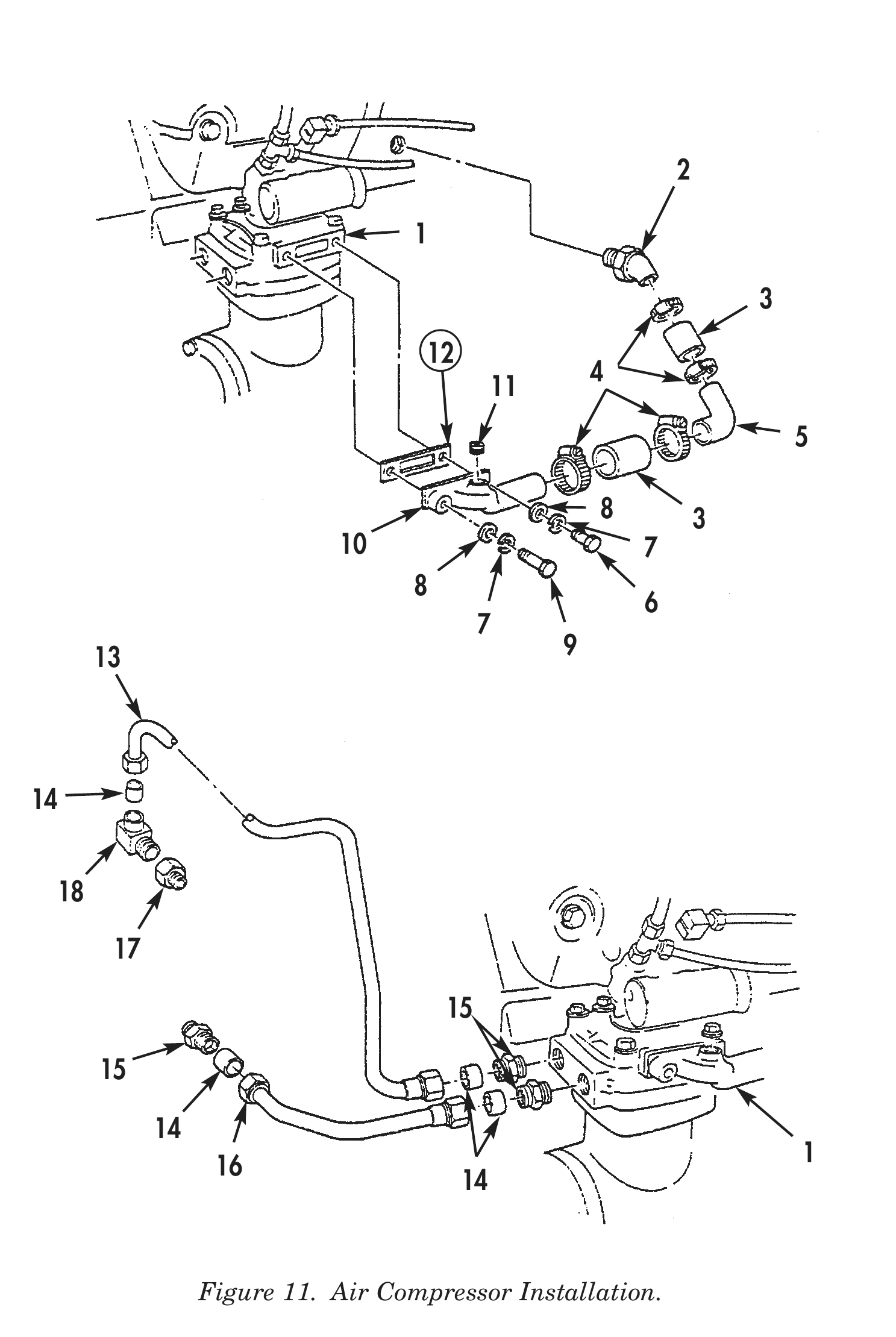
5. Apply pipe sealant to threads of plug (11), and install air inlet connector (10) and new gasket (12) on air compressor (1) with two washers (8), new lockwashers (7), screws (9) and (6), and plug (11).
6. Install two air inlet hoses (3) and tube (5) on air inlet connector (10) and elbow (2) with four clamps (4).
7. Apply pipe sealant to threads of three adapters (15) and, install adapters (15), coupling (17), and elbow (18) on air compressor (1).
8. Install four bushings (14), coolant outlet tube (13), and coolant inlet tube (16) on three adapters (15) and elbow (18).
FRONT GEAR COVER
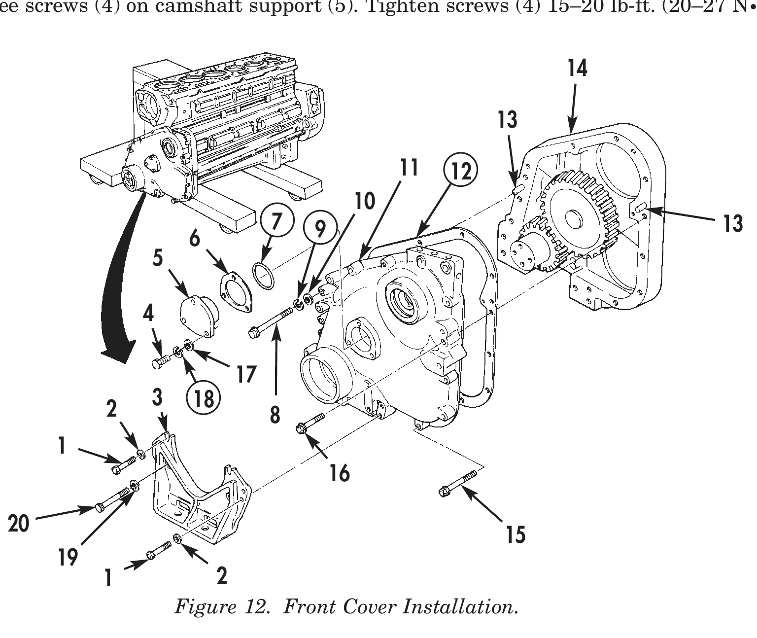
1. Remove three screws (4), lockwashers (18), and washers (17) from camshaft support (5).
2. Remove three screws (4) from camshaft support (5).
3. Remove camshaft support (5), shim pack (6), and seal (7) from gear cover (11).
4. Coat new gasket (12) with high pressure lubricant and install on gear cover (11).
5. Install gear cover (11) and gasket (12) on two dowels (13) and cylinder block (14).
6. Install screw (8), new lockwasher (9), washer (10), screw (15), and nine screws (16) on gear cover (11) and cylinder block (14). Tighten screws (16), (8), and (15) 45–55 lb-ft (61–75 N•m).
7. Install three screws (8), screw (15), and nine screws (16) on gear cover (11) and cylinder block (14). Tighten screws (8), (15), and (16) 45–55 lb-ft (61–75 N•m).
8. Position front engine support (3) on gear cover (11).
9. Install six screws (1), washers (2), two screws (20), and washers (19) on front engine support (3) and gear cover (11). Tighten screws (1) and (20) 45–55 lb-ft (61–75 N•m).
10. Install six screws (1), washers (2), and two screws (20) on front engine support (3) and gear cover (11). Tighten screws (1) and (20) 45–55 lb-ft (61–75 N•m).
11. Using straightedge and feeler gauge, check alignment of oil pan mounting flange on gear cover (11) with oil pan mounting flange on cylinder block (14). Gear cover flange must be even with front cylinder block flange within 0.004 in. (0.102 mm).
FRONT GEAR COVER (Contd)
12. Install dial indicator on front of crankshaft and position tip of dial indicator against inner surface of crankshaft seal bore.
13. Turn dial of indicator to zero.
14. Rotate crankshaft one complete revolution. Reading on dial indicator shows difference. If total dial indicator reading exceeds 0.010 in. (0.254 mm), remove, clean, and relocate between common centers.
15. Remove shim pack (6) and seal (7) from camshaft support (5).
16. Install camshaft support (5) on gear cover (11) and hold against end of camshaft. Ensure camshaft is pushed against cylinder block (14).
17. Using feeler gauge, measure space between mounting flange of camshaft support (5) and gear cover (11). Use measurement to determine thickness of shim pack (6) needed to provide 0.008–0.130 in. (0.203–3.302 mm) clearance. Shim packs (6) are available in four different thicknesses.
18. Remove camshaft support (5) from gear cover (11).
19. Install shim pack (6) and new seal (7) on camshaft support (5).
20. Install camshaft support (5), shim pack (6), and seal (7) on gear cover (11).
21. Install three screws (4), new lockwashers (18), and washers (17) on camshaft support (5). Tighten screws (4) 15–20 lb-ft. (20–27 N•m).
22. Install three screws (4) on camshaft support (5). Tighten screws (4) 15–20 lb-ft. (20–27 N•m).
11 12 7 9 13
3 18 2 8
1 2 Figure 12. Front Cover Installation.
FLYWHEEL, FLEXPLATE, AND FLYWHEEL HOUSING
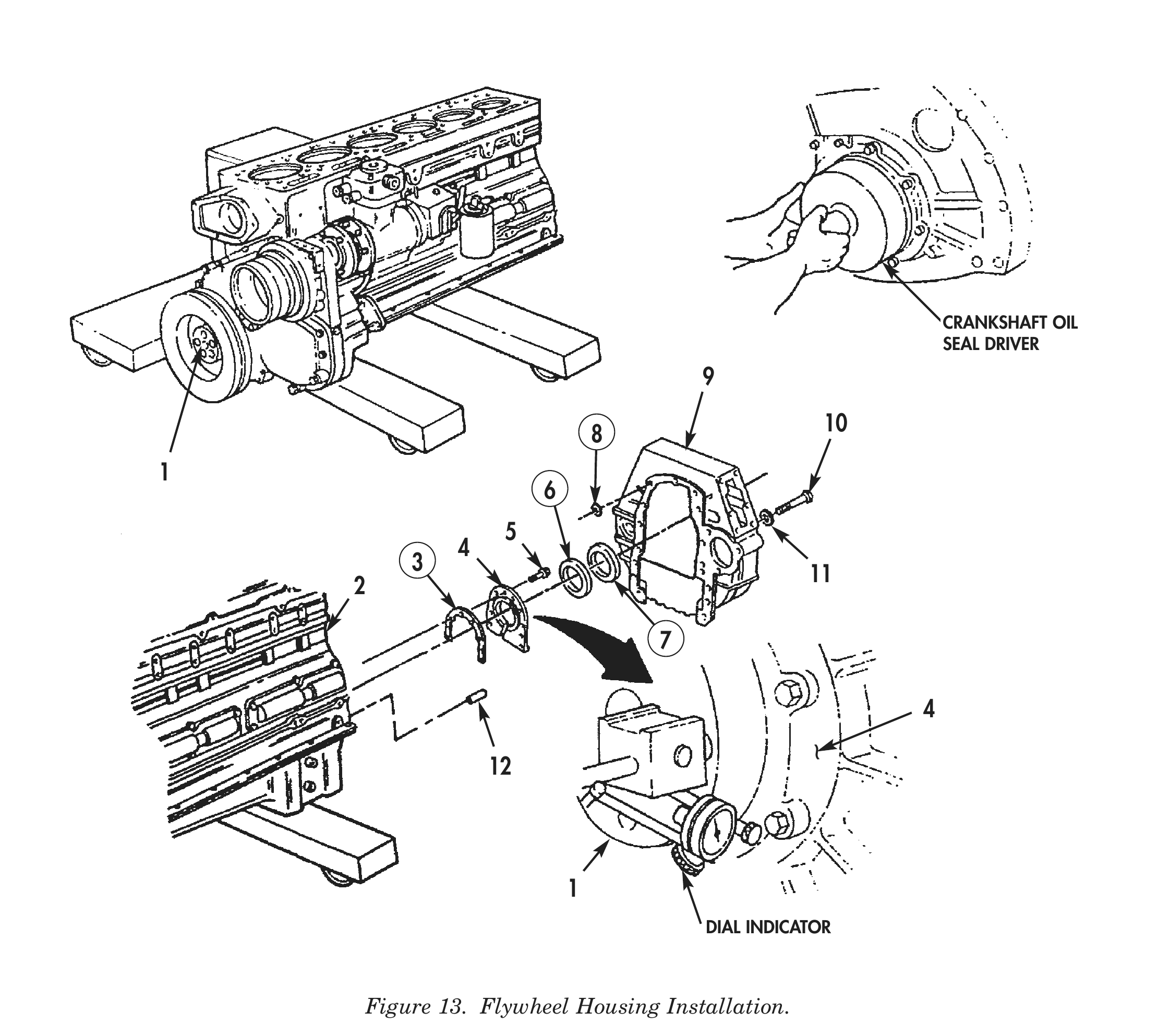
1. Install new gasket (3) and rear cover (4) on cylinder block (2) with eight screws (5). Tighten screws (5) only enough to hold rear cover (4) in position.
2. Using crankshaft oil seal driver, align rear cover (4) with crankshaft (1).
3. Using dial indicator, check alignment of rear cover (4) to crankshaft (1). Rear cover (4) must be on common center with crankshaft (1) within 0.010 in. (0.254 mm). Rear cover (4) must be square to centerline of crankshaft (1) within 0.010 in. (0.254 mm). Rear cover (4) must be within 0.004 in. (0.102 mm) of being flat with oil pan flange of cylinder block (2).
4. Tighten eight screws (5) 30–35 lb-ft (41–48 N•m). Cut off excess gasket (3) material so that gasket (3) is even with, or not more than, 0.010 in. (0.254 mm) above oil pan flange.
5. Install new rear main seal (6) on crankshaft (1). Position largest diameter of assembly tool toward cylinder block (2).
6. Push rear main seal (6) from assembly tool onto crankshaft (1). Using crankshaft rear oil seal driver, drive rear main seal (6) on rear cover (4).
7. Remove two dowel pins (12) if installing new flywheel housing (9), or if dowel is damaged or outside diameter is less than 0.5005 in. (12.713 mm), and install two flywheel housing guide pins in their place.
8. Install new seal (7) on crankshaft (1).
9. Install eleven new O-rings (8) on flywheel housing (9).
10. Install flywheel housing (9) on cylinder block (2) with seven of nine screws (10) and washers (11). Tighten screws (10) 10–20 lb-ft (14–27 N•m).
11. Remove two flywheel housing (9) guide pins, if installed, and install two remaining screws (10) and washers (11) on flywheel housing (9).
FLYWHEEL, FLEXPLATE, AND FLYWHEEL HOUSING (Contd)
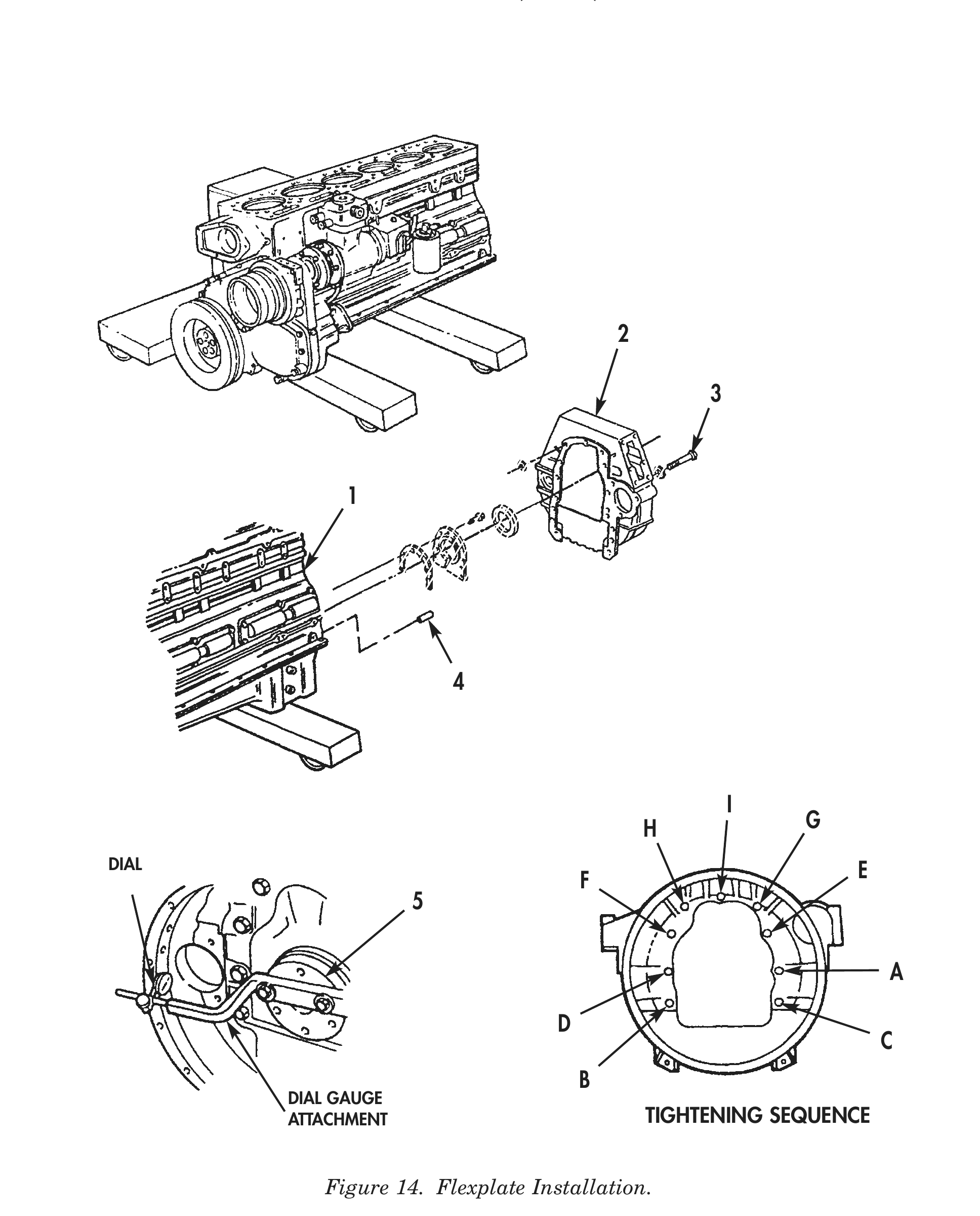
12. Install dial gauge attachment and dial indicator on crankshaft (5).
13. Using chalk, mark flywheel housing (2) at 12, 3, 6, and 9 o’clock positions.
14. Check readings at 3 o’clock and 9 o’clock positions.
15. Check readings at 12 o’clock and 6 o’clock positions.
16. After readings are within limits, tighten screws (3) 140–160 lb-ft (190–217 N•m) in sequence shown in figure 14.
17. Adjust dial indicator to measure alignment of face on flywheel housing (2).
18. Push crankshaft toward front of cylinder block (1) to remove crankshaft end clearance.
19. Rotate crankshaft (5) and check alignment of face on flywheel housing (2).
20. If dowel pins (4) were removed from cylinder block (1), use drill and fixture to ream dowel holes to next oversize and install two new dowel pins (4), if required.
I
H            G
DIAL                                                                    E
F
A
D C B
DIAL GAUGE
ATTACHMENT                                TIGHTENING SEQUENCE
FLYWHEEL, FLEXPLATE, AND FLYWHEEL HOUSING (Contd)
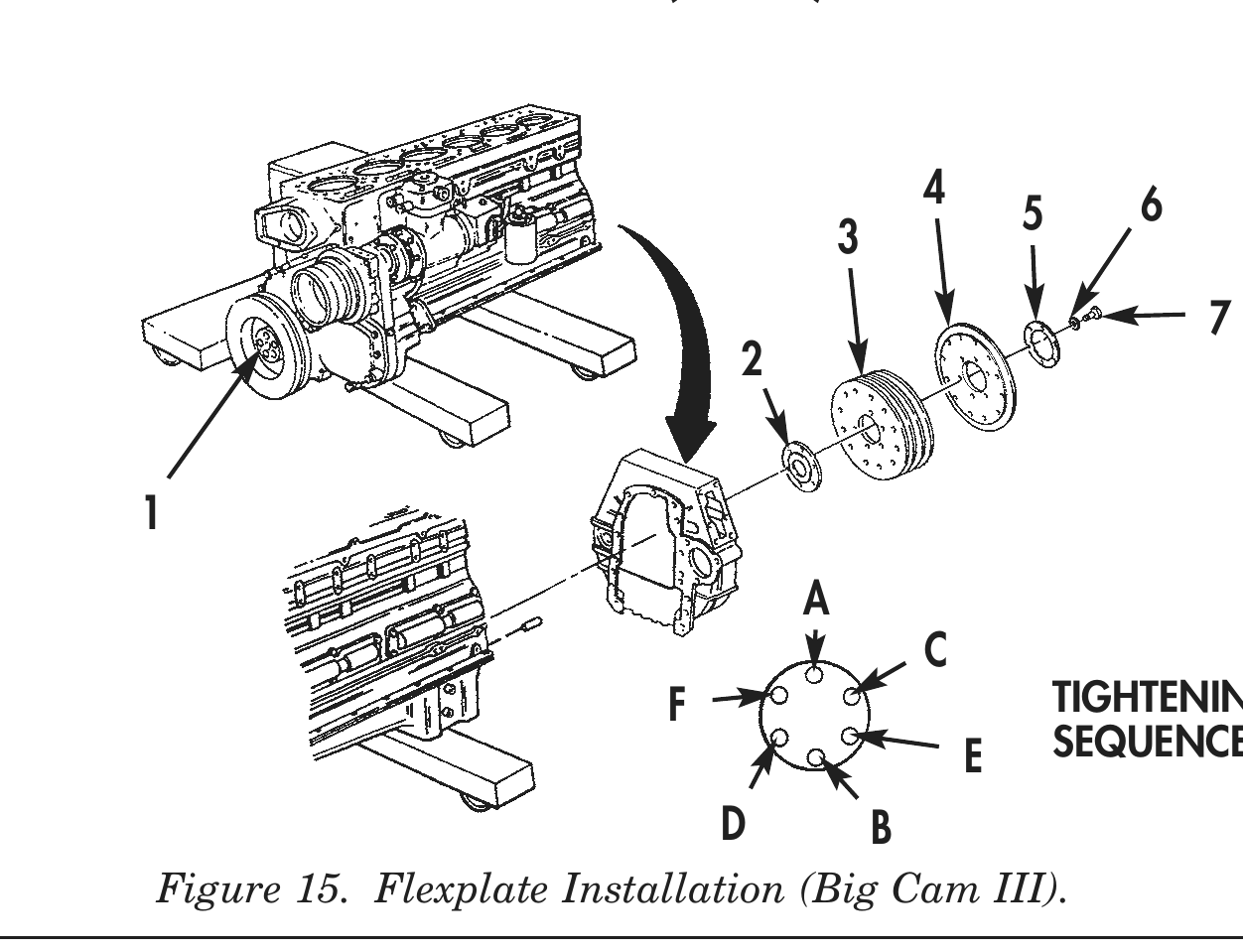
21. Apply a thin coat of lubricating oil to threads of screws (7) and face of washers (6)
22. Install retaining plate (2), flexplates (3), flywheel (4), and washer bearing (5) on crankshaft (1) with six screws (7) and washers (6). Tighten screws (7) 200–220 lb-ft (271–298 N•m) in sequence shown in figure 15.
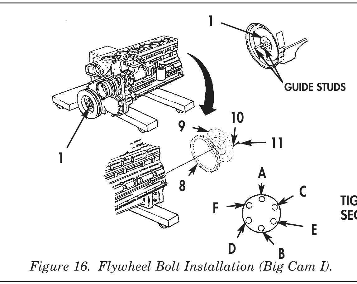
23. Install two 5/8-18 x 6 in. guide studs in opposite holes on crankshaft (1) until fully seated.
24. Apply lubricating oil to threads of screws (11) and face of washers (10). Allow excess oil to drain from screw threads.
25. Install flywheel (9) and spacer gear (8) on crankshaft (1) with four screws (11) and washers (10). Tighten screws (11) hand-tight in sequence shown in figure 16.
26. Remove two 5/8-18 x 6 in. guide studs from crankshaft (1).
27. Install two remaining screws (11) and washers (10) on flywheel (9). Tighten screws (11) 70 lb-ft (95 N•m) then 140 lb-ft (190 N•m) and finally 200–220 lb-ft (271–298 N•m) in sequence shown in figure 16.
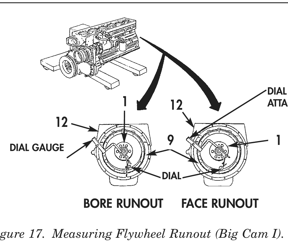
28. Install dial gauge attachment and dial indicator on flywheel housing (12).
29. Position contact tip of dial indicator against wide diameter of flywheel (9) bore and set dial indicator to zero. Rotate crankshaft (1) one complete revolution. Total indicator reading must not exceed 0.005 in. (0.127 mm).
30. Inspect flywheel (9) face runout and install or reposition dial indicator on flywheel housing (12).
31. Position contact tip of dial indicator against face of flywheel (9) as close to outside diameter as possible. Rotate crankshaft (1) one complete revolution. Total indicator reading must not exceed 0.005 in. (0.127 mm).
4 6
A C
F                                       TIGHTENING
E       SEQUENCE
D               B
GUIDE STUDS
A
8                                   C
TIGHTENING
F                                        SEQUENCE
E
D B
DIAL GAUGE
1 12 ATTACHMENT
DIAL GAUGE
9 1
DIAL
BORE RUNOUT               FACE RUNOUT
OIL PAN
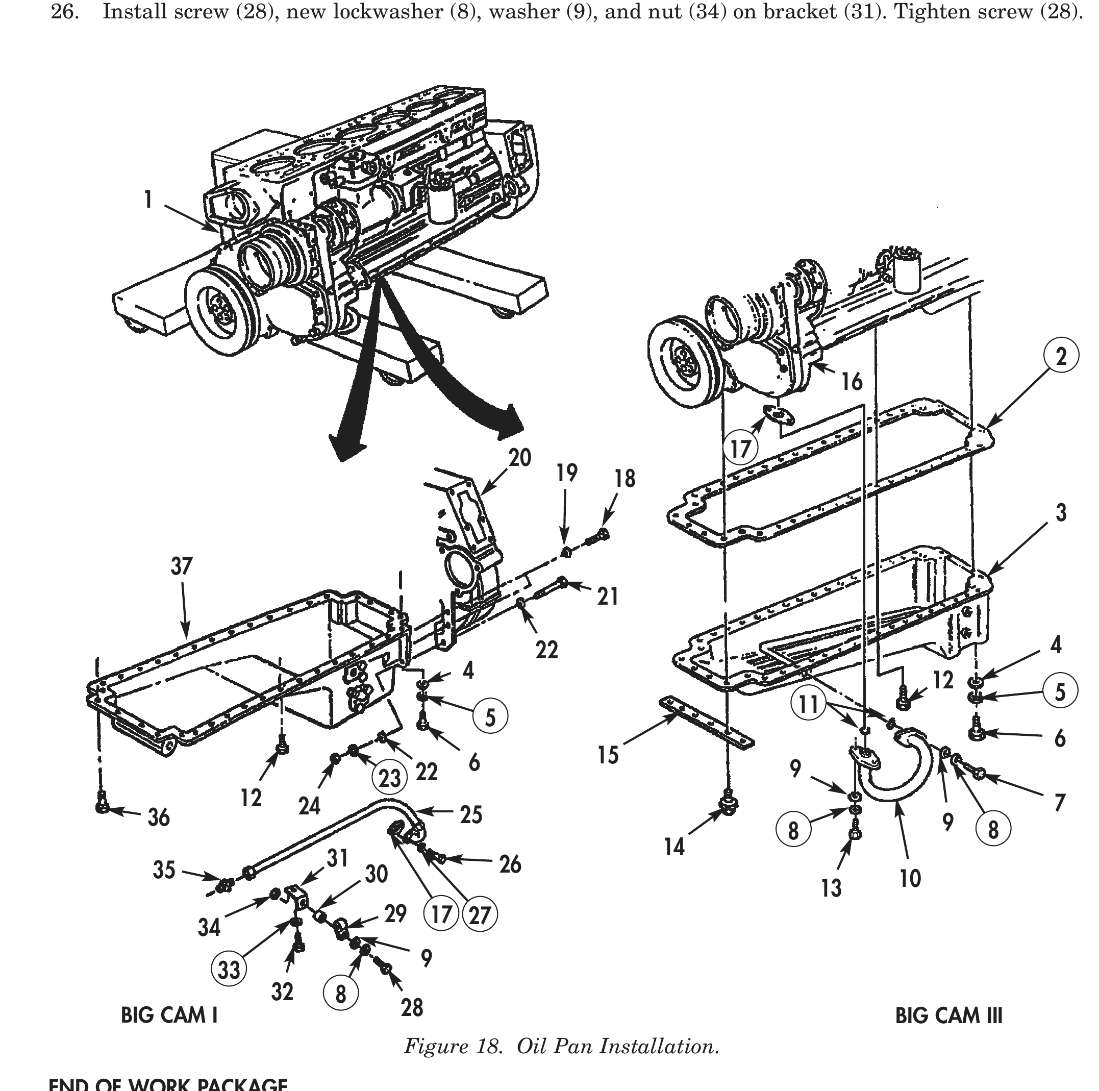
1. Apply a thin coat of GAA grease to oil pan (3) or (37) mounting surface.
2. Install new gasket (2) on cylinder block (1).
3. Position oil pan (3) or (37) on cylinder block (1).
4. Install twenty eight screws (12) on oil pan (3) or (37). Do not tighten screws (12) at this time.
5. Install four screws (6), new lockwashers (5), and washers (4) on oil pan (3) or (37). Do not tighten screws (6) at this time.
6. Install engine shipping support (15) on oil pan (3) or (37) with four screws (14) or (36). Do not tighten screws (14) or (36) at this time.
7. Install two screws (18) and washers (19) on middle holes of oil pan (37).
8. Finger-tighten two screws (12) on oil pan (3) or (37).
9. Remove two screws (18) and washers (19) from oil pan (37).
10. Finger-tighten four screws (12) on oil pan (3) or (37).
11. Tighten twenty-eight screws (12) and four screws (14) or (36) 35–40 lb-ft (41–48 N•m).
12. Install four screws (18) and washers (19) on oil pan (37). Do not tighten screws (18) at this time.
13. Install two screws (21), four washers (22), new lockwashers (23), and nuts (24) on oil pan (37). Do not tighten screws (21) at this time.
14. Tighten four screws (18) and two nuts (24) 70–80 lb-ft (95–109 N•m).
15. Tighten screws (6) 15–20 lb-ft (20–27 N•m).
16. Install new gasket (17), and two new O-rings (11) on oil suction tube (10). Position oil suction tube (10) on oil pan (3) and oil pump (16).
17. Install oil suction tube (10) on oil pan (3) and oil pump (16) with two screws (7), screws (13), four new lockwashers (8), and washers (9). Tighten screws (7) 30–35 lb-ft (41–48 N•m). Tighten screws (13) 30–35 lb-ft (41–48 N•m).
18. Install oil suction hose (25) and new gasket (17) on oil pan (37) with screws (26) and new lockwashers (27). Do not tighten screws (26) at this time.
19. Install adapter (35) and oil suction hose (25) on oil pump (16) and hand-tighten oil suction hose (25) nut until snug, then tighten oil suction hose (25) nut and additional 1 to 1 ¼ turn.
20. Tighten two screws (26) 30–35 lb-ft (41–48 N•m).
OIL PAN (Contd)
21. Tighten nut on oil suction hose (25) mounting flange until nut is against stop on mounting flange.
22. Remove one screw (12) from left side of oil pan (37).
23. Install bracket (31) on oil pan (37) with screw (32) and new lockwasher (33). Tighten screw (32) 35–40 lb-ft (41–48 N•m).
24. Position clamp (29) on oil suction hose (25).
25. Position spacer (30) between bracket (31) and clamp (29).
26. Install screw (28), new lockwasher (8), washer (9), and nut (34) on bracket (31). Tighten screw (28).
20 17 19 18
22 4 4 12 6 15 23 22 9
               12        24                                                                               7
36                                           25                                                 9
                                                                                 8                   8
                              31                                       14
 35                                30                 26
13 10 29 17 27 32 8 BIG CAM I 28 BIG CAM III Figure 18. Oil Pan Installation.
END OF WORK PACKAGE