Section II. TROUBLESHOOTING
TM 9-2320-363-34-1 · Chapter 2 — Direct and General Support Maintenance Instructions
This section contains troubleshooting, testing, and repair information for the M915 family of vehicles. Make sure the problems are real. Be sure the electrical or hydraulic power is on when needed. Refer to the preliminary troubleshooting procedures before you start troubleshooting, and during troubleshooting when referenced.
Page
Preliminary Troubleshooting Procedures . . . . . . . . . . . . . . . . . . . . . . . . . . . . . . . . . . 2-2
Relieving Hydraulic System Pressure (M916A1 and M916A2) . . . . . . . . . . . . . . . . . . 2-2
Transmission Stall Test . . . . . . . . . . . . . . . . . . . . . . . . . . . . . . . . . . . . . . . . . . . . . . . 2-3
Troubleshooting Symptom Index . . . . . . . . . . . . . . . . . . . . . . . . . . . . . . . . . . . . . . . . 2-4
Troubleshooting Table . . . . . . . . . . . . . . . . . . . . . . . . . . . . . . . . . . . . . . . . . . . . . . . . 2-6
Troubleshooting and Testing the Air Conditioning System (All Except M915A2 and M916A1) . . . . . . . . . . . . . . . . . . . . . . . . . . . . . . . . . . . . 2-28.1
Class I: Seepage of fluid, as indicated by wetness or discoloration, not great enough to form drops.
Class II: Leakage of fluid great enough to form drops, but not enough to cause drops to drip from the item being checked or observed.
Class III: Leakage of fluid great enough to form drops that fall from the item being checked or observed.
Before starting any specific troubleshooting procedures, perform the following procedures:
1. Visually check for ruptured oil hoses or tubes, and for Class II or Class III leaks.
2. Check for mechanical jamming or binding caused by rocks or other foreign matter.
3. Check fluid levels in subject area and service as required (Unit PMCS, TM 9-2320-363-20-1).
Cycle hydraulic winch controls a few times to drain and relieve system pressure.
                                                       NOTE
          To make thorough test of vehicle-mounted transmission, be sure that engine is
          properly tuned and that oil level in transmission is correct.

    Perform transmission stall test when power package (engine and transmission) is not
performing satisfactorily. Purpose 0f test is to determine if transmission or engine is defective.

                                                   WARNING
           Apply parking brake when performing transmission stall test. Block wheels to
           prevent forward or reverse movement. In event of brake failure and/or
           Improper blocking of wheels, vehicle can suddenly move forward or backward
           and could cause personal injury or death.

1.    Block wheels to prevent forward or reverse movement.

2.    Start engine and set parking brake.

3.    Put transfer case in high range and set transmission to 2nd gear.

                                                    CAUTION
            Do not maintain stall condition longer than 30 seconds. Transmission oil can
            become overheated and damage to transmission could occur. Do not allow
            temperature to exceed 300°F (140°C). Keep close check to prevent cooling
            system from overheating.

4.    Accelerate engine to full throttle. Write down maximum rpm that engine will run (torque converter
      stall speed). Stall speed should be 2100 rpm ±150 rpm.

           l      If engine speed is high, go to Transmission Malfunction 10.
           l      If engine speed is low, go to Transmission Malfunction 11.

                                         Troubleshooting Symptom Index

                                                                                               Troubleshooting
Malfunction                                                                                          Procedure
Number                                             Malfunction                                            Page

ENGINE

     1.        ENGINE FAILS TO CRANK . . . . . . . . . . . . . . . . . . . . . . . . . . . . . . . . .    2-5
     2.        ENGINE CRANKS BUT FAILS TO START . . . . . . . . . . . . . . . . . . . . . . . .           2-5
     3.        ENGINE RUNS ERRATICALLY . . . . . . . . . . . . . . . . . . . . . . . . . . . . . . .      2-6
     4.        ENGINE OVERHEATS . . . . . . . . . . . . . . . . . . . . . . . . . . . . . . . . . . . .   2-6
     5.        ENGINE RETARDER (JAKE BRAKE) NOT OPERATING . . . . . . . . . . . . . . . .                 2-6
                                 Troubleshooting Symptom Index (Cont)

                                                                                         Troubleshooting
Malfunction                                                                                    Procedure
Number                                          Malfunction                                         Page

TRANSMISSION

   1.  TRANSMISSION OIL TEMPERATURE GAGE STAYS OVER 251°F (121°C) . . . .                          2-7,
   2.  TRANSMISSION NOISY                                                                          2-9
   3.  TRANSMISSION WILL NOT SHIFT INTO GEAR, SLIPS OUT OF GEAR, OR
          OPERATES ERRATICALLY                                                                     2-11
   4.  OIL LEAKING AT CONVERTER HOUSING : : : : : : : : : : : : : : : : : : : : : : : :            2-13
   5.   EXCESSIVE CREEP IN FIRST AND REVERSE . . . . . . . . . . . . . . . . . . . . .             2-13
   6.  AUTOMATIC SHIFTS OCCUR AT TOO HIGH A SPEED . . . . . . . . . . . . . . . .                  2-14
   7.  AUTOMATIC SHIFTS OCCUR AT TOO LOW A SPEED, OR SHIFTS ROUGH . . .                            2-15
   8.   VEHICLE MOVES IN NEUTRAL. . . . . . . . . . . . . . . . . . . . . . . . . . . . . . .      2-17
   9.   TRANSMISSION SLIPS IN ALL FORWARD GEARS . . . . . . . . . . . . . . . . . .                2-17
   10. HIGH STALL SPEED (ABOVE 1200 RPM) . . . . . . . . . . . . . . . . . . . . . . . .           2-18
   11. LOW STALL SPEED (BELOW 1100 RPM) . . . . . . . . . . . . . . . . . . . . . . . .            2-18

TRANSFER CASE (ALL EXCEPT M915A2)

      1.   TRANSFER CASE WILL NOT ENGAGE, SHIFT CONTROL CABLE AND
              LINKAGE IS OPERATIVE                                                                  2-19
      2.   TRANSFER CASE WILL NOT ENGAGE IN HIGH RANGE, LOW RANGE IS
              OPERATIVE, SHIFT CONTROL CABLE AND LINKAGE IS OPERATING . . . .                      2-19
      3.   TRANSFER CASE WILL NOT ENGAGE IN LOW RANGE, HIGH RANGE IS
              OPERATIVE, SHIFT CONTROL CABLE AND LINKAGE IS OPERATING . . . .                      2-19
      4.   TRANSFER CASE OVERHEATS DURING OPERATION, LUBRICATION AT
              PROPER LEVEL. . . . . . . . . . . . . . . . . . . . . . . . . . . . . . . .          2-19
      5.   TRANSFER CASE EXCESSIVELY NOISY . . . . . . . . . . . . . . . . . . . : : : : : :       2-19

STEERING

      1.    ABNORMAL    NOISE    .   .    .   ................. . .   .   .    .    ,     ..        2-20
      2.    NO RECOVERY . . . . . . . . . . .. . . . . . . . . . . . . . . . . . . ........         2-20
      3.    EXTERNAL OIL LEAKS FROM STEERING GEAR . . . . . . . . . . . . . . . . . . . .           2-23
      4.    OVERSTEER OR DARTING                                                                    2-23
      5.    HIGH STEERING EFFORT IN ONE DIRECTION : : : : : : : : : : : : : : : : : : : : :         2-23
      6.    HIGH STEERlNG EFFORT IN BOTH DIRECTIONS . . . . . . . . . . . . . . . . . . .           2-24

HYDRAULIC WINCH (M916A1 AND M916A2)

      1.    NO OR LOW OIL FLOW FROM PUMP . . . . . . . . . . . . . , . . . . . . . . . . , .        2-24
      2.    EXTERNAL LEAKS                                                                          2-24
      3.    DELIVERS LESS THAN OR NO RATED PULL : : : : : : : : : : : : : : : : : : : : : :         2-25
      4.    DOES NOT HOLD LINE IN NEUTRAL. . . . . .                                                2-25
      5.    BRAKE WILL NOT RELEASE . . . . . . . . . . : : : : : : : : : : : : : : : : : : : : :    2-25
      6.    BRAKE WILL NOT APPLY, OR APPLIES BUT TORQUE LOW . . . . . . . . . . . .                 2-26
Troubleshooting Symptom Index (Cont)
Troubleshooting Malfunction Procedure Number Malfunction Page
ARCTIC HEATER
1. HEATER WILL NOT START, BLOWER DOES NOT RUN . . . . . . . . . . . . . . . 2-26
2. BLOWER RUNS WHEN SWITCH IS IN START POSITION, BUT HEATER WILL NOT IGNITE . . . . . . . . . . . . . . . . . . . . . . . . . . . . . . . . . . . . 2-26
3. BLOWER RUNS WHEN SWITCH IS IN START POSITION AND HEATER IGNITES, BUT PILOT LAMP WILL NOT LIGHT . . . . . . . . . . . . . . . . . . . 2-27
4. HEATER STARTS AND RUNS BUT GOES OUT LATER . . . . . . . . . . . . . . . . 2-27
5. HEATER OVERHEATS . . . . . . . . . . . . . . . . . . . . . . . . . . . . . . . . . . . . 2-27
6. HEAT OUTPUT LOW . . . . . . . . . . . . . . . . . . . . . . . . . . . . . . . . . . . . . 2-27
7. HEATER BURNS ON HIGH HEAT CONTINUOUSLY . . . . . . . . . . . . . . . . . . 2-28
8. HEATER BURNS ON LOW HEAT CONTINUOUSLY. . . . . . . . . . . . . . . . . . . 2-28
9. HEATER SMOKES EXCESSIVELY . . . . . . . . . . . . . . . . . . . . . . . . . . . . . 2-28
10. BLOWER WILL NOT STOP WHEN HEATER IS SHUT OFF. . . . . . . . . . . . . . 2-28
Table 2-1. Troubleshooting Malfunction Test or Inspection Corrective Action
ENGINE
1. ENGINE FAILS TO CRANK. Using accessory drive, rotate engine two complete revolutions. If engine cannot be rotated, internal damage is indicated and engine must be disassembled to determine damage (page 3-2).
2. ENGINE CRANKS BUT FAILS TO START. Step 1. Inspect timing wheel for looseness. Tighten timing wheel (page 12-41). Step 2. Inspect timing wheel for chipped or missing teeth. Replace timing wheel (page 12-41). Step 3. Check injector drive pulses. With ignition off, remove rocker arm cover (page 3-71 ). Disconnect return wire 619 or 620 and install 6-volt test light in place of disconnected wire and ground. Crank engine and observe that plunger motion coincides with light flashes. Reconnect return wire and repeat step for remaining cylinders. l If light does not flash for one or more tests, troubleshoot DDEC (TM 9-2320-363-20). If light and start of plunger motion do not coincide, check mechanical timing (page 3-178).
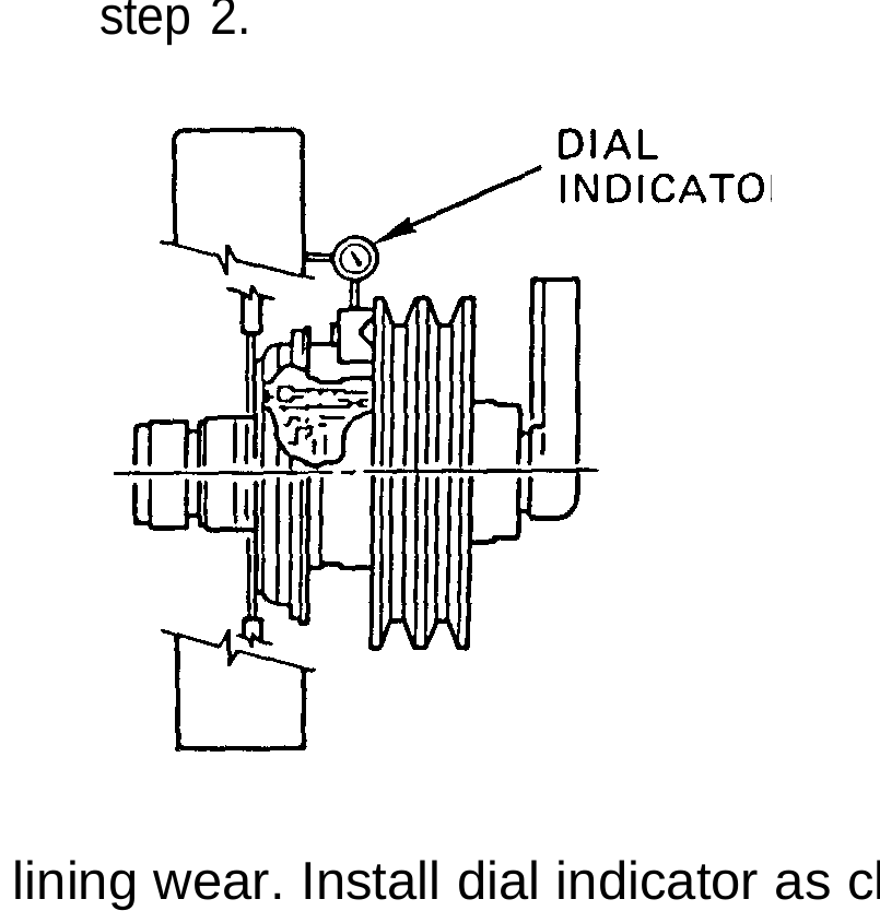
Table 2-1. Troubleshooting (Cont) Malfunction Test or Inspection Corrective Action
ENGINE (CONT)
3. ENGINE RUNS ERRATICALLY.
Step 1. Inspect timing wheel for looseness. Tighten timing wheel (page 12-41).
Step 2. Inspect timing wheel for chipped or missing teeth. Replace timing wheel (page 12-41).
4. ENGINE OVERHEATS.
Step 1. Check for excessive fan tip movement (wobble). Measure movement with fan disengaged. Movement must not exceed 3/16 in. (4.76 mm) fore and aft at blade tip. If measurement exceeds 3/16 in. (4.76 mm), replace clutch (TM 9-2320-363-20). If measurement is within tolerance, go to step 2.
Step 2. Check for lining wear. Install dial indicator as close to clutch as possible and place indicator probe on clutch. Apply air pressure of at ieast 90 psi (620.5 kPa). Make sure fan rotates freely. Zero indicator and release pressure and disconnect tube. If dial indicator reads 0.17 in. (4.32 mm) or greater, repair (page 12-206) or replace clutch (TM 9-2320-363-20).
5. ENGINE RETARDER (JAKE BRAKE) NOT OPERATING.
Test retarder solenoid (page 4-50). Replace retarder solenoid (page 4-50).
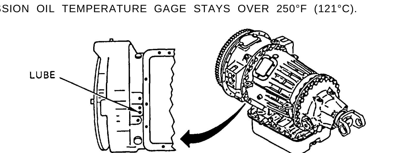
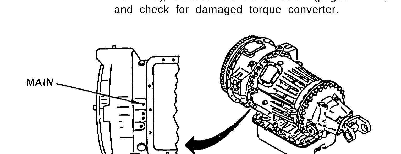
Table 2-1. Troubleshooting (Cont) Malfunction Test or lnspection Corrective Action
To make a thorough test of vehicle-mounted transmission, be sure engine is properly tuned and oil level in transmission is correct.
TRANSMISSION
1. TRANSMISSION OIL TEMPERATURE GAGE STAYS OVER 250°F (121°C).
Step 1. Check for low lubrication oil pressure. Remove plug from lube port and install 0 to 100 psi (0 to 690 kPa) gage. Start engine and allow to run at idle speed. With parking brake applied, shift transmission into DRIVE and accelerate engine to approximately 1900 rpm. Check for 25 to 30 psi (172 to 207 kPa) lube system pressure. l If pressure is less than 25 or more than 30 psi (172 to 207 kPa), disassemble transmission (pages 14-22, 14-27, 14-35) and check for damaged torque converter.
Step 2. Check for low main pressure. Remove oil line (all except M915A2) or plug (M915A2) from main pressure port on transmission and install tee (all except M915A2) and 0 to 300 psi (0 to 2070 kPa) gage. Start engine and allow to run at idle speed (600 rpm). With parking brake applied, shift transmission into DRIVE. Check for 80 to 100 psi (552 to 690 kPa) main system pressure. l If pressure is not 80 to 100 psi (552 to 690 kPa), disassemble transmission (page 14-27) and inspect lubrication pressure regulator and converter bypass valve for damage.
Change 1 2-7
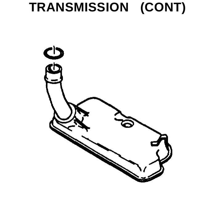
Table 2-1. Troubleshooting (Cont) Malfunction Test or Inspection Corrective Action
TRANSMISSION (CONT)
Step 3. Check for clogged internal filter element. Remove internal filter element (page 3-258). l It internal filter element is clogged, replace internal filter element (page 3-258) and repeat step 2.
Step 4. Check for damaged or missing preformed packing on internal filter pickup tube. l If preformed packing is damaged or missing, replace preformed packing (page 3-258) and repeat step 2. l If preformed packing is not damaged or missing, disassemble transmission (page 14-1) and inspect oil pump, main pressure regulator valve, and control valve body for loose screws and sticking valves. Repeat step 2.
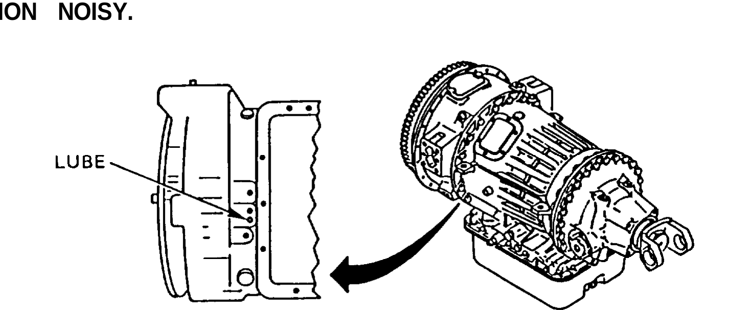
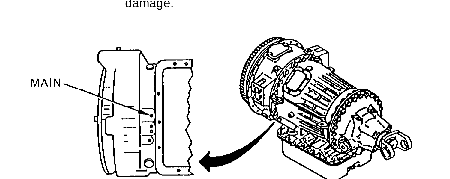
Table 2-1. Troubleshooting (Cont) Malfunction Test or lnspection Corrective Action
TRANSMISSION (CONT)
2. TRANSMISSION NOISY.
Step 1. Check for low lubrication oil pressure. Remove plug from lube port. Install 0 to 100 psi (0 to 690 kPa) gage. Start engine and allow to run at idle speed. With parking brake applied, shift transmission into DRIVE and accelerate engine to approximately 1900 rpm. Check for 25 to 30 psi (172 to 207 kPa) lube system pressure. If pressure is less than 25 or more than 30 psi (172 to 207 kPa), disassemble transmission (page 14-1) and check torque converter, planetary gear assemblies, and bearings for damage.
Step 2. Check for low main pressure. Remove oil line (all except M915A2) or plug (M915A2) from main pressure port on transmission and install tee (all except M915A2) and 0 to 300 psi (0 to 2070 kPa) gage. Start engine and allow to run at idle speed (600 rpm). With parking brake applied, shift transmission into DRIVE. Check for 80 to 100 psi (552 to 690 kPa) main system pressure. l If pressure is less than 80 or more than 100 psi (552 to 690 kPa), disassemble transmission (page 14-27) and inspect lubrication pressure regulator and converter bypass valve for damage. Inspect all other moving parts for damage from lack of oil.
Change 1 2-9
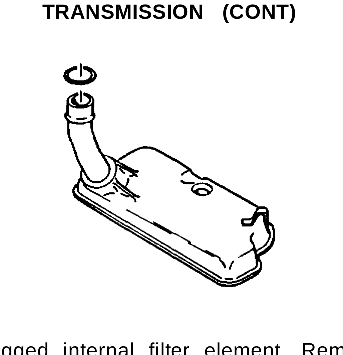
Table 2-1. Troubleshooting (Cont) Malfunction Test or lnspection Corrective Action
TRANSMISSION (CONT)
Step 3. Check for clogged internal filter element. Remove internal filter element (page 3-258). If internal filter element is clogged, replace internal filter element (page 3-258) and repeat step 2. If filter element is not clogged, check for damaged or missing preformed packing on pickup tube. Replace damaged or missing preformed packing (page 3-258) and repeat step 2. If transmission is still noisy, disassemble transmission (page 14-27) and inspect oil pump, main pressure regulator valve, converter bypass valve, and lubrication pressure regulator for damage. Inspect all other parts for damage from lack of oil.
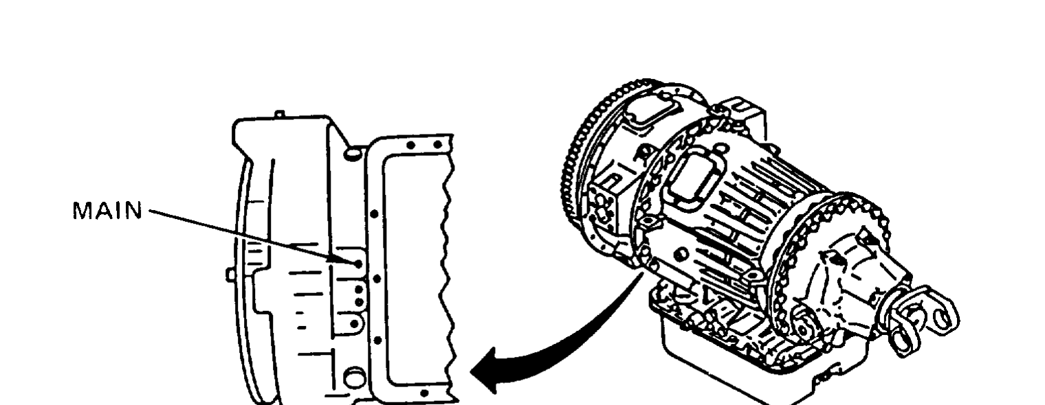
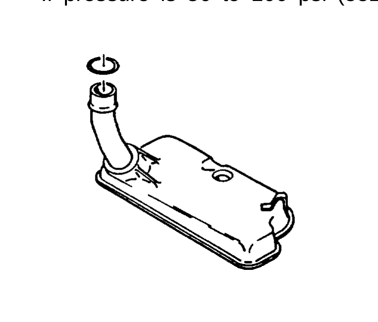
Table 2-1. Troubleshooting (Cont) Malfunction Test or lnspection Corrective Action
TRANSMISSION (CONT)
3. TRANSMISSION WILL NOT SHIFT INTO GEAR, SLIPS OUT OF GEAR, OR OPERATES ERRATICALLY.
Step 1. Check for low main pressure. Remove oil line (all except M915A2) or plug (M915A2) from main pressure port on transmission and install tee (all except M915A2) and 0 to 300 psi (0 to 2070 kPa) gage. Start engine and allow to run at idle speed (600 rpm). With parking brake applied, shift transmission into DRIVE. Check for 80 to 100 psi (552 to 690 kPa) main system pressure. l If pressure is 80 to 100 psi (552 to 690 kPa), go to step 4.
Step 2. Check for clogged internal filter element. Remove oil pan (TM 9-2320-363-20). l If internal filter element is clogged, replace internal filter element (page 3-258) and repeat step 1.
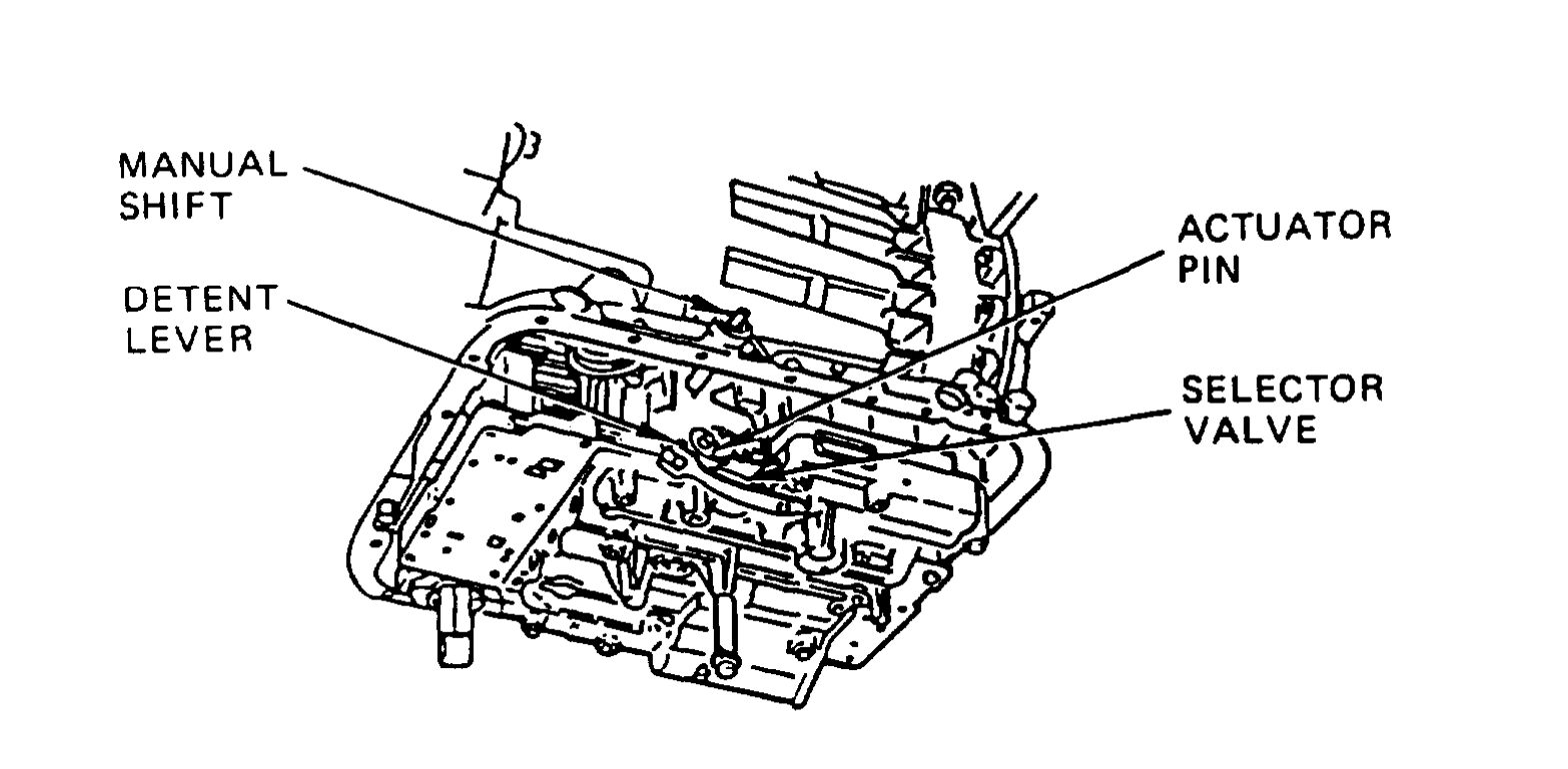
Table 2-1. Troubleshooting (Cont) Malfunction Test or Inspection Corrective Action
TRANSMISSION (CONT)
Step 3. Check for damaged or missing preformed packing on internal filter pickup tube. l If preformed packing is damaged or missing, replace preformed packing and gasket (page 3-258) and repeat step 1. l If preformed packing is not damaged or missing, disassemble transmission (page 14-1) and inspect oil pump, main pressure regulator valve, and control valve body for loose screws and sticking valves.
Step 4. Remove oil pan (TM 9-2320-363-20). Manually shift transmission and check that manual shaft and detent lever engage selector valve and that actuator pin is attached to detent lever. l If selector valve does not engage detent lever, repair selector valve (page 14-74) or replace defective parts (TM 9-2320-363-20). l If selector valve engages, disassemble transmission (page 14-1) and valve body (page 14-74) and check for worn clutch packs in transmission, loose valve body screws, and sticking valves in valve body.
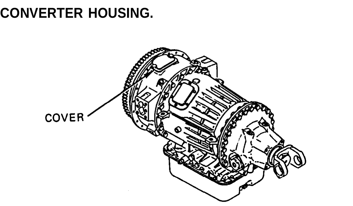
Table 2-1. Troubleshooting (Cont) Malfunction Test or Inspection Corrective Action
TRANSMISSION (CONT)
4. OIL LEAKING AT CONVERTER HOUSING.
Remove cover from top of converter housing (page 14-7). Check for signs of oil. If engine oil is inside housing, replace rear engine crankshaft oil seaI (pages 3-141, 3-145). If transmission oil is inside housing, inspect inner converter housing mounting screws, converter pump to converter housing seal ring, converter housing gasket, torque converter cover seal ring, oil pump seal, pitot attachment screws, pump hub seal rings, and converter pump hub.
5. EXCESSIVE CREEP IN FIRST AND REVERSE.
Step 1. Check for too high engine speed. If idle is more than 600 rpm, adjust engine idle speed (TM 9-2320-363-20).
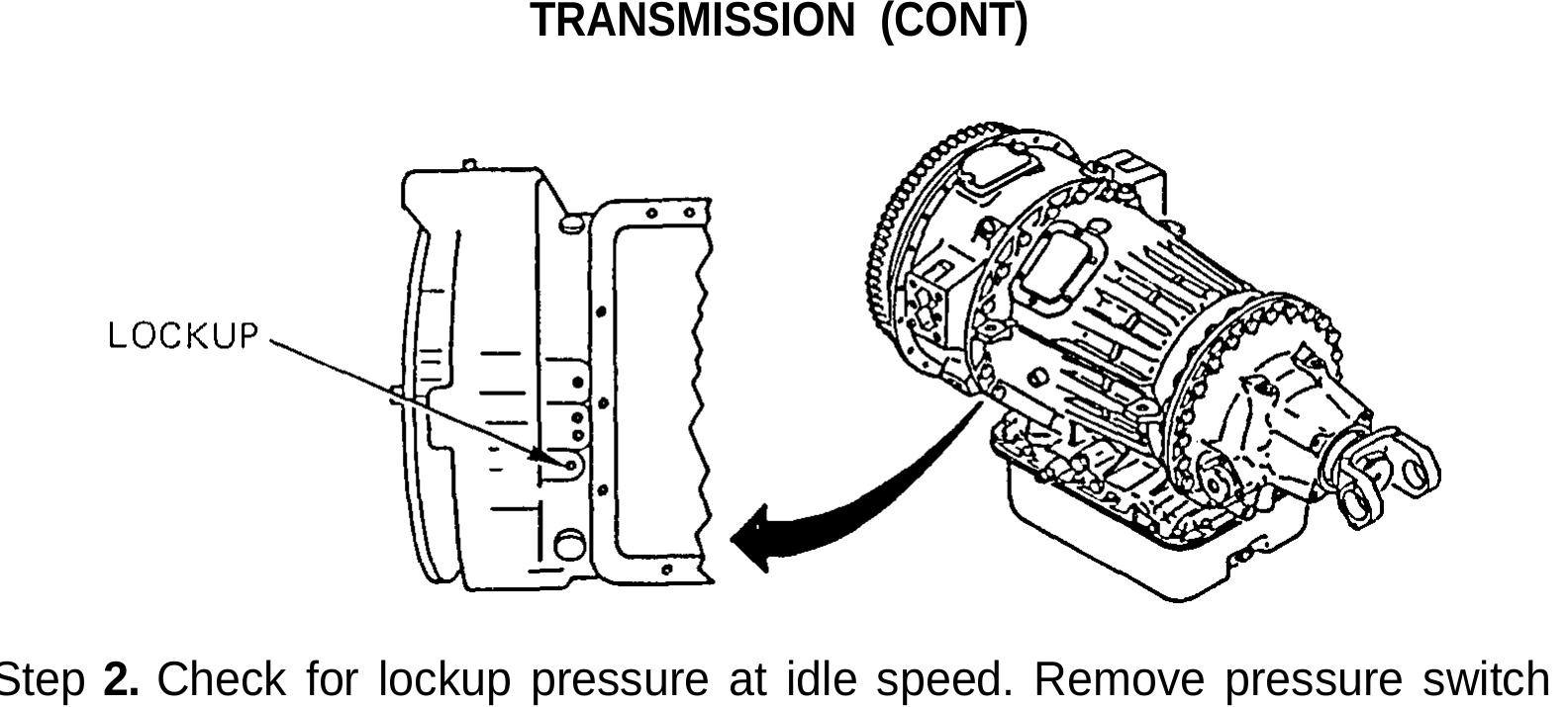
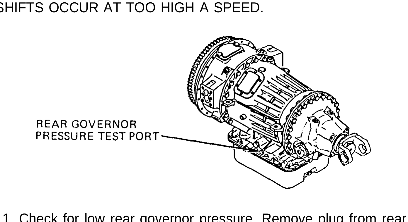
Table 2-1. Troubleshooting (Cont) Malfunction Test or inspection Corrective Action
TRANSMISSION (CONT)
Step 2. Check for lockup pressure at idle speed. Remove pressure switch at transmission lockup port and install tee and 0 to 300 psi (0 to 2070 kPa) gage. Start engine and allow to run at idle speed. With parking brake applied, shift transmission into DRIVE. Check for 0 psi (0 kPa) lockup pressure. There should be no lockup pressure. If there is any lockup pressure, inspect lockup clutch valve for sticking pistons (page 3-262). If there is no lockup pressure, disassemble transmission (page 14-1 ) and check for warped clutch plates, stuck (applied) clutch pack pistons, or damaged torque converter to turbine support bearing.
6. AUTOMATIC SHIFTS OCCUR AT TOO HIGH A SPEED.
Step 1. Check for low rear governor pressure. Remove plug from rear governor test port. install 0 to 200 psi (0 to 1380 kPa) gage at rear governor test port. Start engine and shift transmission into DRIVE. Release parking brake and drive vehicle until engine tachometer reads approximately 1650 rpm. Check for 100 to 115 psi (690 to 794 kPa) rear governor pressure. If pressure is below 100 psi (690 kPa), repair valve body (page 14-74).
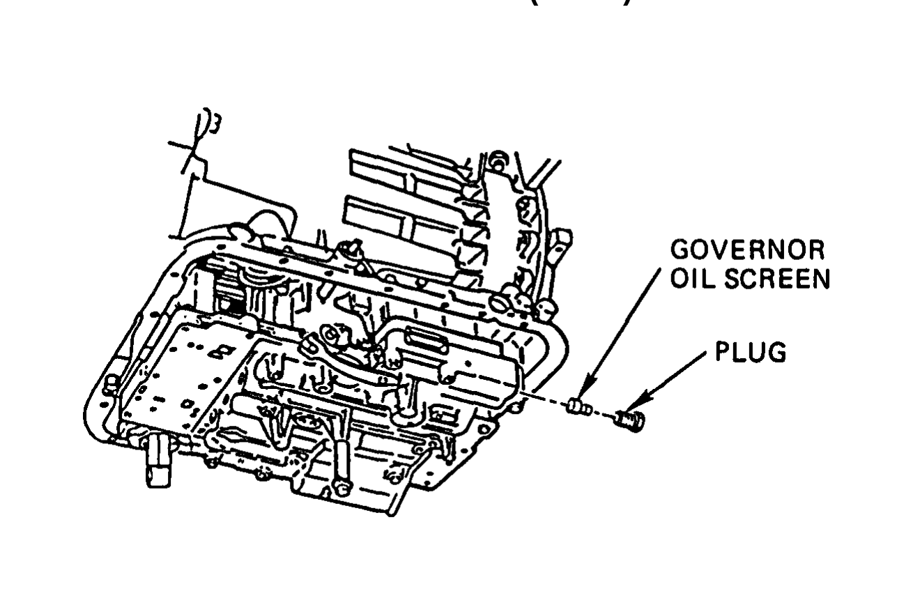
Table 2-1. Troubleshooting (Cont) Malfunction Test or Inspection Corrective Action
TRANSMISSION (CONT)
Step 2. Check for clogged governor oil filter screen. Remove oil pan (TM 9-2320-363-20), Remove plug and oil filter screen (page 3-260). If oil filter screen is clogged or damaged, clean or replace oil filter screen as required (page 3-260) and repeat step 1. If oil filter screen is not clogged or damaged, go to Malfunction 3, steps 1 thru 3.
7. AUTOMATIC SHIFTS OCCUR AT TOO LOW A SPEED, OR SHIFTS ROUGH.
Step 1. Check for defective modulator valve, Remove modulator valve from transmission (TM 9-2320-363-20), Apply 70 psi (483 kPa) air pressure at modulator valve hose fitting. Check that modulator valve plunger moves as air is applied. Modulator valve must not leak air when operated. If modulator valve does not operate properly or is damaged, replace modulator valve (TM 9-2320-363-20).
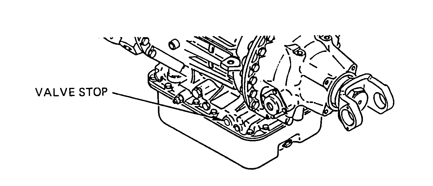
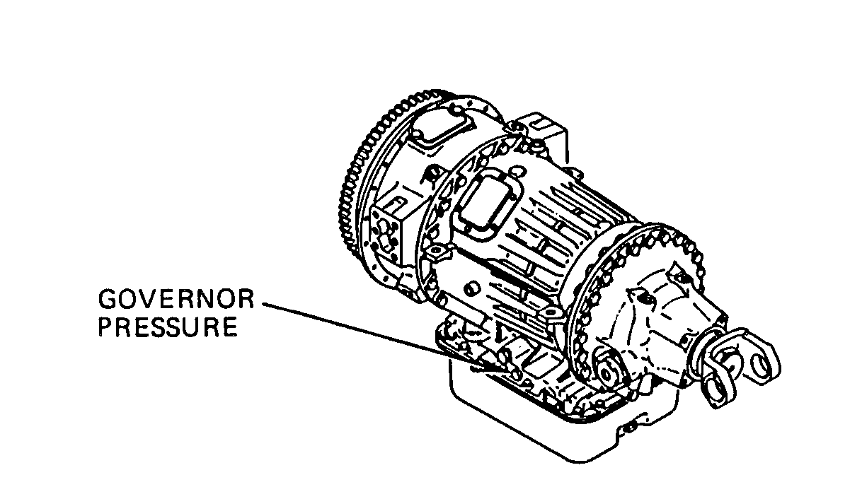
Table 2-1. Troubleshooting (Cont) Malfunction Test or Inspection Corrective Action
TRANSMISSION (CONT)
Step 2. Check for defective control valve. Remove modulator valve from transmission (page 3-261 ). Check valve stop in transmission for free movement. Check that spring pushes valve stop out when released and is not damaged. If valve stop does not move freely or spring is damaged or does not push valve stop out, repair control valve (page 14-74).
Step 3. Check for high rear governor pressure. Remove plug from rear governor test port. Install 0 to 200 psi (0 to 380 kPa) gage at rear governor test port. Start engine and shift transmission into DRIVE. Release parking brake and drive vehicle until engine tachometer reads approximately 1650 rpm. Check for 100 to 115 psi (690 to 794 kPa) rear governor pressure. If pressure is over 115 psi (794 kPa), replace governor valve (page 3-260). If pressure is below 100 psi (690 kPa), repair control valve body (page 14-74).
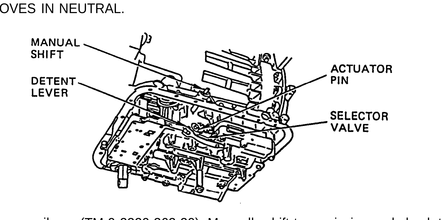
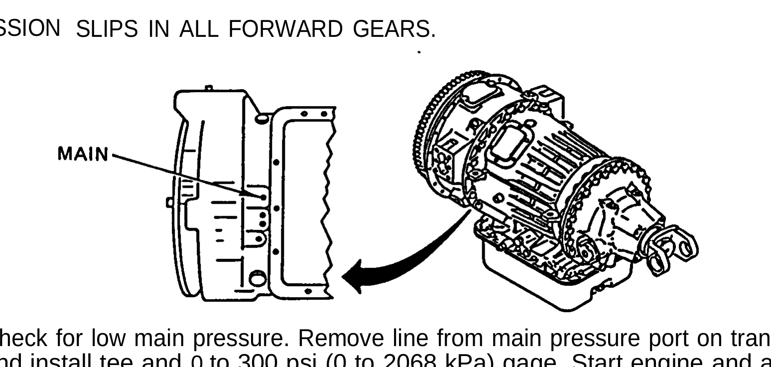
Table 2-1. Troubleshooting (Cont) Malfunction Test or inspection Corrective Action
TRANSMISSION (CONT)
8. VEHICLE MOVES IN NEUTRAL.
Remove oil pan (TM 9-2320-363-20). Manually shift transmission and check that manual shaft and detent lever engage selector valve and that actuator pin is attached to detent lever. If selector valve does not engage detent lever, replace defective parts (TM 9-2320-363-20). If selector valve engages, disassemble transmission (page 14-1) and valve body (page 14-74) and check for applied clutch packs in transmission or leaking or sticking valves in valve body.
9. TRANSMISSION SLIPS IN ALL FORWARD GEARS.
Check for low main pressure. Remove line from main pressure port on transmission and install tee and 0 to 300 psi (0 to 2068 kPa) gage. Start engine and allow to run at idle speed. With parking brake applied, shift transmission into DRIVE. Check for 80 to 100 psi (552 to 690 kPa) main system pressure. If pressure is 80 to 100 psi (552 to 690 kPa), rebuild forward clutch (page 14-54). If pressure is less than 80 psi (552 kPa), go to Malfunction 3, steps 1 thru 3.
TM 9-2320 -363-34-1
Table 2-1. Troubleshooting (Cont) Malfunction Test or inspection Corrective Action
TRANSMISSION (CONT)
10. HIGH STALL SPEED (ABOVE 1200 RPM).
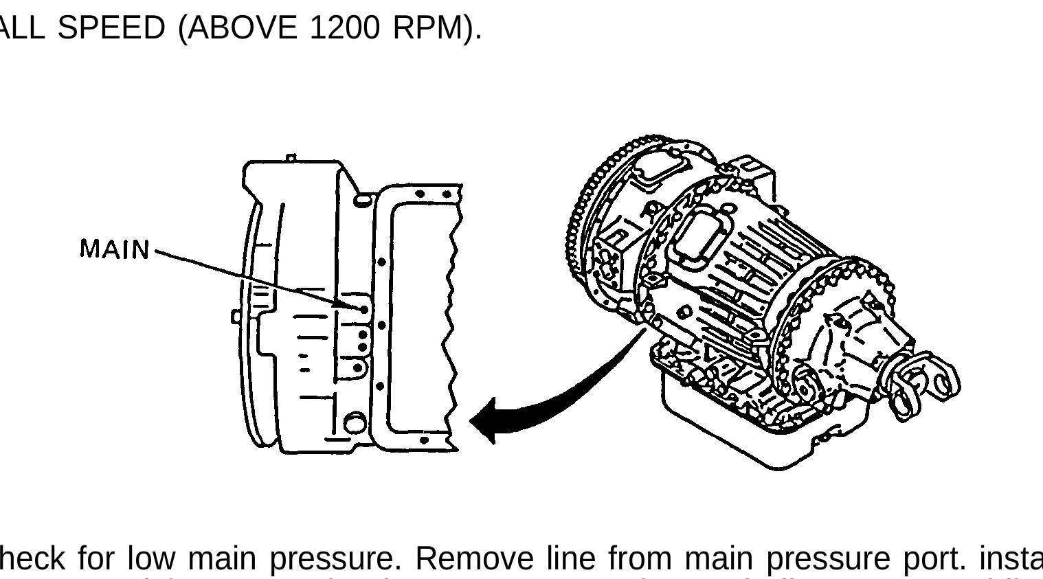
Check for low main pressure. Remove line from main pressure port. install tee and 0 to 300 psi (0 to 2070 kPa) gage. Start engine and allow to run at idle speed. With parking brake applied, shift transmission into DRIVE and accelerate engine to approximateiy 1200 rpm. Check for 140 to 175 psi (965 to 1206 kPa) main system pressure. If pressure is 140 to 175 psi (965 to 1206 kPa), disassemble transmission (page 14-54) and inspect forward and first clutches for damage. If pressure is not 140 to 175 psi (965 to 1206 kPa), go to Malfunction 2.
11. LOW STALL SPEED (BELOW 1100 RPM).
Check for damaged torque converter. Disassemble torque converter stator, pump, and housing (pages 14-22, 14-27, 14-35). Replace damaged torque converter parts (pages 14-22, 14-27, 14-35).
Table 2-1. Troubleshooting (Cont) Malfunction Test or lnspection Corrective Action
TRANSFER CASE (ALL EXCEPT M915A2)
1. TRANSFER CASE WILL NOT ENGAGE, SHIFT CONTROL CABLE AND LINKAGE IS OPERATIVE.
Check for internal binding or broken linkage. l Repair (page 15-2) or replace transfer case (page 3-234).
2. TRANSFER CASE WILL NOT ENGAGE IN HIGH RANGE, LOW RANGE IS OPERATIVE, SHIFT CONTROL CABLE AND LINKAGE IS OPERATING.
Check for binding or broken high range-shaft or gears. l Repair (page 15-2) or replace transfer case (page 3-234).
3. TRANSFER CASE WILL NOT ENGAGE IN LOW RANGE, HIGH RANGE IS OPERATIVE, SHIFT CONTROL CABLE AND LINKAGE IS OPERATING.
Check for binding or broken low-range shaft or gears. l Repair (page 15-2) or replace transfer case (page 3-234).
4. TRANSFER CASE OVERHEATS DURING OPERATION, LUBRICATION AT PROPER LEVEL.
Check for failed bearings. l Repair (page 15-2) or replace transfer case (page 3-234).
5. TRANSFER CASE EXCESSIVELY NOISY.
Step 1. Check for proper oil level. l Service transfer case (TM 9-2320-363-20).
Step 2. Check for worn bearings and gears. l Repair (page 15-2) or replace transfer case (page 3-234).
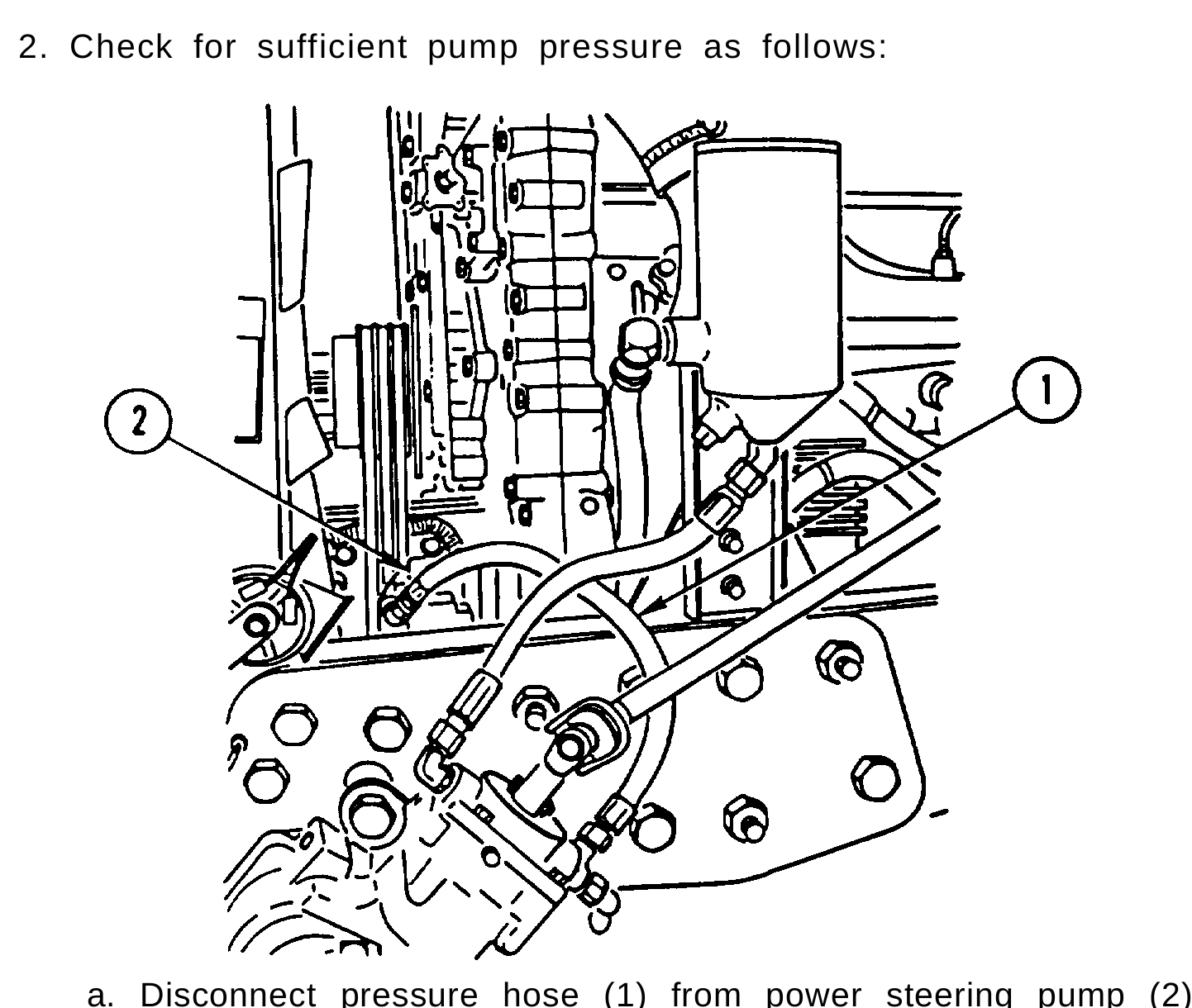
Table 3-1. Troubleshooting (Cont) Malfunction Test or Inspection Corrective Action
STEERING
1. ABNORMAL NOISE.
Step 1. If clicking noise is heard when initiating steering maneuver or when changing directions of turn, some linkage component is probably loose and shifting under load. l Tighten or replace loose or defective components,
Step 2. Check for excessive air in fluid (fluid is foamy) and/or low fluid level.
I l Fill pump reservoir to proper level (TM 9-2320-363-20).
2. NO RECOVERY.
Step 1. Disconnect lower steering column from steering gear and check both upper and lower columns for binding. l Replace defective column or universal joint (TM 9-2320-363-20).
Step 2. Check for sufficient pump pressure as follows:
a. Disconnect pressure hose (1) from power steering pump (2).
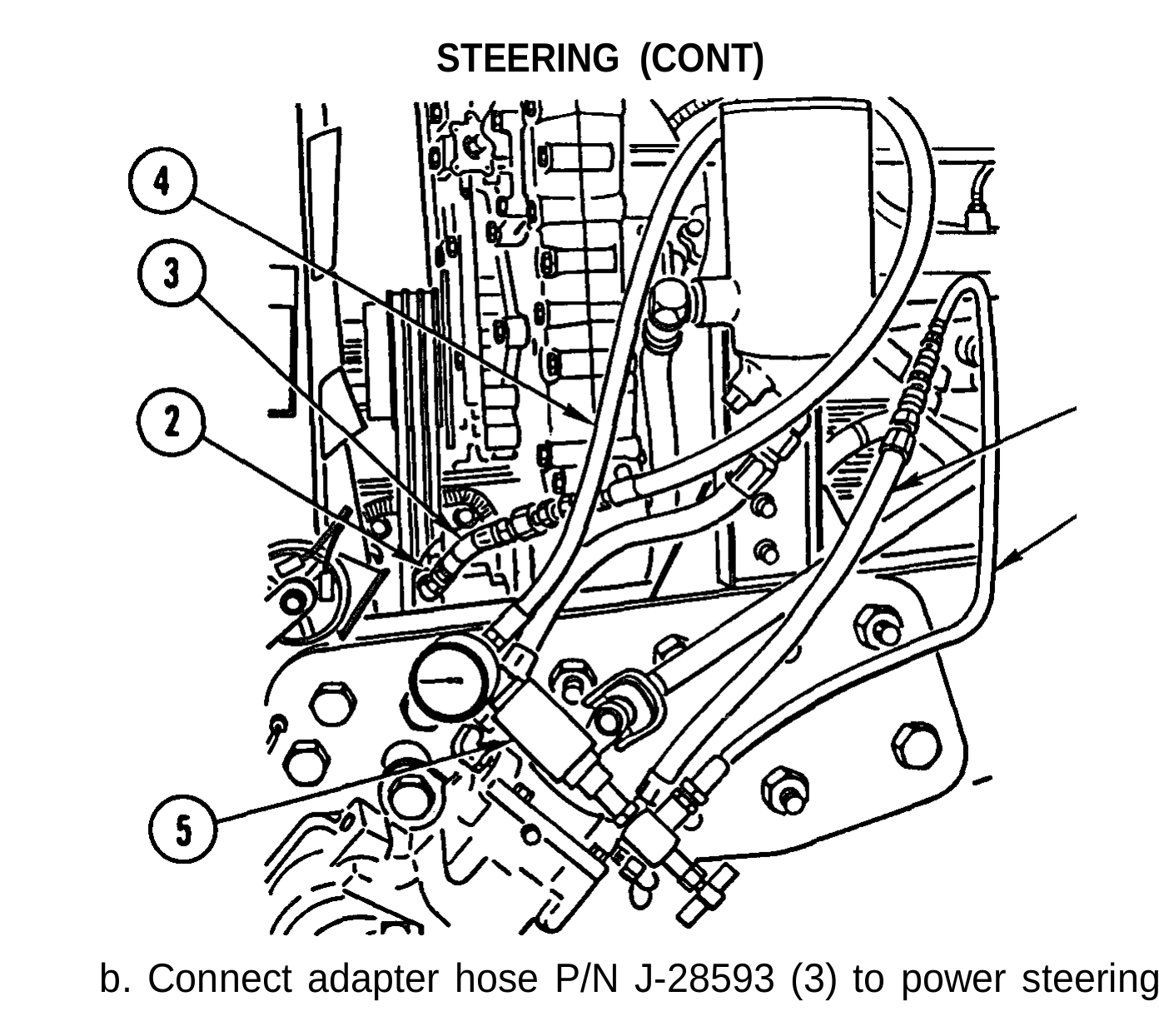
Table 2-1. Troubleshooting (Cont) Malfunction Test or Inspection Corrective Action
STEERING (CONT)
b. Connect adapter hose P/N J-28593 (3) to power steering pump (2).
c. Connect hose (4) from dial end of flow/pressure tester P/N J-26487-B (5) to adapter hose (3).
d. Connect hose (6) from load valve end of flow/pressure tester (5) to pressure hose (1).
Before performing step e, make sure load valve is completely open to prevent damage to flow/pressure valve.
e. With engine idling, rotate steering wheel to left and right for 5 minutes to warm power steering fluid.
Table 2-1. Troubleshooting (Cont) Malfunction Test or Inspection Corrective Action
STEERING (CONT)
To prevent damage to power steering pump during performance of step f, do not allow load valve to be closed for more than 5 seconds.
f. With engine idling, close load valve and read pressure gage. Pressure must be 900 to 1000 psi (621 to 690 kPa). If pressure is less than 900 psi (621 kPa), repair (page 19-2) or replace power steering pump (page 7-2).
Step 3. Check for sufficient pump flow as follows:
a. Perform steps a thru e of step 2.
Maximum flow rate is 7 gpm (26.5 liters/rein). Flow rate in excess of 7 gpm (26.5 liters/rein) will damage steering gear and could cause loss of steering and injury to personnel.
b. With engine idling, read flow meter. Rate of flow must be 7 gpm (26.5 liters/rein). Repair (page 19-2) or replace power steering pump (page 7-2).
c. With engine idling, close load valve until pressure gage indicates pump relief and pump relief pressure drops to 0. Immediately open load valve. Flow rate must return to 7 gpm (26.5 liters/rein). Repair (page 19-2) or replace power steering pump (page 7-2).
d. Run engine at 2100 rpm and fully close load valve until pressure gage indicates pump relief and flow rate drops to 0. Immediately open load valve. Flow rate must return to 7 gpm (26.5 liters/rein). Repair (page 19-2) or replace power steering pump (page 7-2).
Step 4. Check for defective teflon seals in steering control valve. Repair (page 19-8) or replace steering gear (page 7-4).
Table 3-1. Troubleshooting (Cont) Malfunction Test or Inspection Corrective Action
STEERING (CONT)
Step 5. Check for steering gear control valve sticking. l Repair (page 19-8) or replace steering gear (page 7-4).
3. EXTERNAL OIL LEAKS FROM STEERING GEAR.
Step 1. Check for leak at rubber relief plug (on frame side of steering gear). l Repair (page 19-8) or replace steering gear (page 7-4).
Step 2. Check for leak at shaft seals. l Repair (page 19-8) or replace steering gear (page 7-4).
4. OVERSTEER OR DARTING.
Step 1. Disconnect lower steering column from steering gear and check both upper and lower columns for binding. l Replace defective column or universal joint (TM 9-2320-363-20).
Step 2. Disconnect steering gear pitman arm and check front end components for binding. l Replace defective components (TM 9-2320-363-20).
5. HIGH STEERING EFFORT IN ONE DIRECTION.
Step 1. Check for sufficient pump pressure (Malfunction 2, step 2). l If pressure is less than 900 psi (621 kPa), repair (page 19-2) or replace power steering pump (page 7-2).
Step 2. Check for sufficient pump flow (Malfunction 2, step 3). l Repair (page 19-2) or replace power steering pump (page 7-2).
Step 3. Check for defective teflon seals in steering control valve. l Repair (page 19-8) or replace steering gear (page 7-4).
Step 4. Check for steering gear control valve sticking. l Repair (page 19-8) or replace steering gear (page 7-4).
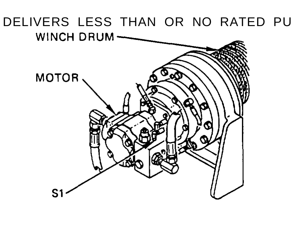
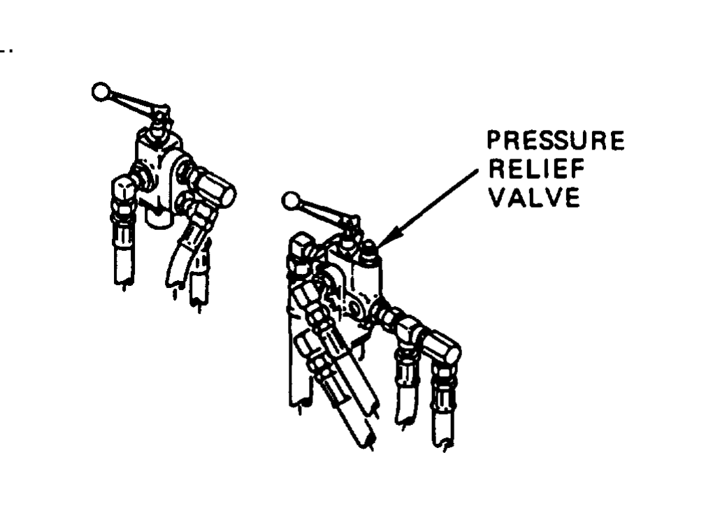
Table 3-1. Troubleshooting (Cont) Malfunction Test or Inspection Corrective Action
STEERING (CONT)
6. HIGH STEERING EFFORT IN BOTH DIRECTIONS.
Step 1. Disconnect lower steering column from steering gear and check both upper and lower columns for binding. l Replace defective column or universal joint (TM 9-2320-363-20).
Step 2. Disconnect steering gear pitman arm and check front end components for binding. l Replace defective components (TM 9-2320-363-20).
Step 3. Check for sufficient pump pressure (Malfunction 2, step 2). l If pressure is less than 900 psi (621 kPa), repair (page 19-2) or replace power steering pump (page 7-2).
Step 4. Check for sufficient pump flow (Malfunction 2, step 3). l Repair (page 19-2) or replace power steering pump (page 7-2).
HYDRAULIC WINCH (M916A1 AND M916A2)
1. NO OR LOW OIL FLOW FROM PUMP.
Check for broken input shaft and internal parts. l Repair (page 23-12) or replace winch hydraulic pump (page 11-2).
2. EXTERNAL LEAKS.
Check for damaged packings. l Replace damaged packings (pages 23-9, 23-12).
3. DELIVERS LESS THAN OR NO RATED PULL.
Table 2-1. Troubleshooting (Cont) Malfunction Test or lnspection Corrective Action
HYDRAULIC WINCH (M916A1 AND M916A2 (CONT)
Check pressure relief valve setting. Install pressure gage with capacity of 3000 psi (20695 kPa) in brake pilot line and plug port S1 in counterbalance manifold. Apply hydraulic power, run engine at 1000 rpm, and observe pressure on gage.
To prevent damage to equipment, do not try to adjust counterbalance valve. It is a sealed non-adjustable unit.
l If pressure is less than 2500 ±50 psi (17250 ±345 kPa), replace relief valve on control valve (page 23-22). l If pressure is normal, replace hydraulic motor (page 11-15).
4. DOES NOT HOLD LINE IN NEUTRAL.
Step 1. Check for damaged packings. l Replace damaged packings (pages 23-9, 23-12).
Step 2. Check for damaged or broken brake springs. l Repair winch brake (page 23-34).
Step 3. Check for damaged or worn friction plates. l Repair winch brake (page 23-34).
5. BRAKE WILL NOT RELEASE.
Step 1. Check for leaking packings and connections. l Replace leaking motor packings (page 23-9) pump packings (page 23-12) and tighten loose connections. If problem still exists, go to step 2.
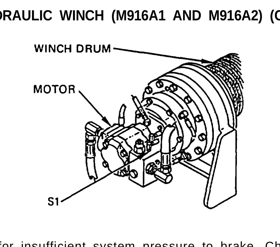
Table 3-1. Troubleshooting (Cont) Malfunction Test or lnspection Corrective Action
HYDRAULIC WINCH (M916A1 AND M916A2) (CONT)
Step 2. Check for insufficient system pressure to brake. Check hydraulic system pressure. Install pressure gage with capacity of 3000 psi (20685 kPa) in brake pilot line and plug port S1 in counterbalance manifold. Apply hydraulic power, run engine at 1000 rpm, and observe pressure on gage. l If pressure is below 270 psi (1861 kPa), repair (page 23-12) or replace hydraulic pump (page 11-2). l If pressure is at least 270 psi (1861 kPa), check for jammed gearing in winch, or repair brake (pages 23-2, 23-26, 23-34).
6. BRAKE WILL NOT APPLY. OR APPLIES BUT TORQUE LOW.
Check for damaged springs or friction plates. l Repair (page 23-9) or replace hydraulic motor (page 11-15).
ARCTIC HEATER
1. HEATER WILL NOT START, BLOWER DOES NOT RUN.
Step 1. Check for damaged wiring. l Repair (page 25-34) or replace wiring (page 25-34).
Step 2. Check for defective blower motor. l Replace blower motor (page 25-26).
2. BLOWER RUNS WHEN SWITCH IS IN START POSITION, BUT HEATER WILL NOT IGNITE.
Step 1. Check for defective flame detector switch. l Replace flame detector switch (page 25-30).
Table 3-1. Troubleshooting (Cont) Malfunction Test or InspectIon Corrective Action
ARCTIC HEATER (CONT)
Step 2. Check for defective fuel control valve. Replace fuel control valve (page 25-14). Step 3. Check for defective thermostat, Replace thermostat switch (page 25-18). Step 4. Check for defective fixed resistor. Replace fixed resistor (page 25-22).
3. BLOWER RUNS WHEN SWITCH IS IN START POSITION AND HEATER IGNITES, BUT PILOT LAMP WILL NOT LIGHT.
Check for defective flame detector switch. Reset, or replace flame detector switch (page 25-30).
4. HEATER STARTS AND RUNS BUT GOES OUT LATER.
Step 1. Check for restriction in coolant flow. Clear restriction from hose(s) (TM 9-2320-363-20). Step 2. Check for defective thermostat. Replace thermostat (page 25-28). Step 3. Check for defective fuel control valve. Replace fuel control valve (page 25-14).
5. HEATER OVERHEATS. Step 1. Check for defective fuel control valve. Replace fuel control valve (page 25-14). Step 2. Check for defective thermostat. Replace thermostat (page 25-28). Step 3. Check for restriction in coolant flow. Clear restriction from hose(s) (TM 9-2320-363-20).
6. HEAT OUTPUT LOW. Step 1. Check for defective fuel control valve. Replace fuel control valve (page 25-14).
Table 3-1. Troubleshooting (Cont) Malfunction Test or Inspection Corrective ActIon
ARCTIC HEATER (CONT)
Step 2. Check for defective thermostat. Replace thermostat (page 25-28).
7. HEATER BURNS ON HIGH HEAT CONTINUOUSLY.
Check for defective diode. Replace diode (page 25-11).
8. HEATER BURNS ON LOW HEAT CONTINUOUSLY. Step 1. Check for defective thermostat. Replace thermostat (page 25-28).
Step 2. Check for defective diode. Replace diode (page 25-11).
9. HEATER SMOKES EXCESSIVELY.
Step 1. Check for leaking fuel control valve. Replace fuel control valve (page 25-14).
Step 2. Check for restriction in exhaust system. Clean exhaust system.
Step 3. Check for low voltage at batteries. Replace batteries (TM 9-2320-363-20).
10. BLOWER WILL NOT STOP WHEN HEATER IS SHUT OFF.
Check for defective flame detector switch. Replace flame detector switch (page 25-30).