Cab Door Replacement
TM 9-2320-363-34-1 · Chapter 10 — Body, Cab, Hood, and Hull Maintenance
This task covers: a. Removal b. Cleaning c. Inspection d. Installation
Tools and Special Equipment:                      Equipment Condition:
Tool Kit, SC 5180-90-CL-N05                       Reference                Condition Description
Materials/Parts:                                  TM 9-2320-363-20         Rear View Mirror
                                                                           Removed
Tape, Foam                P/N 4800050208
                                                  General Safety Instructions:
Personnel Required: (2)
References:                                                       WARNING
TM 9-2320-363-20                                         Due to size of door and angle
                                                         for removal or installation, use
                                                         minimum of two personnel to
                                                         remove or install door, Failure
                                                         to do so could result in injury
                                                         to personnel.
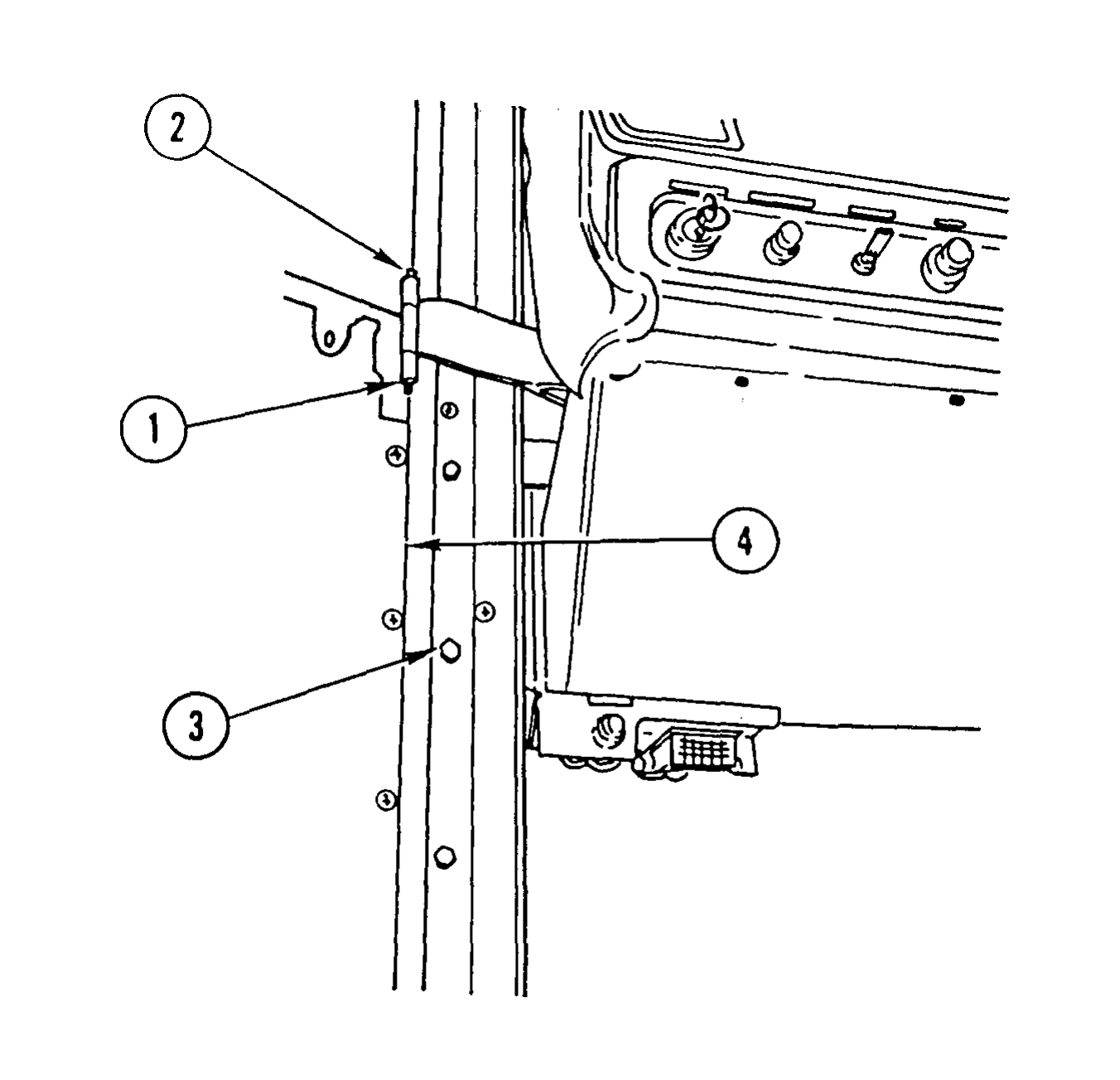
1. REMOVE CAP NUT (1) AND SOCKET HEAD SCREW (2).
2. REMOVE EIGHT CAPSCREWS (3) AND DOOR (4).
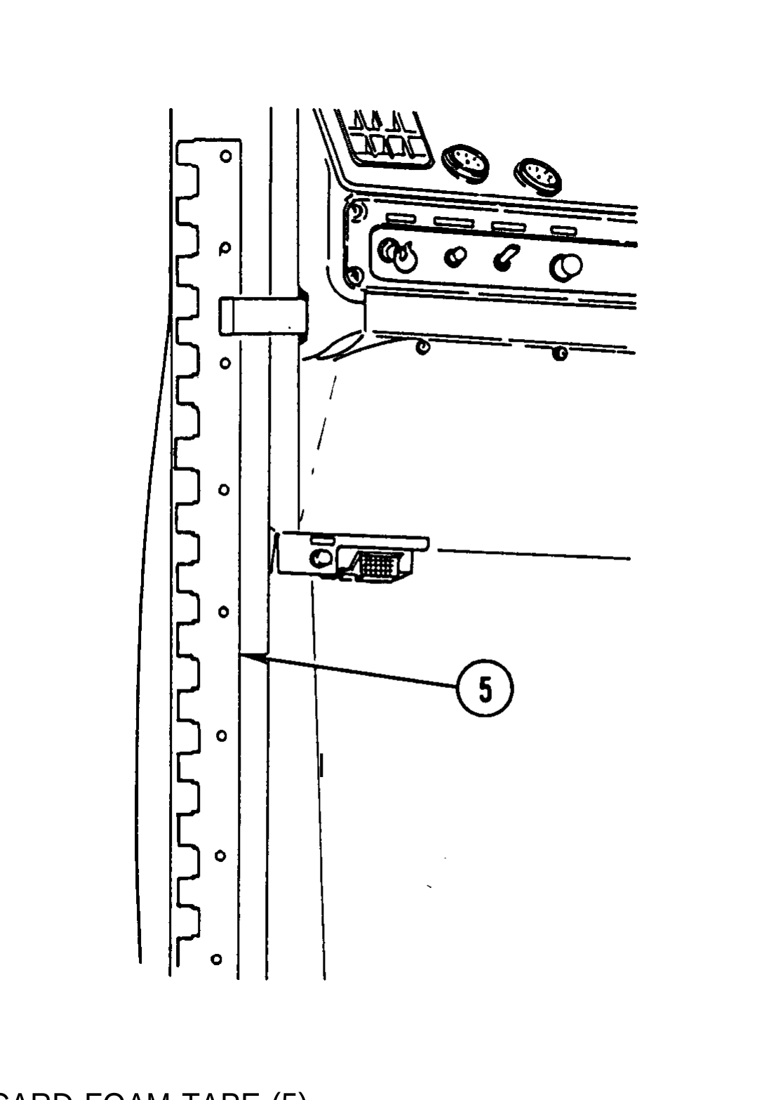
I
3. REMOVE AND DISCARD FOAM TAPE (5).
Use general cleaning methods to clean all parts (page 2-30).
1. INSPECT DOOR SEALS AND WINDOW CHANNELS FOR DAMAGE.
2. INSPECT DOOR LOCKS, REGULATORS, AND RELEASE HANDLES FOR PROPER OPERATION. IF DAMAGED, REFER TO DOOR REPAIR (PAGE 22-28).
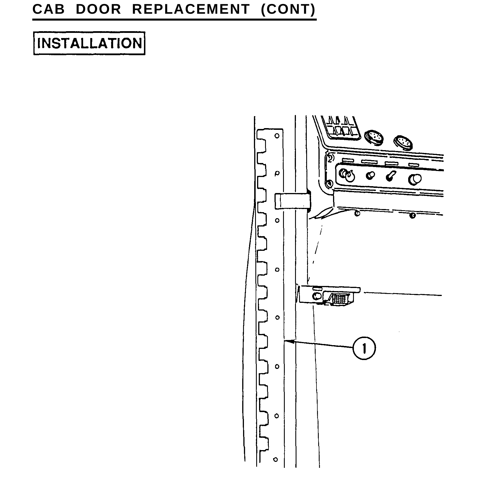
1. INSTALL NEW FOAM TAPE (1) AND, USING SHARP IMPLEMENT, CUT HOLES FOR CAPSCREW INSTALLATION.
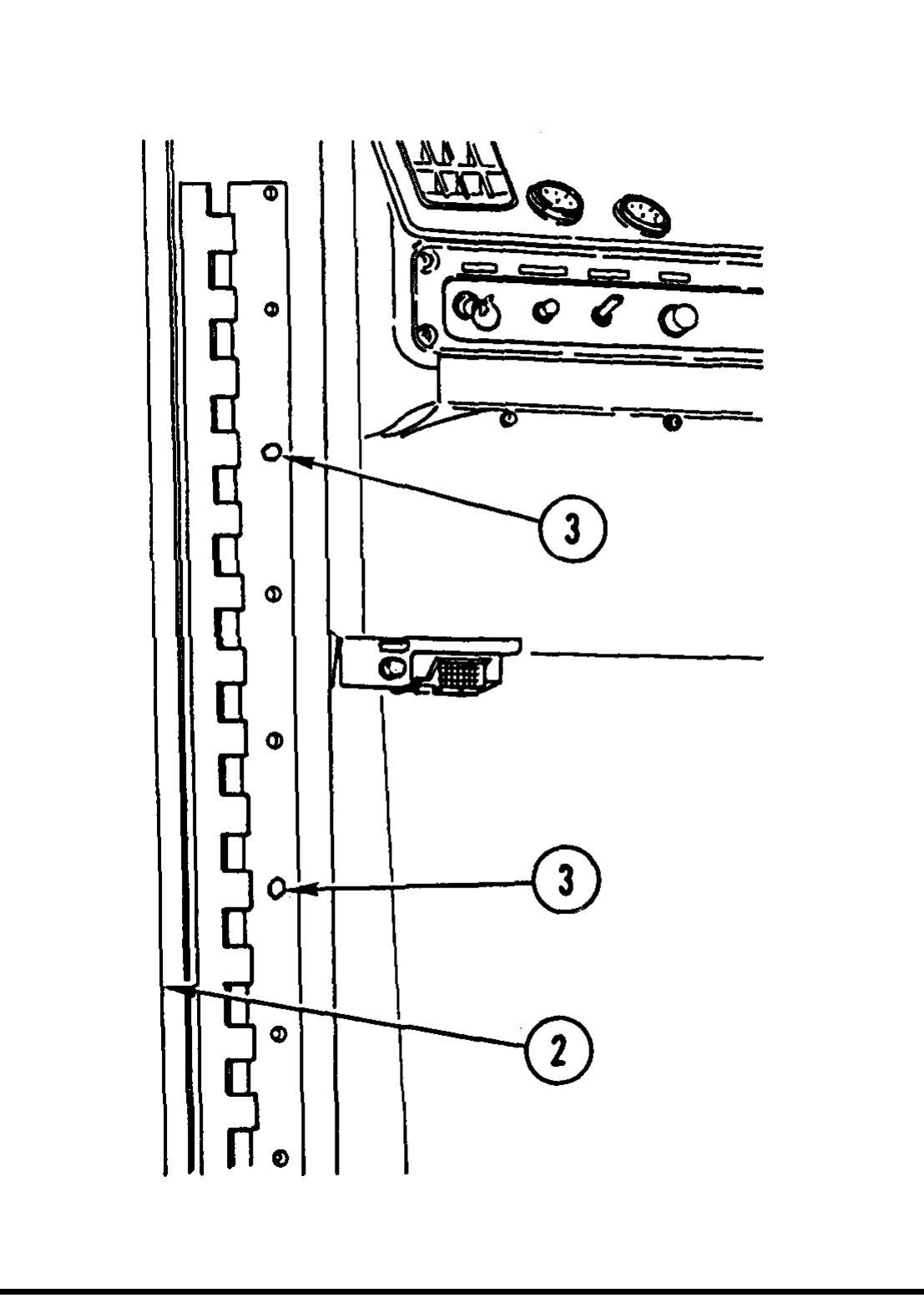
Due to size of door and angle for installation, use minimum of two personnel to install door. Failure to do so could result in injury to personnel.
2. INSTALL DOOR (2).
3. INSTALL TWO CAPSCREWS (3) HAND-TIGHT IN LOCATIONS INDICATED.
4. PERFORM DOOR ADJUSTMENT IN ACCORDANCE WITH TM 9-2320-363-20.
5. INSTALL REMAINING SIX CAPSCREWS (3).
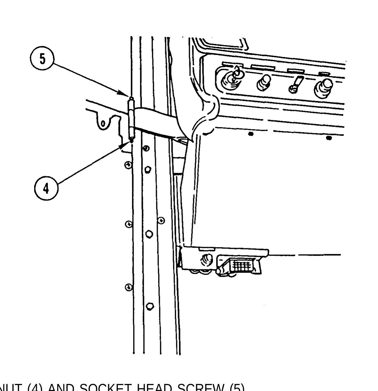
6. INSTALL CAP NUT (4) AND SOCKET HEAD SCREW (5).

This chapter illustrates and describes procedures for maintenance of the winch and related parts. A list of tasks contained in this chapter is shown below.
Page
Hydraulic Pump Replacement (M916A1 and M916A2) . . . . . . . . . . . . . . . . . . . . 11-2 Hydraulic Winch Replacement (M916A1 and M916A2) . . . . . . . . . . . . . . . . . 11-9 Hydraulic Motor Replacement (M916A1 and M916A2) . . . . . . . . . . . . . . . . . 11-15 Counterbalance Valve Replacement and Repair (M916A1 and M916A2) . . . . . . . 11-20 Speed Control Valve Replacement (M916A1 and M916A2) . . . . . . . . . . . . . . . . . . 11-26 Direction Control Valve Replacement (M916A1 and M916A2) ............... 11-30
Hydraulic Winch Frame Replacement (M916A1 and M916A2) . . . . . . . . . . . . . . . . 11-34
Winch Hydraulic Oil Filter Adapter Replacement (M916A1 and M916A2) . . . . . . . 11-39 Power Take-Off (PTO) Replacement (All Except M915A2) . . . . . . . . . . . . . . . . . . 11-42