Cab Replacement
TM 9-2320-363-34-1 · Chapter 10 — Body, Cab, Hood, and Hull Maintenance
This task covers:   a. Removal b. Cleaning c. Inspection d. Installation

Applicable Configuration:                            Equipment Condition (Cont):
M915A2                                               Reference               Condition Description
Tools and Special Equipment:                         TM 9-2320-363-20        Foot Brake Valve
                                                                             Removed
Tool Kit, SC 5180-90-CL-N05
Cab Sling, J39520                                    Page 10-84              Rear Window Removed
Materials/Parts:                                     Page 10-52              Windshield Removed
Nut, Kep                                             TM 9-2320-363-20        Radio Mounting Bracket
                                                                             Removed
Personnel Required: (3)                              TM 9-2320-363-20        Transmission Shift
                                                                             Control Removed
References:
                                                     TM 9-2320-363-20        Floor Mats Removed
TM 9-2320-363-20
                                                     TM 9-2320-363-20        Personnel Heater
Equipment Condition:                                                         Removed
Reference                   Condition Description    Page 10-36              Air Ducts Removed
Page 10-89                  Cab Doors Removed        TM 9-2320-363-20        Head Liners Removed
TM 9-2320-363-20            Muffler and Exhaust      TM 9-2320-363-20        Rotating Warning Light
                            Stack Removed                                    Bracket Removed
TM 9-2320-363-20            Exterior Grabhandles     TM 9-2320-363-20        Sunvisors Removed
                            Removed                  TM 9-2320-363-20        Air Horn and Valve
TM 9-2320-363-20            Fender Extensions                                Removed
                            Removed                  TM 9-2320-363-20        Interior Grabhandle
TM 9-2320-363-20            Hood Latches Removed                             Removed
TM 9-2320-363-20            Utility Lights Removed   TM 9-2320-363-20        Cab Liners Removed
TM 9-2320-363-20            Clearance Lights         TM 9-2320-363-20        Electronic Throttle
                            Removed                                          Removed
TM 9-2320-363-20            Windshield Wiper         TM 9-2320-363-20        Steering Column Support
                            Linkage Removed                                  Bracket Removed
TM 9-2320-363-20            Voltage Regulator        TM 9-2320-363-20        Brake Pedal Removed
                            Removed
                                                     Page 4-36               Overhead Cab Wiring
TM 9-2320-363-20            Dual Voltage Control                             Harness Removed
                            Removed
                                                     Page 4-6                Chassis Wiring Harness
TM 9-2320-363-20            Starter Regulator                                Removed
                            Removed
                                                     Page 4-20               STE/lCE Wiring Harness
                                                                             Removed
Equipment Condition (Cont):
Reference              Condition Description      General Safety InstructIons:
TM 9-2320-363-20       Air Tubes Removed
TM 9-2320-363-20       Anti-Lock Brake System                      WARNING
                       (ABS) Electronic Control          Cab assembly weighs 1,100 lb
                       Unit Removed                      (499 kg). Use hoist with lifting
TM 9-2320-363-20       Anti-Lock Brake System            capacity of 1,400 lb (636 kg) to
(ABS) Fuse and Relay support cab assembly. Failure Panel Removed to do so could result in injury Page 4-42 to personnel and/or damage to Cab Anti-Lock Brake cab assembly. System (ABS) Wiring Harness Removed
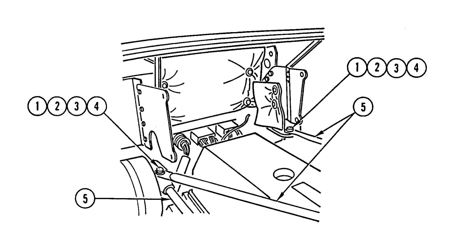
1. REMOVE TWO NUTS (1), TWO WASHERS (2), TWO BOLTS (3), AND TWO WASHERS (4) AND SWING THREE RADIATOR SUPPORT RODS (5) OUT OF THE WAY.
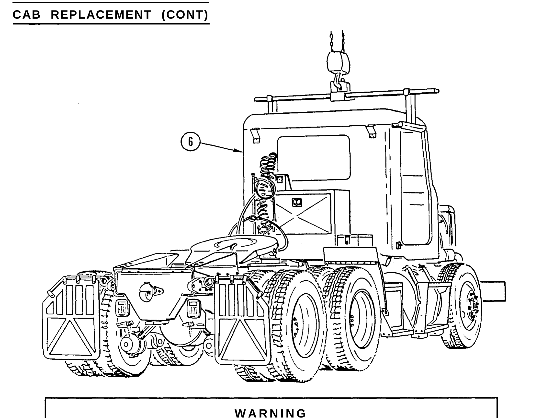
2. ATTACH CAB SLING AND HOIST TO CAB ASSEMBLY (6) AND REMOVE ALL SLACK FROM CHAIN.
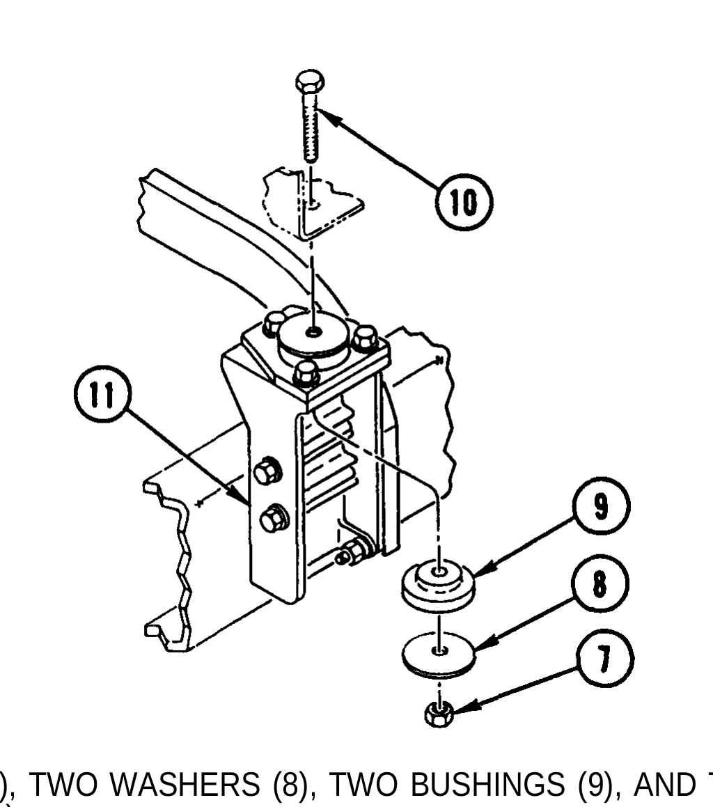
3. REMOVE TWO NUTS (7), TWO WASHERS (8), TWO BUSHINGS (9), AND TWO BOLTS (10) FROM FRONT CAB MOUNT (11).
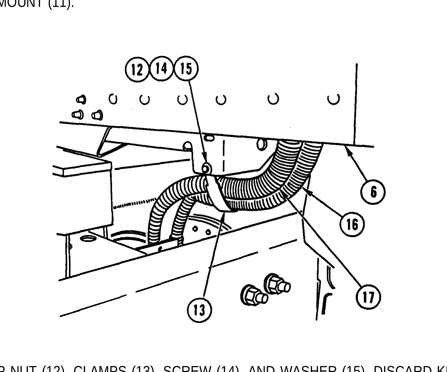
4. REMOVE KEP NUT (12), CLAMPS (13), SCREW (14), AND WASHER (15). DISCARD KEP NUT.
5. CAREFULLY PULL TWO WIRING HARNESSES (16 AND 17) FROM CAB ASSEMBLY (6).
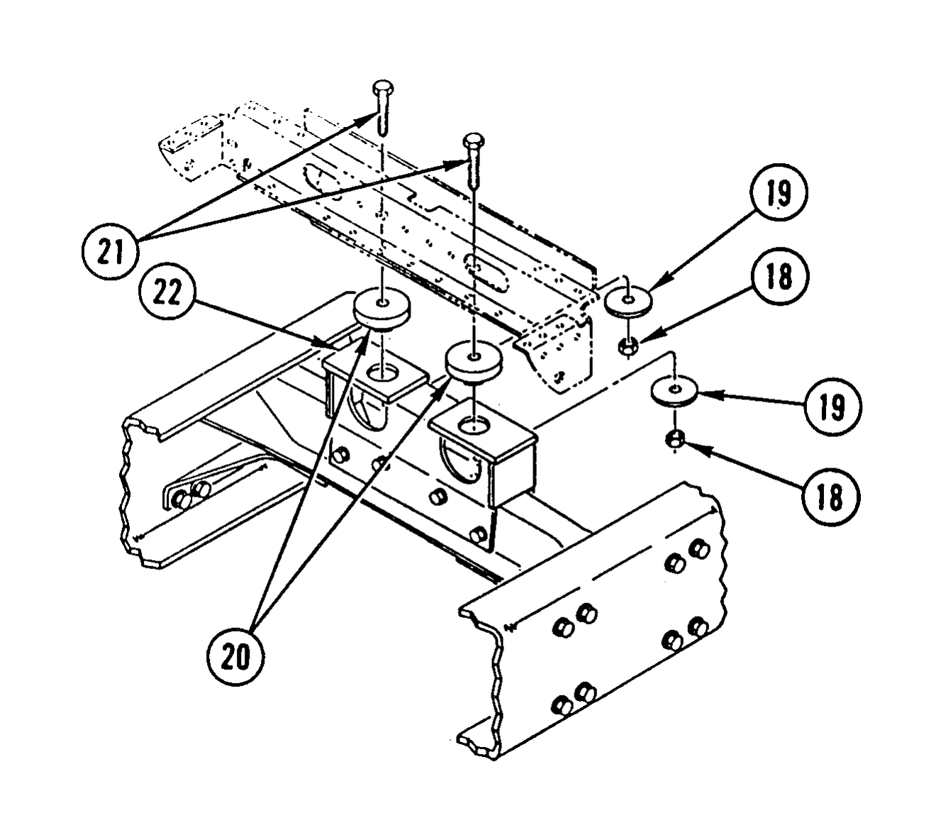
6. REMOVE TWO NUTS (18), TWO WASHERS (19), TWO BUSHINGS (20), AND TWO BOLTS (21) FROM REAR CAB MOUNT (22).
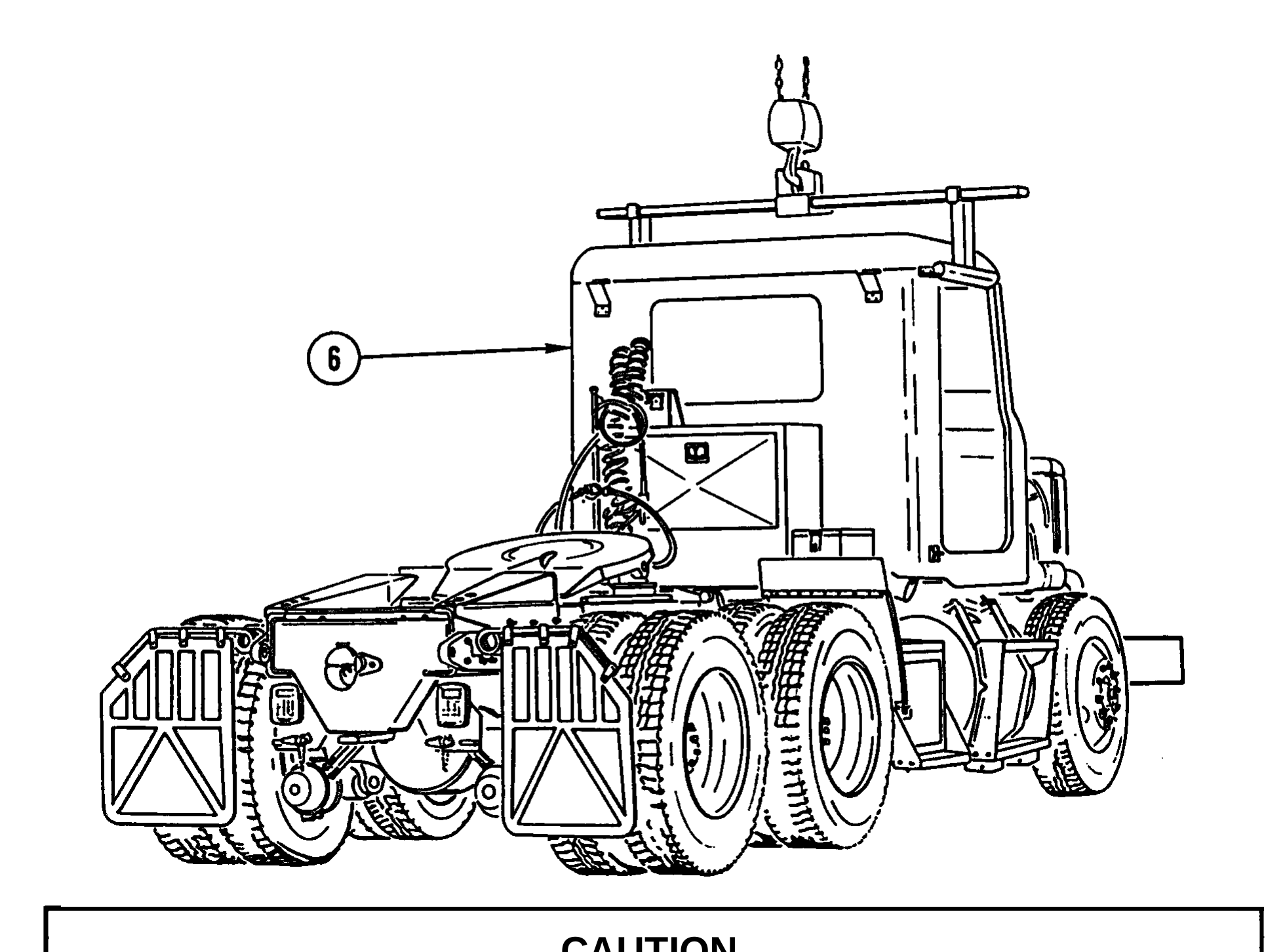
Lift cab slowly and check for parts that may still be connected to cab and vehicle structure. Failure to do so could result in damage to equipment.
7. REMOVE CAB ASSEMBLY (6).
Use general cleaning methods to clean all parts (page 2-30).
Inspect all parts for wear or damage.


1. ATTACH CAB SLING AND HOIST TO CAB ASSEMBLY (1) AND INSTALL CAB ASSEMBLY (1).
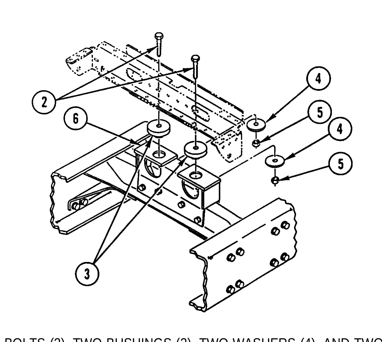
2. INSTALL TWO BOLTS (2), TWO BUSHINGS (3), TWO WASHERS (4), AND TWO NUTS (5) IN REAR CAB MOUNT (6).
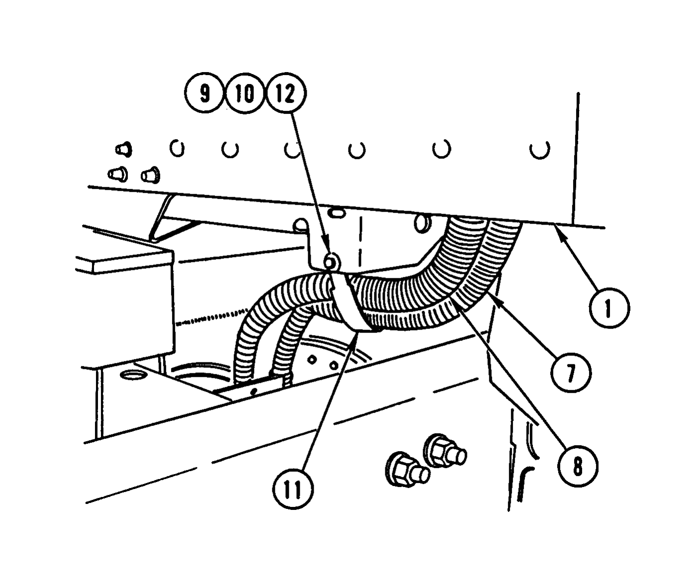
3. CAREFULLY INSTALL TWO WIRING HARNESSES (7 AND 8) IN CAB ASSEMBLY (1).
4. INSTALL WASHER (9), SCREW (10), CLAMP (11), AND NEW KEP NUT (12).
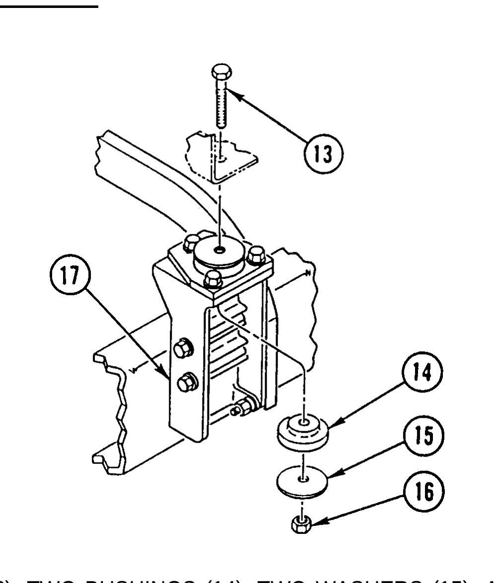
5. INSTALL TWO BOLTS (13), TWO BUSHINGS (14), TWO WASHERS (15), AND TWO NUTS (16) IN FRONT CAB MOUNT (17).
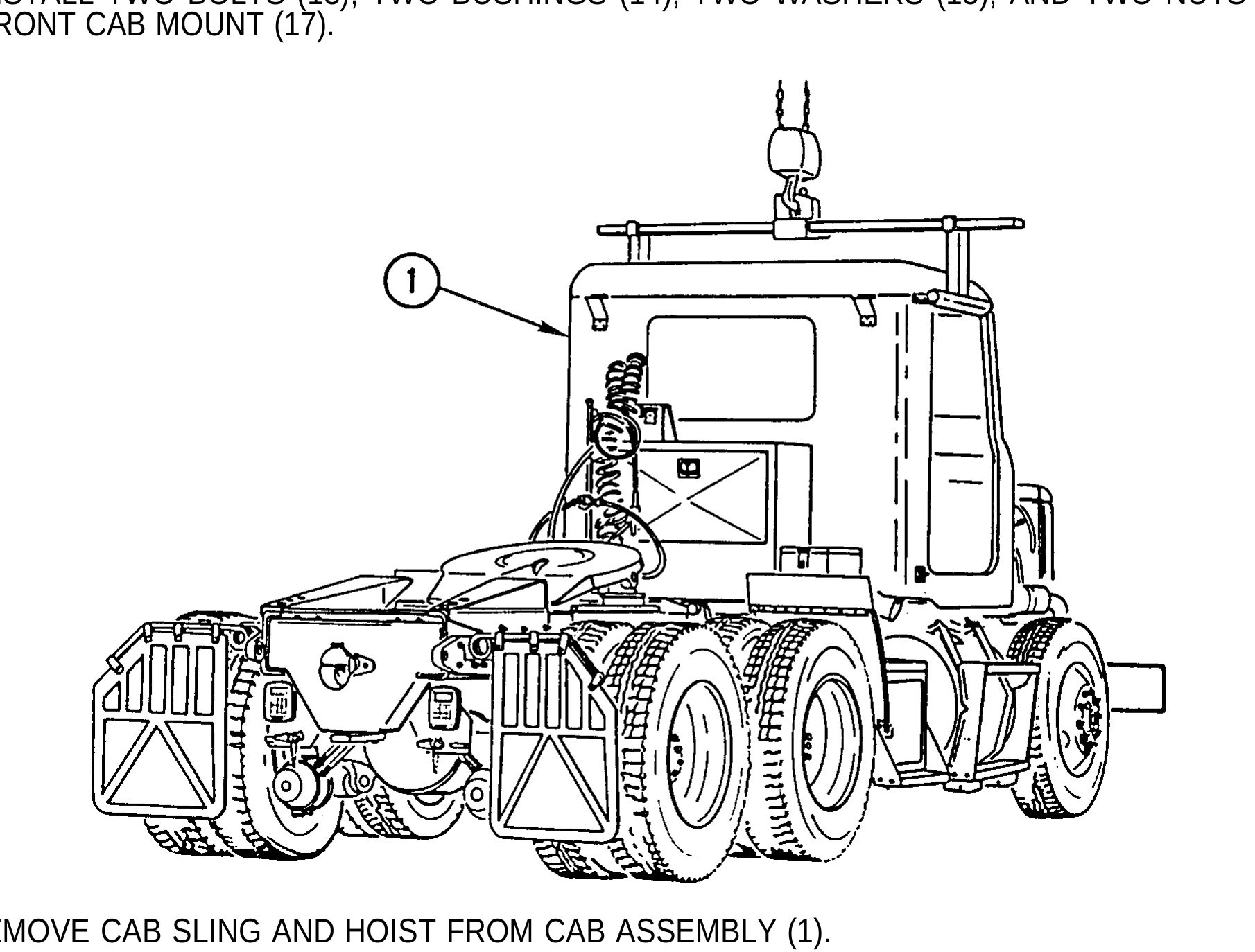
6. REMOVE CAB SLING AND HOIST FROM CAB ASSEMBLY (1).
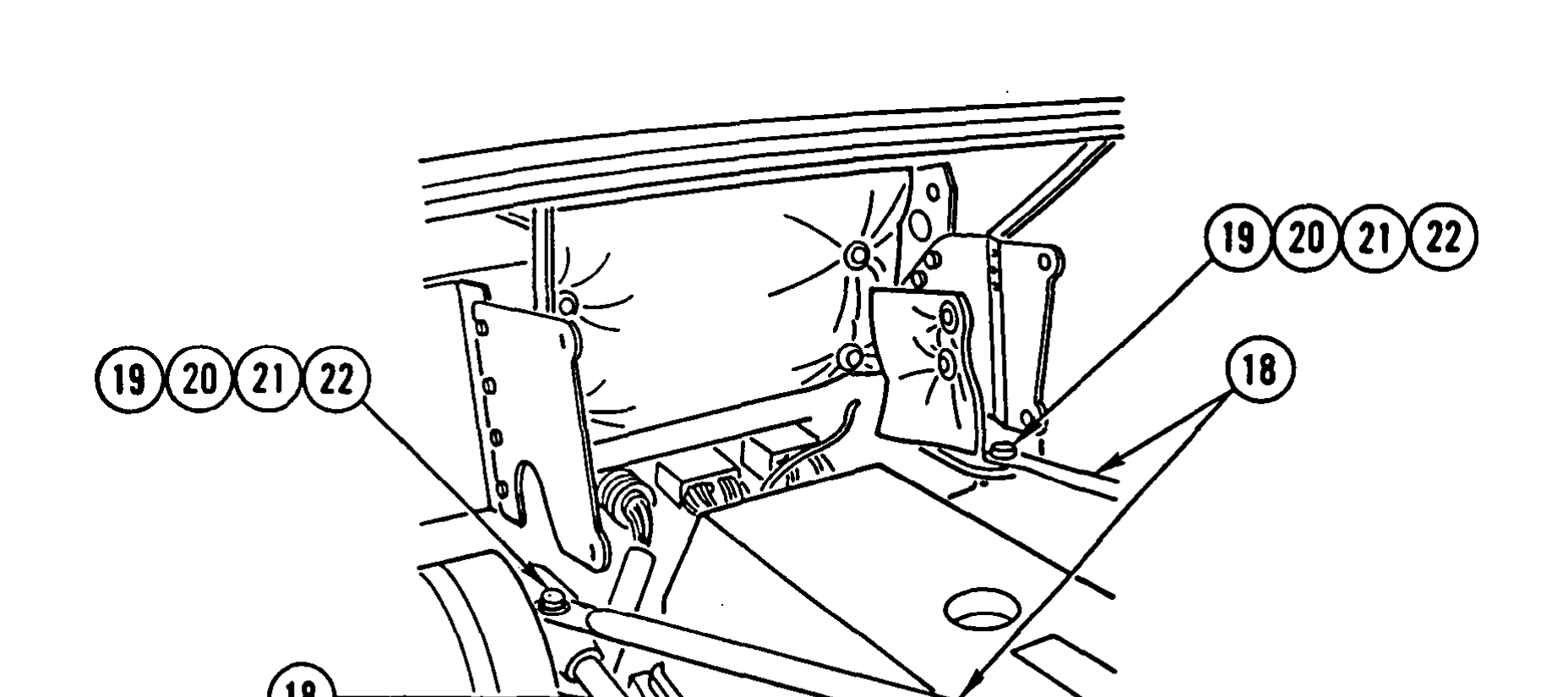
7. SWING THREE RADIATOR SUPPORT RODS (18) INTO PLACE AND INSTALL TWO WASHERS (19), TWO BOLTS (20), TWO WASHERS (21), AND TWO NUTS (22).
Install cab Anti-Lock Brake System (ABS) wiring harness (page 4-42). Install Anti-Lock Brake System (ABS) fuse and relay panel (TM 9-2320-363-20). Install Anti-Lock Brake System (ABS) electronic control unit (TM 9-2320-363-20). install air tubes (TM 9-2320-363-20). install STE/lCE wiring harness (page 4-20). Install chassis wiring harness (page 4-6). Install overhead cab wiring harness (page 4-36). Install brake pedal (TM 9-2320-363-20). Install steering column support bracket (TM 9-2320-363-20). Install electronic throttle (TM 9-2320-363-20). Install cab liners (TM 9-2320-363-20). Install interior grabhandle (TM 9-2320-363-20). Install air horn and valve (TM 9-2320-363-20). Install sunvisors (TM 9-2320-363-20). Install rotating warning light bracket (TM 9-2320-363-20). Install head liners (TM 9-2320-363-20). Install air ducts (page 10-36). Install personnel heater (TM 9-2320-363-20). Install floor mats (TM 9-2320-363-20). Install transmission shift control (TM 9-2320-363-20). Install radio mounting bracket (M915A2) (TM 9-2320-363-20). Install windshield (page 10-52). Install rear window (page 10-84). Install foot brake valve (TM 9-2320-363-20). Install starter regulator (TM 9-2320-363-20). Install dual voltage control (TM 9-2320-363-20). Install voltage regulator (TM 9-2320-363-20).
Install windshield wiper linkage (TM 9-2320-363-20). Install clearance lights (TM 9-2320-363-20). Install utility lights (TM 9-2320-363-20). Install hood latches (TM 9-2320-363-20). install fender extensions (TM 9-2320-363-20) Install exterior grabhandles (TM 9-2320-363-20). Install muffler and exhaust stack (TM 9-2320-363-20). Install cab doors (page 10-89).
This task covers:   a. Removal b. Cleaning c. Inspection d. Installation

Applicable Configuration:                            Equipment Condition (Cont):

All except M915A2                                    Reference               Condition Description

Tools and Special Equipment:                         Page 10-52              Windshield Removed

Tool Kit. SC 5180-90-CL-N05                          TM 9-2320-363-20        Transmission Shift
Cab Sling, J39520                                                            Control Removed

Personnel Required: (3)                              TM 9-2320-363-20        Transfer Case Shift
                                                                             Control Removed
References:                                          TM 9-2320-363-20        Floor Mats Removed
TM 9-2320-363-20                                     TM 9-2320-363-20        Personnel Heater
                                                                             Removed
Equipment Condition:
                                                     Page 10-36              Air Ducts Removed
Reference                 Condition Description
                                                     TM 9-2320-363-20        Head Liners Removed
Page 10-89                Cab Doors Removed
                                                     TM 9-2320-363-20        Rotating Warning Light
TM 9-2320-363-20          Muffler and Exhaust                                Bracket Removed
                          Stack Removed
                                                     TM 9-2320-363-20        Sunvisors Removed
TM 9-2320-363-20            Exterior Grabhandles
                            Removed                  TM 9-2320-363-20        Air Horn and Valve
                                                                             Removed
TM 9-2320-363-20            Fender Extensions
                            Removed                  TM 9-2320-363-20        Interior Grabhandle
                                                                             Removed
TM 9-2320-363-20            Hood Latches Removed
                                                     TM 9-2320-363-20        Cab Liners Removed
TM 9-2320-363-20            Utility Lights Removed
                                                     TM 9-2320-363-20        Electronic Throttle
TM 9-2320-363-20            Clearance Lights                                 Removed
                            Removed
                                                     TM 9-2320-363-20        Steering Column Support
TM 9-2320-363-20            Windshield Wiper                                 Bracket Removed
                            Linkage Removed
                                                     TM 9-2320-363-20        Brake Pedal Removed
TM 9-2320-363-20            Voltage Regulator
                            Removed                  Page 4-36               Overhead Cab Wiring
                                                                             Harness Removed
TM 9-2320-363-20            Dual Voltage Control
                            Removed                  Page 4-6                Chassis Wiring Harness
                                                                             Removed
TM 9-2320-363-20            Starter Regulator
                            Removed                  Page 4-20               STE/ICE Wiring Harness
                                                                             Removed
TM 9-2320-363-20            Foot Brake Valve
                            Removed                  TM 9-2320-363-20        Air Tubes Removed

Page 10-84                  Rear Window Removed
CAB REPLACEMENT (CONT)
General Safety Instructions:
1. REMOVE TWO NUTS (1), TWO WASHERS (2), TWO BOLTS (3), AND TWO WASHERS (4) AND SWING THREE RADIATOR SUPPORT RODS (5) OUT OF THE WAY.
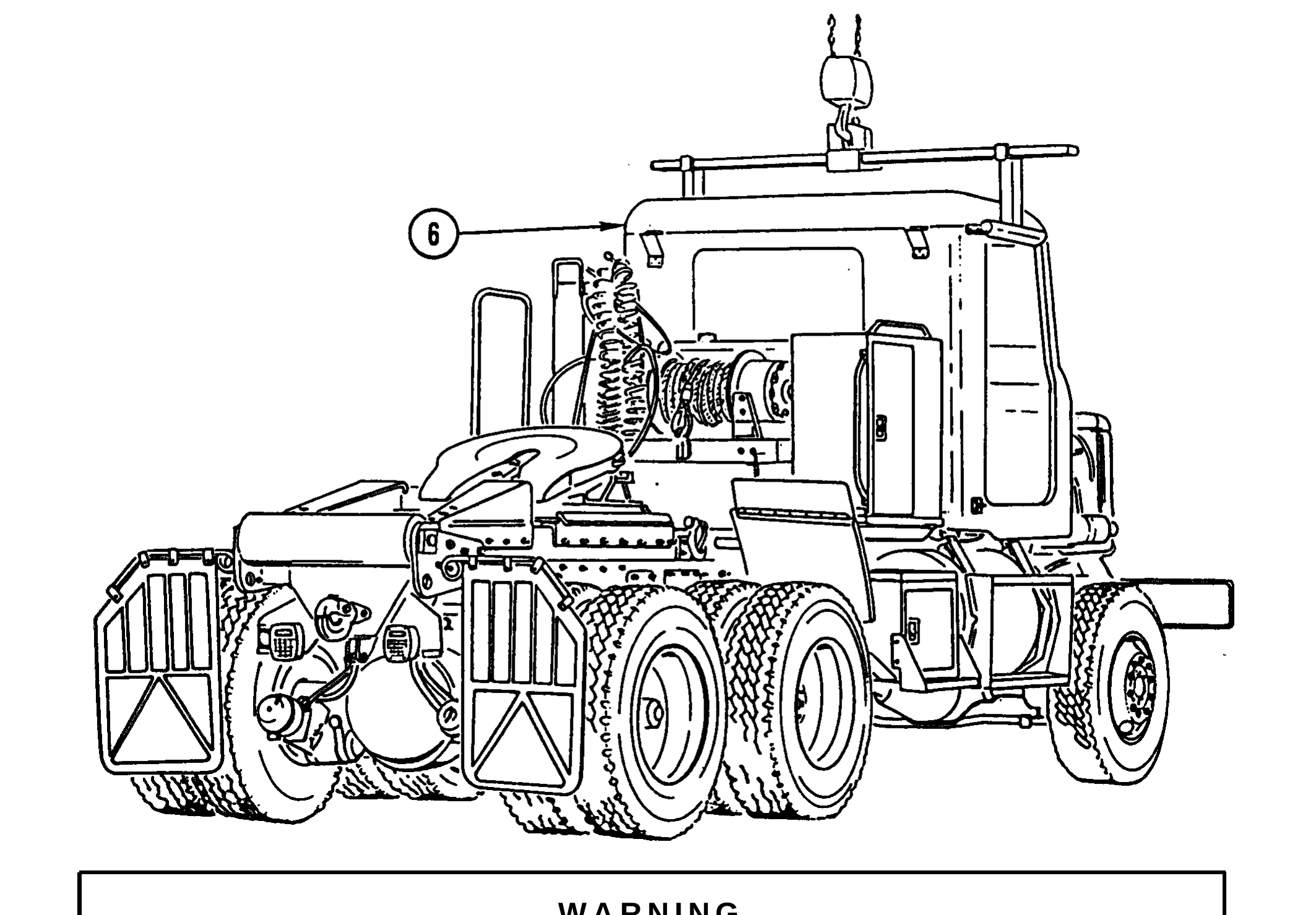
Cab assembly weighs 1,100 lb (499 kg). Use hoist with lifting capacity of 1,400 lb (636 kg) to support cab assembly. Failure to do so could result in injury to personnel and/or damage to cab assembly.
2. ATTACH CAB SLING AND HOIST TO CAB ASSEMBLY (6) AND REMOVE ALL SLACK FROM CHAIN.
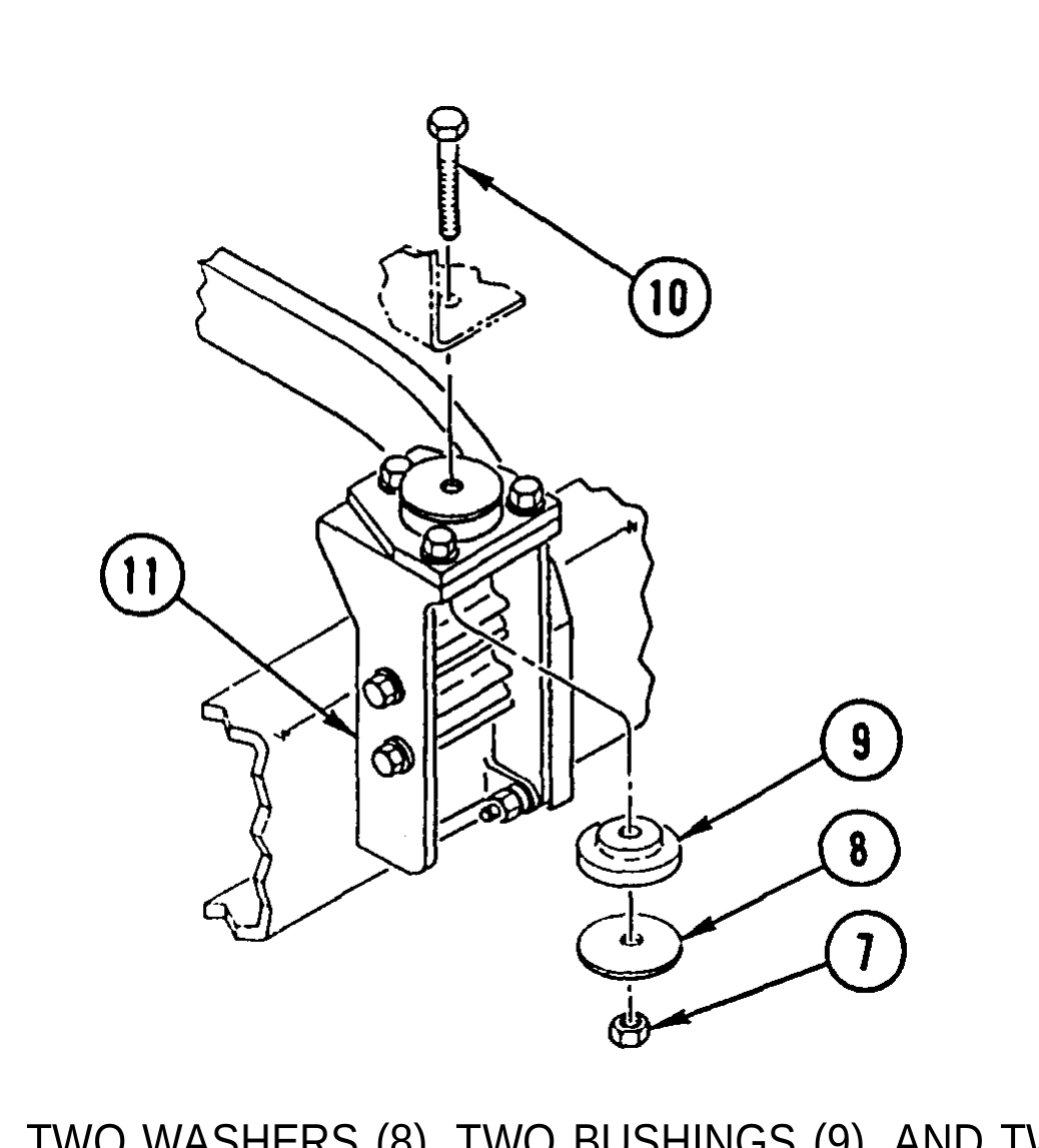
3. REMOVE TWO NUTS (7), TWO WASHERS (8), TWO BUSHINGS (9), AND TWO BOLTS (10) FROM FRONT CAB MOUNT (11).
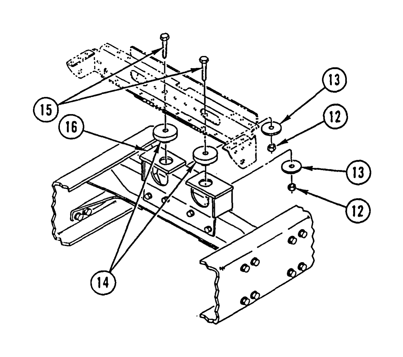
4. REMOVE TWO NUTS (12), TWO WASHERS (13), TWO BUSHINGS (14), AND TWO BOLTS (15) FROM REAR CAB MOUNT (16).
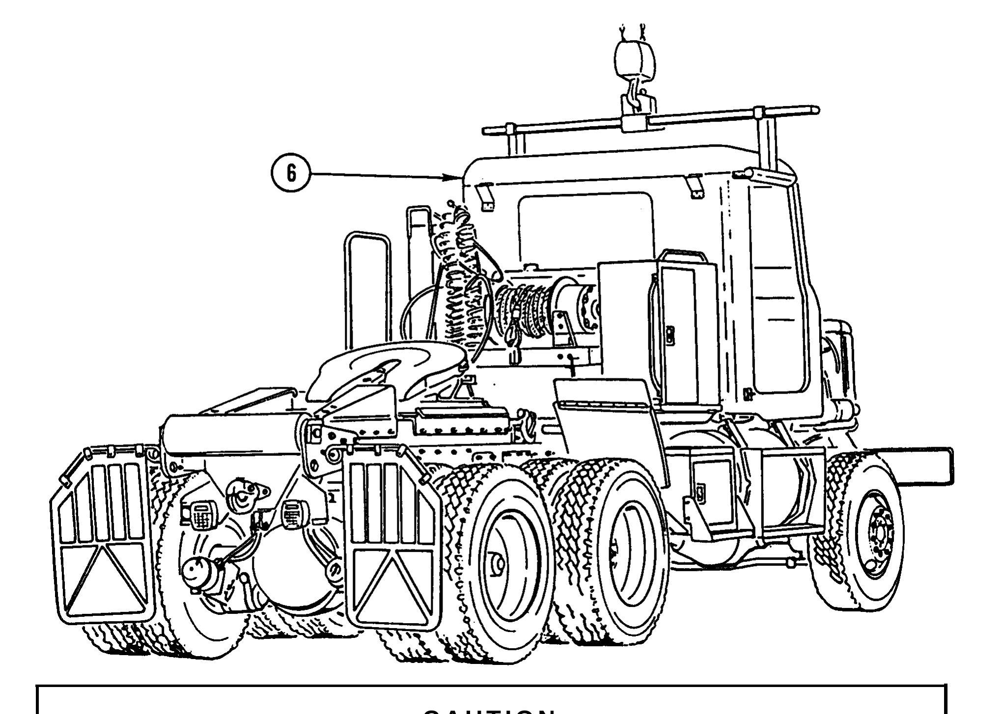
Lift cab slowly and check for parts that may still be connected to cab and vehicle structure. Failure to do so could result in damage to equipment.
5. REMOVE CAB ASSEMBLY (6).
Use general cleaning methods to clean all parts (page 2-30).
Inspect all parts for wear or damage.
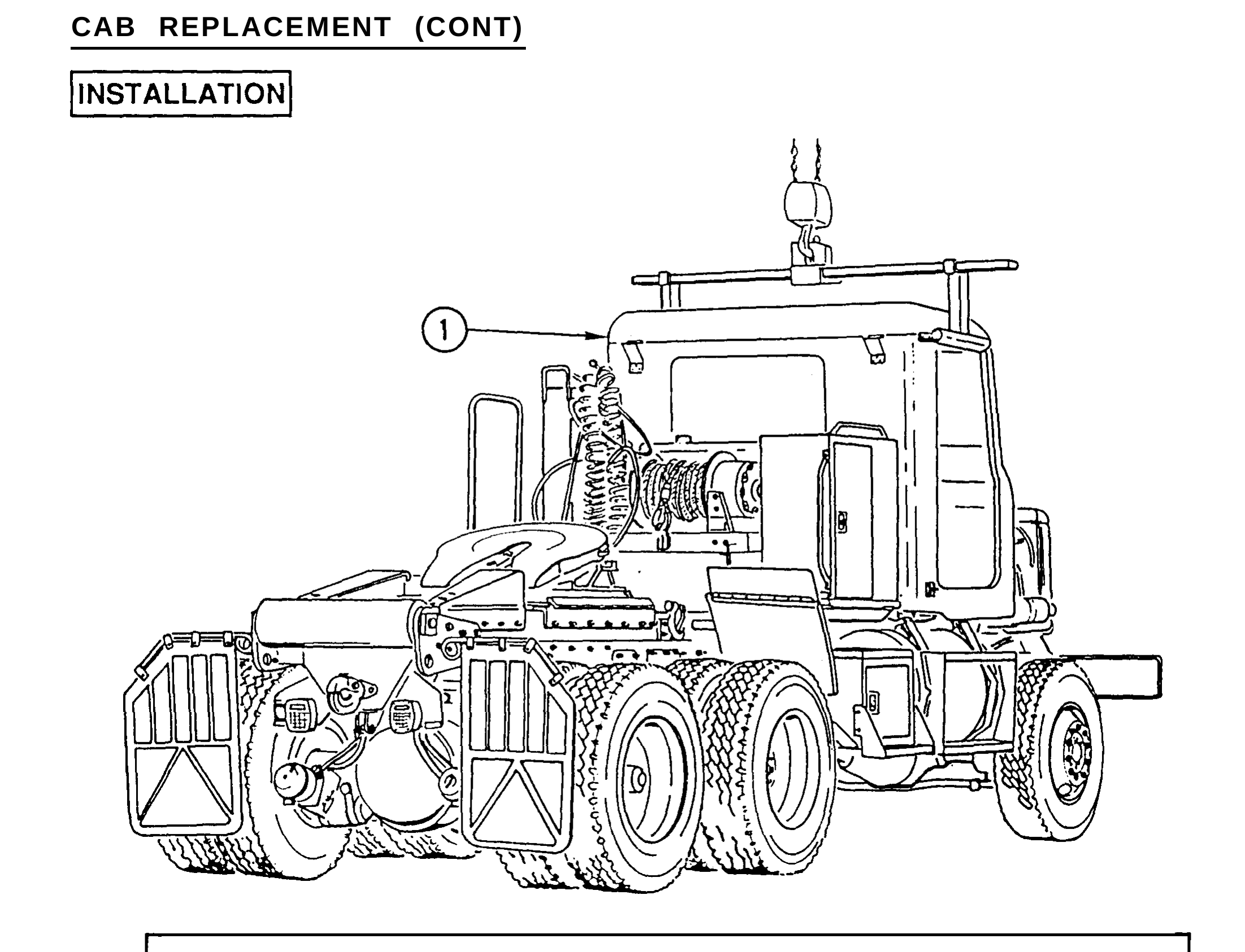
1. ATTACH CAB SLING AND HOIST TO CAB ASSEMBLY (1) AND INSTALL CAB ASSEMBLY (1).
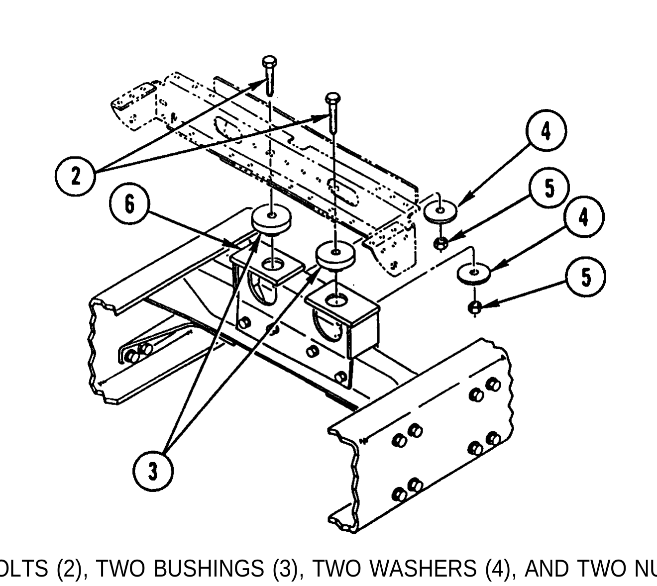
2. INSTALL TWO BOLTS (2), TWO BUSHINGS (3), TWO WASHERS (4), AND TWO NUTS (5) IN REAR CAB MOUNT (6).
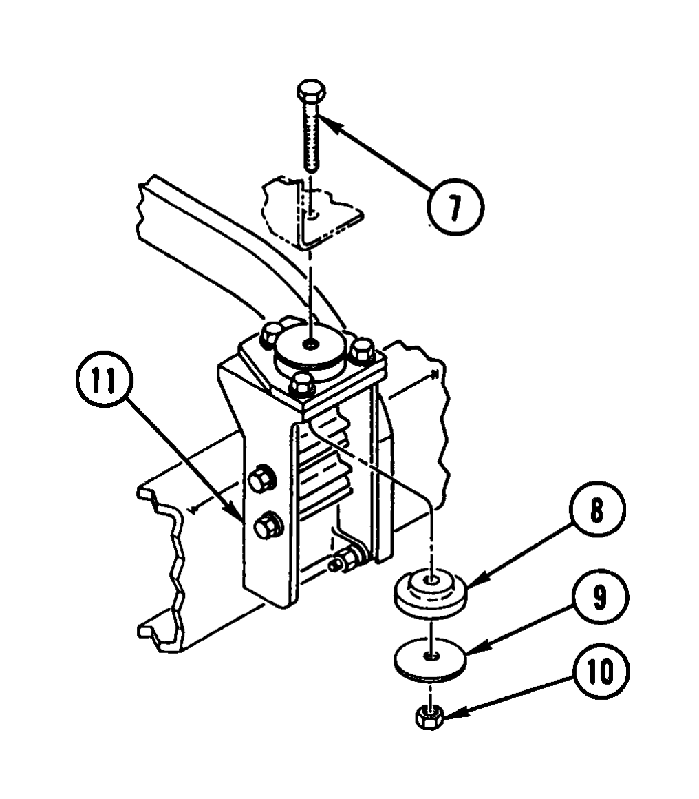
3. INSTALL TWO BOLTS (7), TWO BUSHINGS (6), TWO WASHERS (9), AND TWO NUTS (10) IN FRONT CAB MOUNT (11).
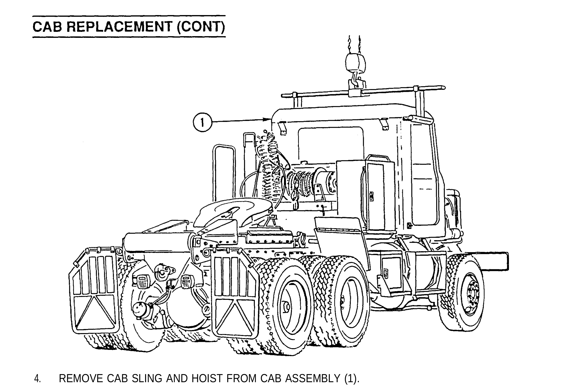
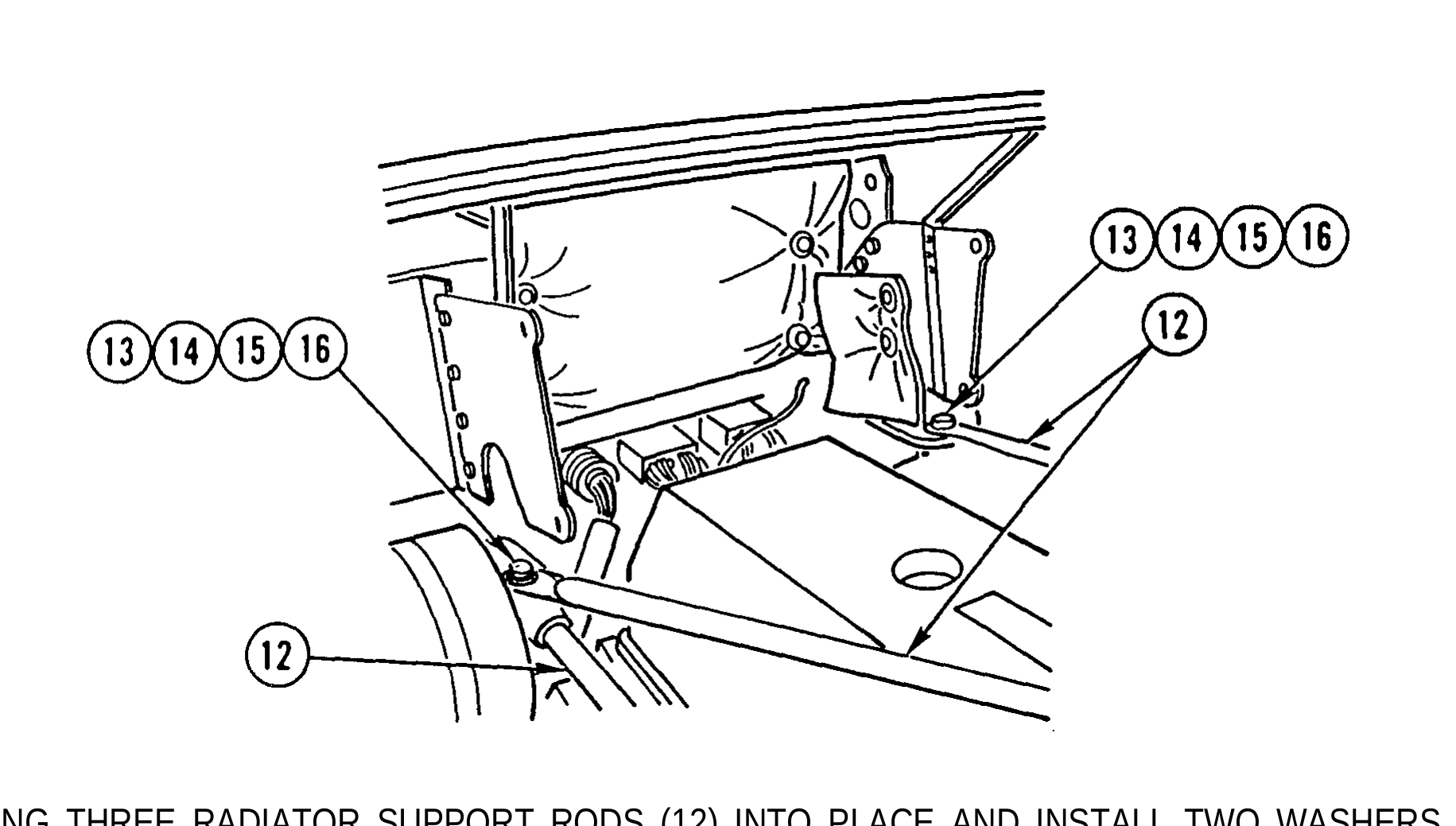
4. REMOVE CAB SLING AND HOIST FROM CAB ASSEMBLY (1).
5. SWING THREE RADIATOR SUPPORT RODS (12) INTO PLACE AND INSTALL TWO WASHERS (13), TWO BOLTS (14), TWO WASHERS (15), AND TWO NUTS (16).
Install air tubes (TM 9-2320-363-20), Inst all STE/lCE wiring harness (page 4-20). Inst all chassis wiring harness (page 4-6). Inst all overhead cab wiring harness (page 4-36). Inst all brake pedal (TM 9-2320-363-20). Inst all steering column support bracket (TM 9-2320-363-20). Inst all electronic throttle (TM 9-2320-363-20). Inst all cab liners (TM 9-2320-363-20). Inst all interior grabhandle (TM 9-2320-363-20). Inst all air horn and valve (TM 9-2320-363-20). Inst all sunvisors (TM 9-2320-363-20). Inst all rotating warning light bracket (TM 9-2320-363-20). Inst all head liners (TM 9-2320-363-20). Inst all air ducts (page 10-36). Inst all personnel heater (TM 9-2320-363-20). Inst all floor mats (TM 9-2320-363-20). Inst all transfer case shift control (TM 9-2320-363-20). Inst all transmission shift control (TM 9-2320-363-20). Inst all windshield (page 10-52). Inst all rear window (page 10-84). Inst all foot brake valve (TM 9-2320-363-20). Inst all starter regulator (TM 9-2320-363-20). Inst all dual voltage control (TM 9-2320-363-20). Inst all voltage regulator (TM 9-2320-363-20). Inst all windshield wiper linkage (TM 9-2320-363-20). Inst all clearance lights (TM 9-2320-363-20). Ins all utility lights (TM 9-2320-363-20). Inst all hood latches (TM 9-2320-363-20). Inst all fender extensions (TM 9-2320-363-20) Inst all exterior grabhandles (TM 9-2320-363-20). Inst all muffler and exhaust stack (TM 9-2320-363-20). Inst all cab doors (page 10-89).