2-40. Fan Drive Repair
TM 9-2815-237-34 · Chapter 2 — Engine Maintenance
This task covers:
a. Disassembly c. Inspection
b. Cleaning d. Assembly
INITIAL SETUP
  Tools                                            Personnel Required
      General mechanic’s tool kit:                     One mechanic
       automotive (Appendix E, Item 1)                 One assistant
  Materials/Parts                                  Equipment Condition
      Locknut (Appendix D, Item 24)                    Engine disassembled into subassemblies (para. 2-15).
      Spring (Appendix D, Item 50)
      Two shaft O-rings (Appendix D,               General Safety Instructions
      Items 32 or 33)                              ●   Use eyeshields when cleaning with compressed air.
      Friction lining (Appendix D, Item 23)        ●   Do not use compressed air to spin bearings.
      Cylinder O-ring (Appendix D, Item 30)
      Dust seal (Appendix D, Item 42)
      Lithium grease (Appendix B, Item 11)
  Manual References
      TM 9-2815-237-34P

a. Disassembly

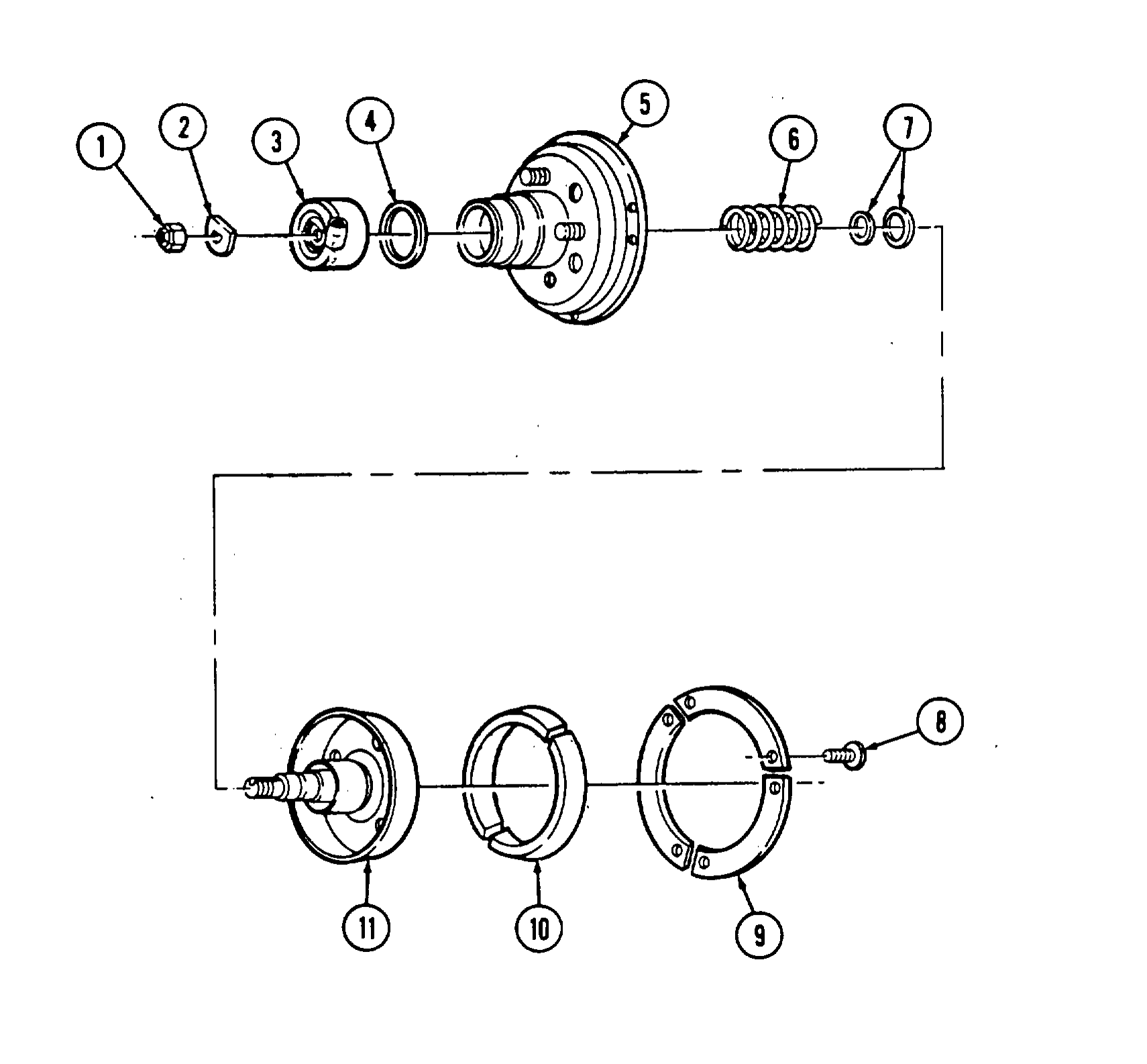
 1. Remove six screws (8) and three retaining plates (9) from housing (5).
 2. Remove friction lining (10) from housing (5). Discard friction lining (10).
 3. Remove locknut (1) and tabwasher (2) securing shaft assembly (11) and cylinder assembly (3)
     to housing (5). Discard locknut (1).
 4. Remove cylinder assembly (3) from front of housing (5).
 5. Remove O-ring (4) from inside cylinder assembly (3). Discard O-ring (4).
 6. Remove shaft assembly (11) and spring (6) from housing (5). Discard spring (6).
 7. Remove two O-rings (7) from shaft assembly (11). Discard O-rings (7)-
b. Cleaning
bearing with compressed air may cause injury to personnel or damage to equipment.
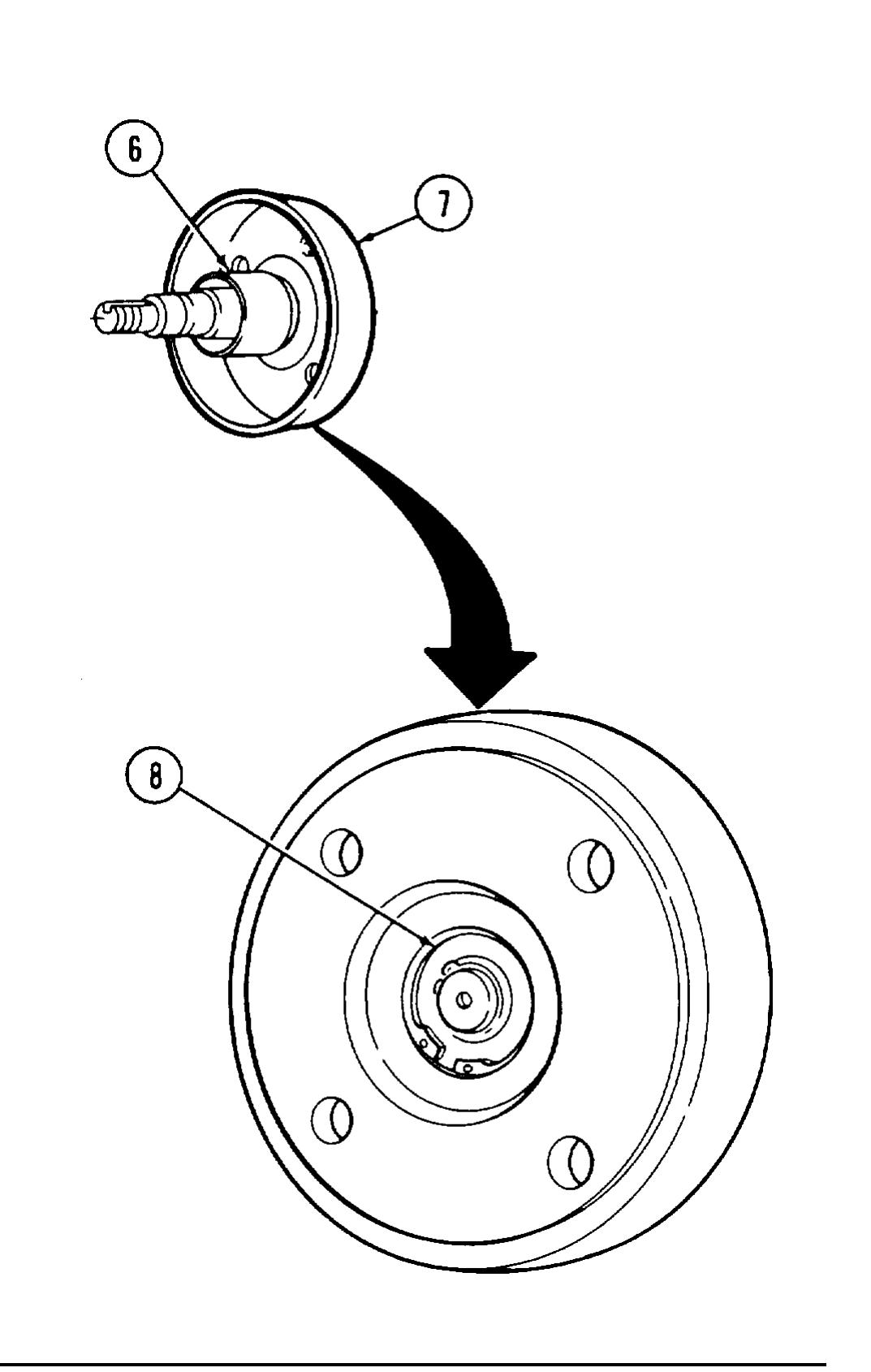
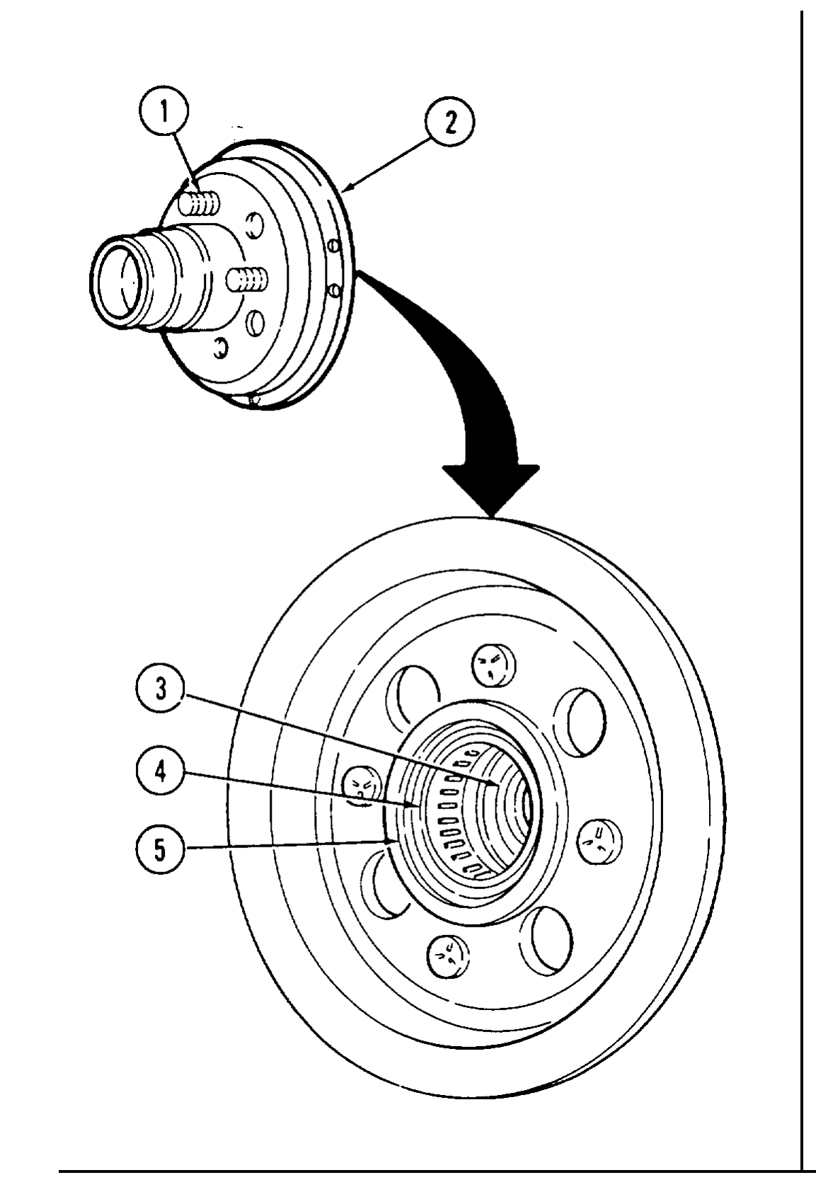
1. Clean shaft assembly (7) and housing (2) with compressed air and wipe with clean cloth.
2. Clean all other parts in accordance with para. 2-9.
c. Inspection
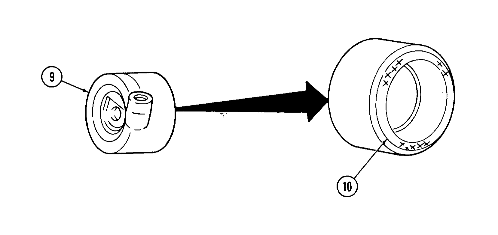
1. Inspect cylinder assembly (9) for damage. Replace if damaged.
2. Inspect dust seal (10) for cracks in the seal or pieces missing from it. Replace dust seal (10) if cracked or pieces missing from it. Ensure lip of seal is facing out.
3. Inspect roller bearings (3) and (4) in housing assembly (2) for damage. Replace fan drive assembly if damaged.
4. Inspect lip seal (5) in housing assembly (2) for damage. Replace fan drive assembly if damaged.
5. Inspect studs (1) on housing assembly (2) for stripped threads. Replace if damaged.
6. Inspect seal surface (6) on shaft assembly (7) for damage. Replace fan drive assembly if damaged.
7. Inspect bearing (8) on shaft assembly (7) for damage. Replace fan drive assembly if damaged.
d. Assembly
1. Install O-ring (4) in groove inside cylinder assembly (3).
2. Install cylinder assembly (3) on housing (5).
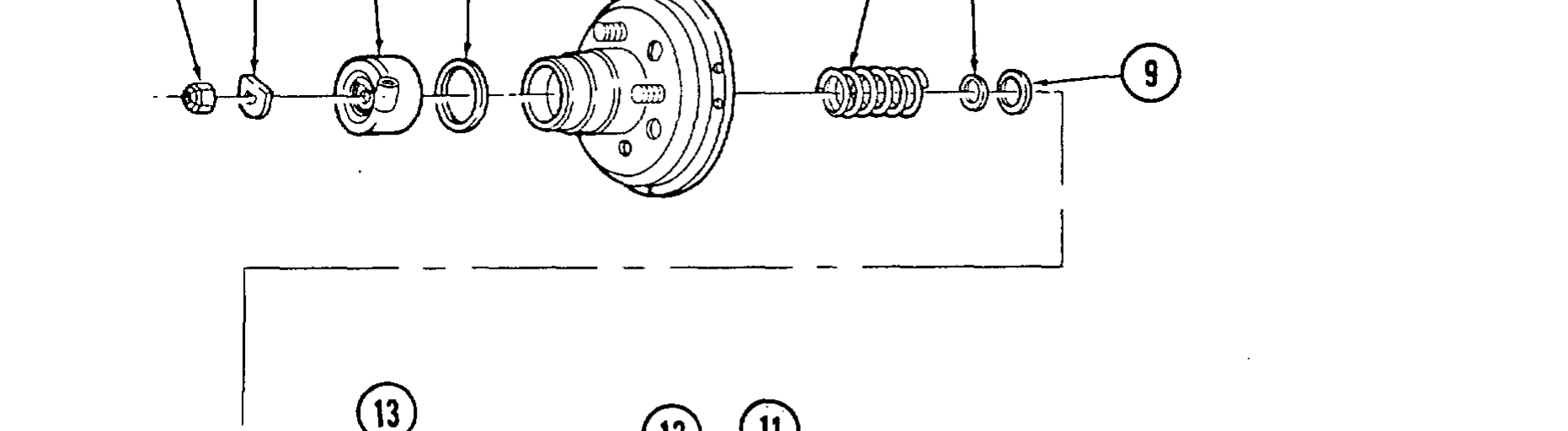
3. Install large O-ring (9) and small O-ring (8) on shaft assembly (13).
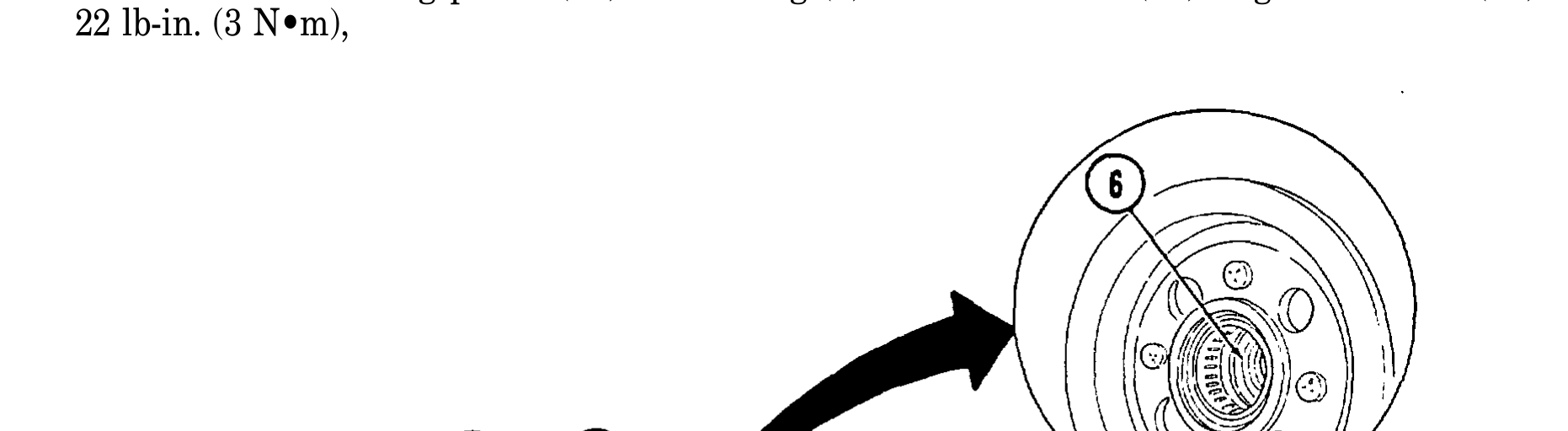
4. Lubricate roller bearing (6) with lithium grease,
5. Install shaft assembly (13) and spring (7) in housing (5).
6. Install shaft assembly (13) on cylinder assembly (3) with tabwasher (2) and locknut (1). Tighten locknut (1) to 96 lb-in. (11 N•m).
7. Install friction lining (12) in housing (5).
8. Install three retaining plates (11) on housing (5) with six screws (10). Tighten screws (10) to 22 lb-in. (3 N•m),