2-39. Water Crossover Repair
TM 9-2815-237-34 · Chapter 2 — Engine Maintenance
This task covers:
a. Disassembly c. Inspection
b. Cleaning d. Assembly
INITIAL SETUP:
  Tools                                                   Manual References
        General mechanic’s tool kit:                        TM 9-2815-237-34P
         automotive (Appendix E, Item 1)
                                                          Equipment Condition
  Materials/Parts                                           Engine disassembled into subassemblies
        Water crossover gasket (Appendix D, Item 19)        (para. 2-15).
        Pipe sealing compound (Appendix B, Item 17)

                                                   NOTE
                      In some cases, flanged head fasteners maybe present instead of
                      standard fasteners and washers. In all cases, washers should be
                      used when replacing a flanged head fastener with a standard
                      fastener.

a. Disassembly

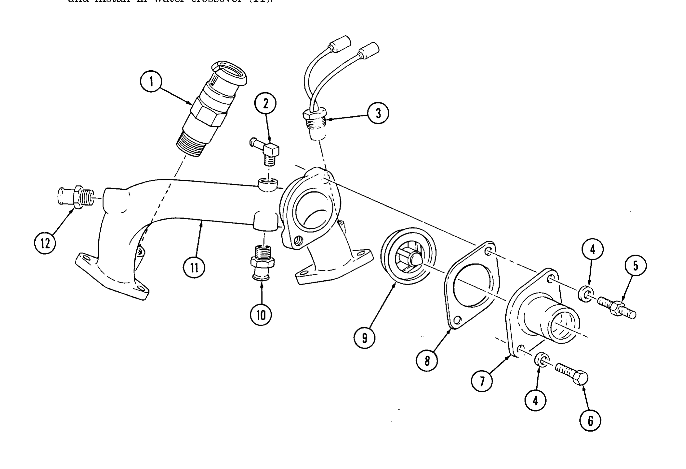
 1. Remove capscrew (6), stud (5), two washers (4), water outlet (7), thermostat (9), and gasket (8) from
     water crossover (11). Discard gasket (8).
                                                   NOTE
                      Only perform steps 2 through 4 if replacing water crossover or
                      damaged parts.
 2. Remove glow plug controller (1).
 3. Remove temperature switch (3).
 4. Remove de-airation nipple (2), bypass hose nipple (10), and heater hose nipple (12) from water
     crossover (11).
      b. Cleaning

 Clean all components in accordance with para. 2-9.
      c. Inspection

                                                     NOTE
                            For general inspection instructions, refer to para. 2-10.
 1. Inspect water crossover (11) and water outlet (7) for damage. Replace if damaged.
 2. Inspect all threaded holes in water crossover (11) for thread damage. Replace if threads are
      damaged.
 3. Inspect heater hose nipple (12), de-airation nipple (2), and bypass hose nipple (10) for damage.
      Replace if damaged.
 4. Inspect glow plug controller (1), thermostat (9), and temperature switch (3) for damage. Replace
      if damaged.
TM page 2-147
d. Assembly
CAUTION Thermostat must be installed correctly or engine damage may result. **NOTE**
For general assembly instructions, refer to para. 2-12.
1. Install thermostat (9), gasket (8), and water outlet (7) on water crossover (11) with two washers (4), capscrew (6), and stud (5). Tighten capscrew (6) and stud (5) t O 25 lb-ft (34 N•m).
2. Coat threads on heater hose nipple (12), bypass hose nipple (10), and de-airation nipple (2) with pipe sealing compound and install in water crossover (11).
3. Coat threads on glow plug controller (1) and temperature switch (3) with pipe sealing compound and install in water crossover (11).
TM page 2-148