2-41. Engine Assembly from Subassemblies
TM 9-2815-237-34 · Chapter 2 — Engine Maintenance
This task covers:
a. Crankshaft and Main Bearings q. Fuel Injection Nozzles
b. Flywheel r. Rocker Arm Shafts and Pushrods
c. Pistons and Connecting Rods s. Rocker Arm Covers
d. Oil Pump t. Modulator Link
e. Camshaft u. Fuel Supply and Return Lines
f. Timing Chain and Drive Sprockets v. Fuel Injection Lines
g. Timing Gear Cover w. Water Crossover
h. Oil Pan x. Intake Manifold
i. Oil Filter and Adapter y. Exhaust Manifold
j. Fuel Pump y.1. Turbocharger
k. Oil Pump Drive y.2. Manifold-to-Turbocharger Exhaust Pipe
l. Fuel Injection Pump y.3. Wastegate Housing
m. Water Pump and Adapter Plate y.4. Wastegate Actuator
n. Valve Lifters z. Torsional Damper
o. Cylinder Heads aa. Crankshaft Pulley
p. Glow Plugs bb. Fan Drive and Water Pump Pulley
INITIAL SETUP:
Tools                                            Materials/Parts (Cont’d)
   General mechanic’s tool kit:                    Water pump gasket (Appendix D, Item 22)
    automotive (Appendix E, Item 1)               Injection pump gasket (Appendix D, Item 15)
   Feeler gauge (Appendix E, Item 13)             Two cylinder head gaskets (Appendix D, Item 11)
   Piston ring compressor (Appendix E, Item 35)   Two water crossover gaskets (Appendix D, Item 20)
                                                  Eight injector nozzle gaskets (Appendix D, Item 16)
Special Tools                                      Two exhaust manifold gaskets (Appendix D, Item 12)
  Rear main seal installer                         Front cover oil seal (Appendix D, Item 43)
   (Appendix E, Items 33 or 34)                    Rear oil pan seal (Appendix D, Item 46)
  Injector nozzle socket (Appendix E, Item 5)      Oil filter (Appendix D, Item 6)
  Glow plug socket (Appendix E, Item 6)           Eight rod bearings (Appendix D, Item 1)
  Hex-head driver, 6 mm (Appendix E, Item 7)       Oil filter adapter bolt gasket (Appendix D, Item 7)
  Hex-head driver, 8 mm (Appendix E, Item 8)      Three    woodruff keys (Appendix D, Item 54)
  Hex-head driver, 5/16-in. (Appendix E, Item 9)  Oil pan gasket set (Appendix D, Item 9)
  Crowfoot, 16 mm (Appendix E, Item 36)            Two rocker arm cover gaskets
  Crowfoot, 19 mm (Appendix E, Item 37)             (Appendix D, Item 18)
                                                  Rear main oil seal (Appendix D, Items 44 or 45)
Personnel Required                                O-ring (Appendix D, Item 28)
   One mechanic                                   Adhesive (Appendix B, Item 1)
   One assistant                                  Bearing    clearance gauge (Appendix B, Item 9)
                                                  Sealer, anaerobic gasket (Appendix B, Item 10)
Manual References                                  Lubricating oil OE/HDO (Appendix B, Item 13)
  TM 9-2815-237-34P                                Silicone sealant (Appendix B, Item 16)
                                                  Pipe sealing compound (Appendix B, Item 17)
Materials/Parts                                    Sealing compound (Appendix B, Item 18)
  Turbocharger oil gasket (Appendix D, Item 19) General Safety Instructions
  Intake manifold gasket kit (Appendix D, Item 8)
                                                  • Crankshaft must be supported during
  Two center intake manifold gaskets,
                                                    removal and installation.
   turbocharged engine (Appendix D, Item 8.1)
                                                  • Do not perform this procedure near fire,
  Two O-rings (Appendix D, Item 31)                 flame, or sparks.
  Fuel pump gasket (Appendix D, Item 13)
  Adapter plate gasket (Appendix D, Item 10)
  Oil pump drive gasket (Appendix D, Item 17)
to make sure nothing has been overlooked during inspection and repair. Plugs should be checked for tightness, parts kept clean, openings covered, and machined surfaces protected. Application of lubricant should be performed from covered containers. ● Work area should be clean, well-ventilated, and free of blowing dirt
and dust. ● In some cases, flanged head fasteners may be present instead of
standard fasteners and washers. In all cases, washers should be used when replacing a flanged head fastener with a standard fastener. ● For general assembly instructions, refer to para. 2-12.
● Assembly procedures for pre-1990, 1990 and above 6.2L and 6.5L
engines are basically the same. Any differences in procedures are noted. Some replacement parts are different. Refer to para. 1-10 to determine engine model before ordering replacement parts.
a. Crankshaft and Main Bearings
determine what thickness main bearings to install. ● Main bearings are of the precision insert type and do not utilize shims for
adjustment. If clearances are found to be excessive, a new bearing, both upper and lower halves, will be required. Service bearings are available in standard size and undersize. ● Selective fitting of both rod and main bearing inserts is necessary in
production in order to obtain close tolerances. For this reason you may find one-half of a standard insert with one half of a 0.001 in. (0.025 mm) undersize insert, which will decrease the clearance 0.0005 in. (0.013 mm) from using a full standard bearing.
1. Remove all capscrews (1) and (2) and bearing caps (3) and install upper halves of main bearings (7) in cylinder block (6).
2. Install lower halves of main bearings (4) in bearing caps (3).
Crankshaft must be supported during removal and installation. Failure to support crankshaft may cause injury to personnel or damage to equipment.
3. Install crankshaft (8) in cylinder block (6).
4. Position gauging plastic on bearing journal (5) the full width of the bearing (4) and parallel to the center line of the crankshaft (8).
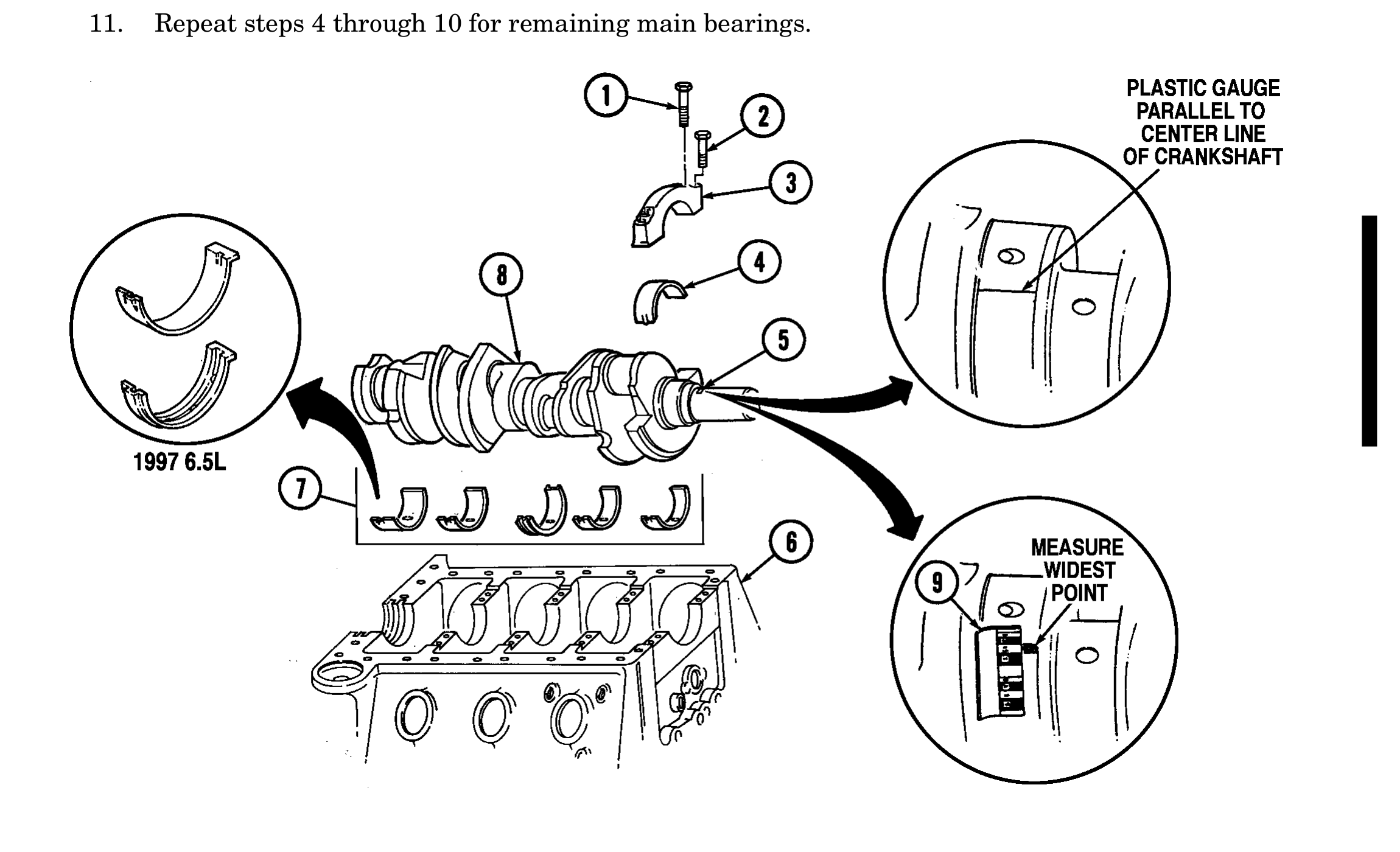
Bearing caps are numbered 1 through 5 and must be installed in correct order, starting with number 1 at front of cylinder block. Arrow on bearing cap must point forward or engine damage will result.
5. Install bearing cap (3) on cylinder block (6) with two long capscrews (1) and short capscrews (2). Tighten capscrews (1) and (2) finger tight.
6. Tighten all long capscrews (1) to 110 lb-ft (149 N•m). Tighten all short capscrews (2) to 100 lb-ft (136 N•m).
7. Remove two long capscrews (1), short capscrews (2), and bearing cap (3) from cylinder block (6).
8. On edge of envelope (9) there is a scale which is graduated in thousandths of an inch. Without removing gauging plastic, measure its thickness at the widest point with scale on envelope (9).
9. If gauging plastic tapers toward the middle or ends, there is a difference in clearance indicating taper, low spot, or irregularity of bearing or crankshaft journal. If gauging plastic indicates more than 0.001 in. (0.025 mm) taper, measure crankshaft journal with micrometer (para. 2-17).
10. If the measurement is within the specifications of 0.002-0.004 in. (0.051-0.102 mm), go to step 11. If measurement is not within specifications, a 0.0005 in. (0.013 mm) or 0.001 in. (0.025 mm) under- size bearing may produce proper bearing clearance. Replace bearings and repeat steps 4 through 10.
11. Repeat steps 4 through 10 for remaining main bearings.
Crankshaft must be supported during removal and installation. Failure to support crankshaft may cause injury to personnel or damage to equipment.
Bearing caps are numbered one through five and must be installed in correct order, starting with number one at front of cylinder block. Arrow on bearing cap must point forward or engine damage will result.
12. After all main bearing clearances have been set, remove crankshaft (7) and gauging plastic and apply OE/HDO to all main bearings. Install crankshaft (7), all bearing caps (1), (2), and (3), long cap- screws (4) and short capscrews (5). Tighten long capscrews (4) and short capscrews (5) to 12 lb-ft (16 N•m).
13. Tap crankshaft (7) rearward, then frontward; this will align main bearing thrust surfaces (6). Tighten long capscrews (4) and short capscrews (5) to 40 lb-ft (54 N•m).
14. Tighten all long capscrews (4) to 110 lb-ft (149 N•m). Tighten all short capscrews (5) to 100 lb-ft (136 N•m).
15. Rotate crankshaft (7) to ensure crankshaft (7) rotates freely.
16. Force the crankshaft (7) to the extreme front position and hold in place. Measure end play at the front end of the number three bearing with a feeler gauge. End play should be 0.004-0.010 in. (0.101-0.250 mm).
17. Remove long capscrews (4), short capscrews (5), bearing caps (1), (2), and (3), and crankshaft (7) from cylinder block (8).
18. Apply adhesive to seal groove in rear main bearing cap (1) and cylinder block (8).
19. Install rear main oil seal (9) into cylinder block (8) and rear main bearing cap (1) using seal installer.
20. Cut excess oil seal (9) off flush with bearing cap (1) and cylinder block (8) mounting surface.
21. Repeat steps 4 through 10 to ensure rear oil seal (9) did not affect rear main bearing clearance. If bearing clearance changed, remove bearing cap (1) and inspect rear oil seal (9).
22. Remove gauging plastic.
23. Install number three bearing cap (3), two long capscrews (4), and short capscrews (5). Tighten capscrews (4) and (5) to 12 lb-ft (16 N•m).
24. Tap crankshaft (7) rearward, then frontward; this will align main bearing thrust surfaces (6). Tighten capscrews (4) and (5) on number three bearing cap (3) to 40 lb-ft (54 N•m).
25. Apply thin film of sealer to rear main bearing cap (1) mating surface. Keep sealer off bearing and oil seal (9) (installed on 6.2L engines).
26. Install rear main bearing cap (1) on cylinder block (8) with long capscrews (4), and short cap- screws (5). Tighten capscrews (4) and (5) to 40 lb-ft (54 N•m).
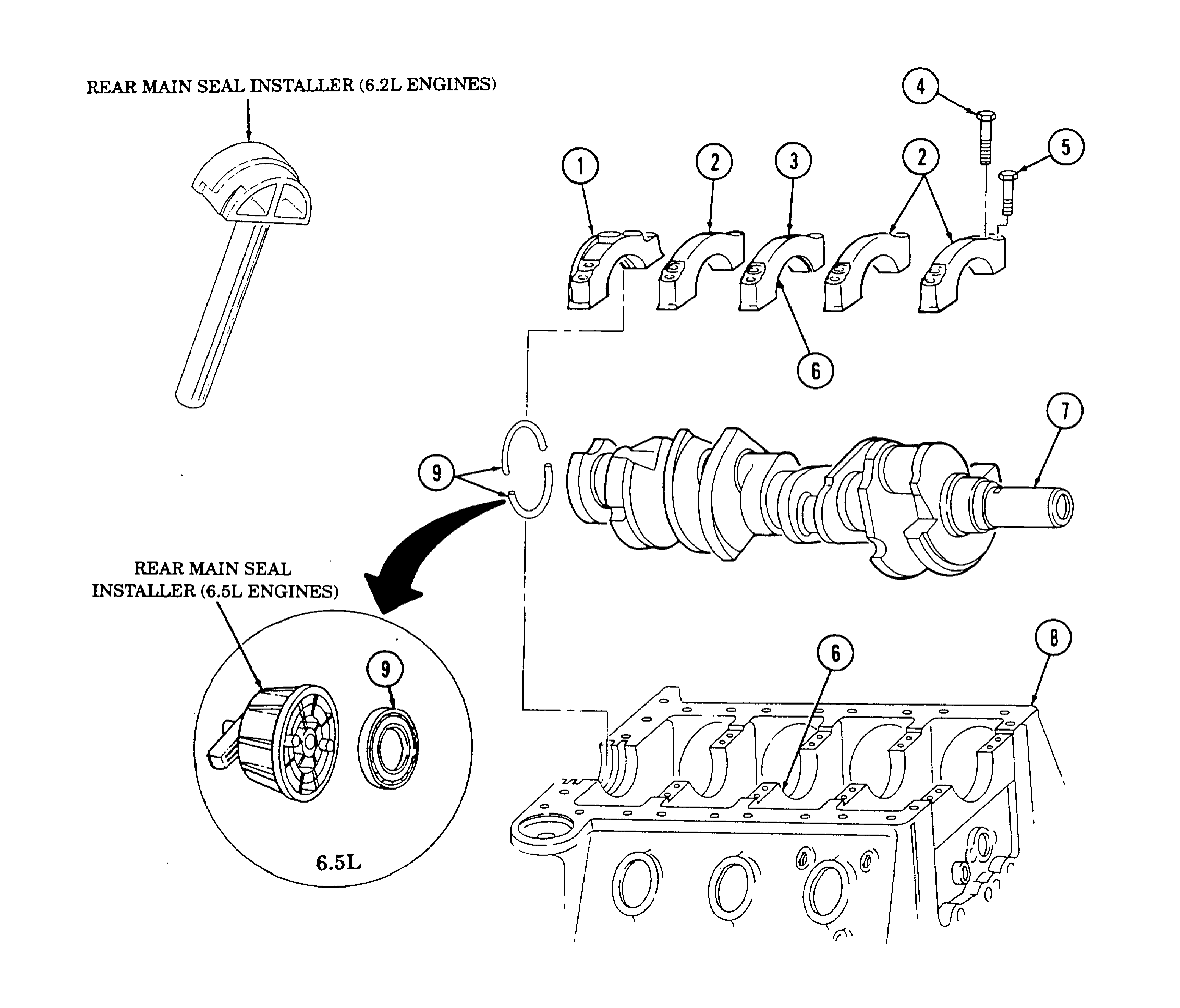
27. Install remaining bearing caps (2) on cylinder block (8) with long capscrews (4) and short capscrews (5). Tighten capscrews (4) and (5) to 40 lb-ft (54 N•m).
28. Evenly tighten all long capscrews (4) to 110 lb-ft (149 N•m).
29. Evenly tighten all short capscrews (5) to 100 lb-ft (136 N•m).
30. Coat rear crankshaft (7) surface with engine oil, and lightly coat lip of rear main oil seal (9) with engine oil.
31. Insttall rear main oil seal (9), with spring Cavity towards cylinder block (8), on crankshaft (7).
32. Using seal installer, drive rear main oil seal (9) in until tool bottoms against cylinder block (8) and
b. Flywheel
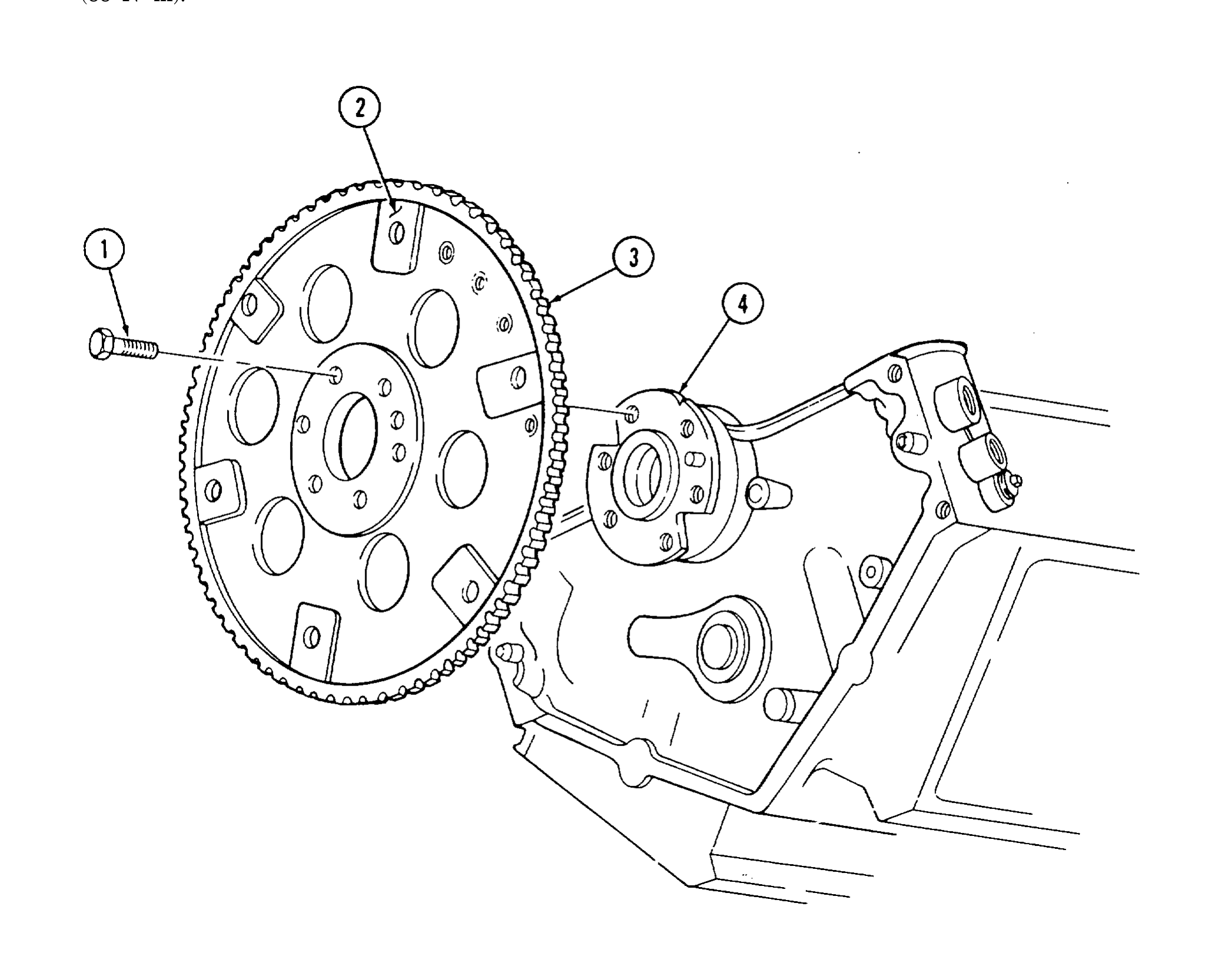
1. Install flywheel (3) on crankshaft (4) so that converter mounting surface (2) faces outward.
2. Secure flywheel (3) to crankshaft (4) with six capscrews (1). Tighten capscrews (1) to 65 lb-ft (88 N•m).
c. Pistons and Connecting Rods
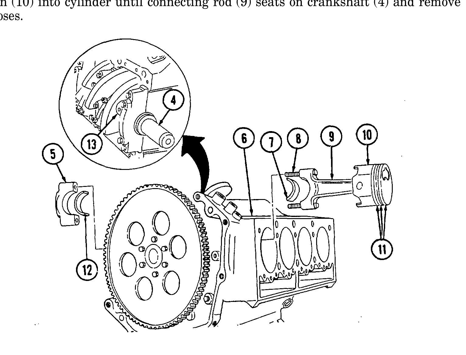
1. Rotate cylinder block (6) approximately 90°.
2. Check identification number on side of connecting rod (9) and install upper rod bearing half (7) in connecting rod (9) and lower rod bearing half (12) in corresponding rod cap (5).
3. Rotate crankshaft (4) so rod journal (13) faces outward.
4. Cover connecting rod bolts (8) with 3/8-in. inside diameter rubber hose.
5. Apply OE/HDO to piston rings (11) and piston (10).
6. Compress piston rings (11) with ring compressor.
of engine. ● Starting from front of cylinder block, cylinders 1, 3, 5, and 7 are
on left side and cylinders 2, 4, 6, and 8 are on right side. ● For remaining pistons, rotate crankshaft so rod journal faces outward.
7. Check identification number on side of connecting rod (9) and install piston (10) and connecting rod (9) into corresponding cylinder.
8. Tap piston (10) into cylinder until connecting rod (9) seats on crankshaft (4) and remove rubber hoses.
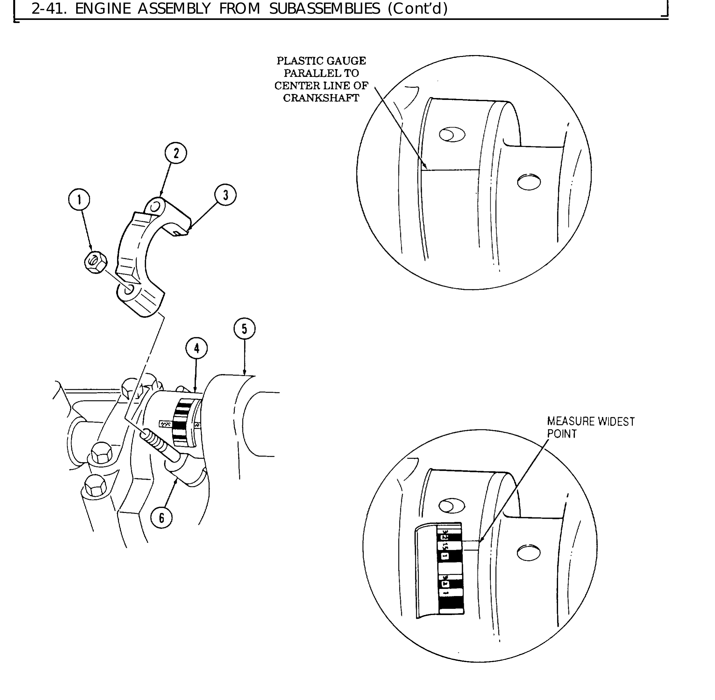
9. Position gauging plastic on bearing journal (3) the fill width of the bearing (4) and parallel to the center line of the crankshaft.
10. Check identification number on side of connecting rod (6) and install corresponding rod cap (2).
11. Secure rod cap (2) to connecting rod (6) with two nuts (1) and tighten to 44-52 lb-ft (60-71 N•m).
12. Remove two nuts (1) and rod cap (2) from connecting rod (6).
13. Measure gauging plastic at its widest point.
14. If the gauging plastic tapers toward the middle or ends, there is a difference in clearance indicating taper, low spot, or irregularity of bearing or crankshaft journal. If gauging plastic indicates more than 0.001 in. (0.025 mm) taper, measure crankshaft journal with micrometer (para. 2-17).
15. If the measurement is within specification, 0.002-0.004 in. (0.051-0.102 mm) bearing is satisfactory. If measurement is not within specifications, a 0.001 in. (0.025 mm) undersize bearing may produce proper bearing clearance. Replace bearings and repeat steps 9 through 15.
16. Remove gauging plastic.
17. Apply OE/HDO to rod bearings. Check identification number on side of connecting rod (6) and install corresponding rod cap (2).
18. Secure rod cap (2) to connecting rod (6) with two nuts (1) and tighten to 44-52 lb-ft (60-71 N•m).
19. Rotate crankshaft (5) to ensure crankshaft (5) rotates.
20. Repeat steps 2 through 19 for remaining pistons and connecting rods.
d. Oil Pump
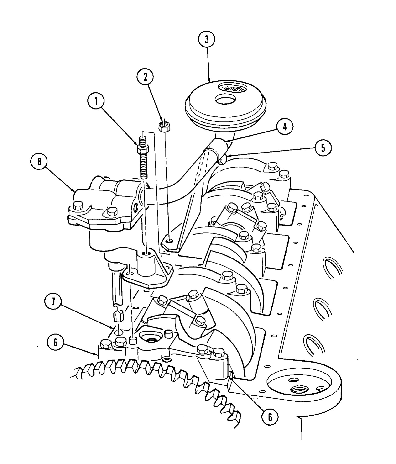
1. Rotate cylinder block (7) so crankshaft faces upward.
2. Install oil pump (8) on rear main bearing cap (6).
3. Install stud (1) and oil pump (8) on rear main bearing cap (6) and tighten stud (1) to 59-74 lb-ft (80-100 N•m).
4. Install pickup tube bracket (4) on stud (1) with nut (2). Tighten nut (2) to 35 lb-ft (48 N•m).
5. Tighten capscrew (5) securing pickup tube bracket (4) to pickup tube (3) to 12 lb-ft (16 N•m).
e. Camshaft
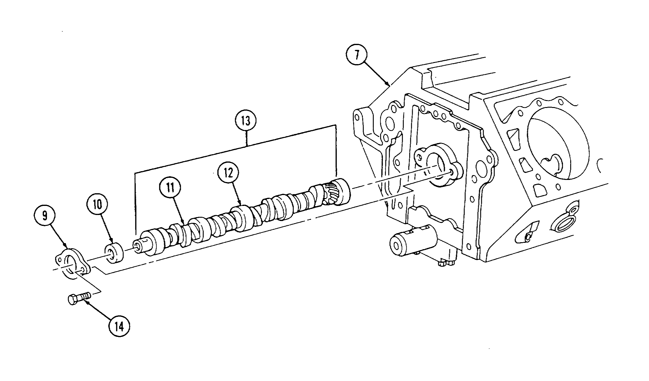
1. Rotate cylinder block (7) 180°.
2. Apply OE/HDO to all bearing journals (12) and cam lobes (11) on camshaft (13).
3. Install camshaft (13) into cylinder block (7).
4. Install spacer (10) and camshaft thrust plate (9) with two capscrews (14). Tighten capscrews (14) to 18 lb-ft (24 N•m).
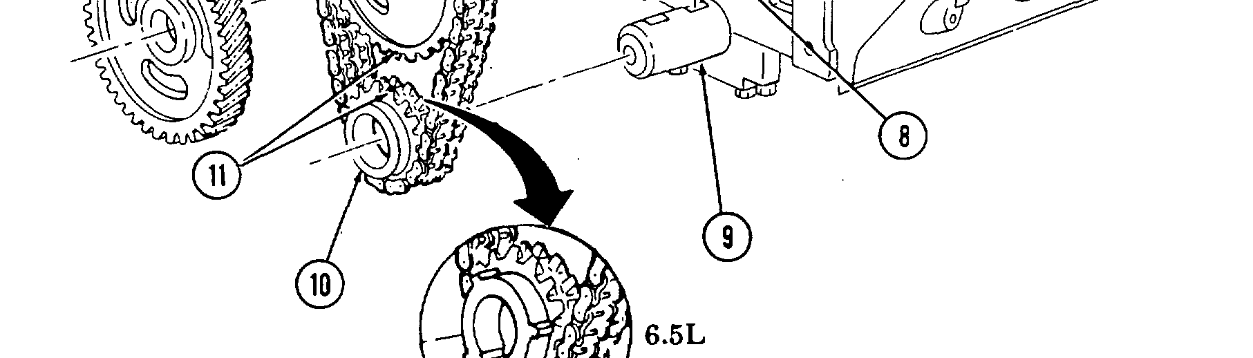
f. Timing Chain and Drive Sprockets
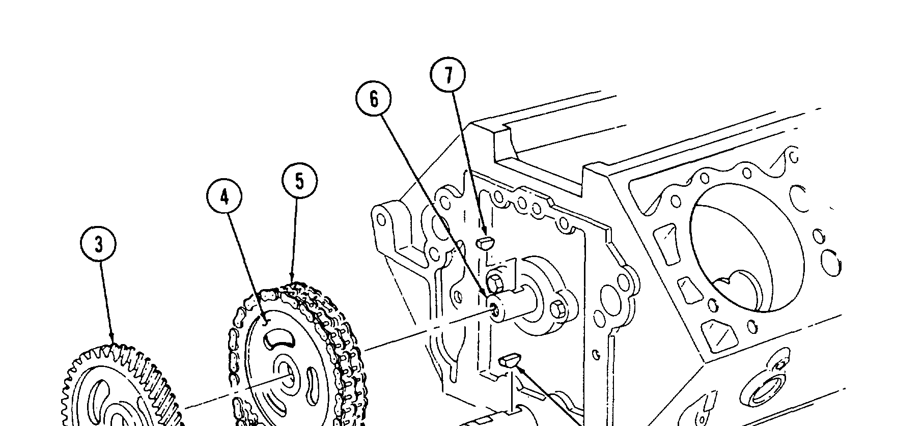
1, Install woodruff key (7) in camshaft (6) and woodruff key (8) in crankshaft (9).
2. Install crankshaft sprocket (10) and camshaft sprocket (4) in timing chain (5) and align timing marks (11). 3< Rotate crankshaft (9) and camshaft (6) so woodruff keys (7) and (8) align with keyway slots in crankshaft sprocket (10) and camshaft sprocket (4).
4. Install crankshaft sprocket (10), camshaft sprocket (4), and timing chain (5) as an assembly onto camshaft (6) and crankshaft (9).
5. Install pump drive gear (3) on camshaft (6) with washer (2) and capscrew (1). Tighten capscrew (1) to 55-66 lb-ft (75-90 N•m).
6. Apply OE/HDO to timing chain (5).
7. Check timing chain deflection midway between camshaft sprocket (4) and crankshaft sprocket (10). Total deflection must not exceed 0.5 in. (12.7 mm). If deflection exceeds specification, inspect cam- shaft sprocket (4) and crankshaft sprocket (10) for damage. Replace either if damaged and recheck deflection.
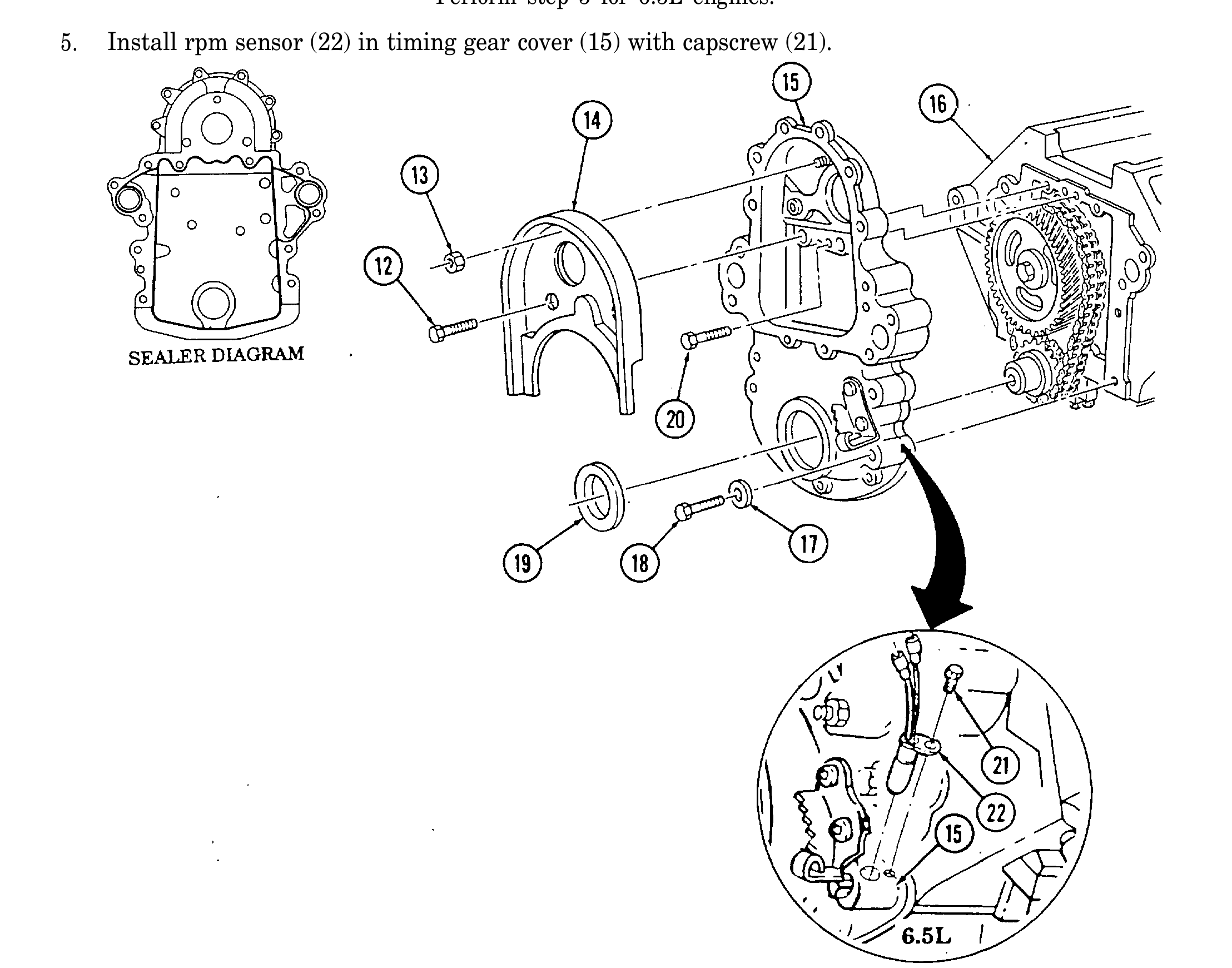
g. Timing Gear Cover
1. Install front cover seal (19) in timing gear cover (15), ensuring lip of seal (19) faces inward.
2. Apply a 3/32 in. (2 mm) bead of sealer to sealing surface on timing gear cover (15), following diagram shown.
3. Install timing gear cover (15) on cylinder block (16) with four washers (17), capscrews (18), and short capscrews (20). Tighten four capscrews (18) and short capscrews (20) to 33 lb-ft (45 N•m).
4. Install baffle plate (14) in timing gear cover (15) with two capscrews (12) and nut (13). Tighten capscrews (12) and nut (13) to 33 lb-ft (45 N•m).
5. Install rpm sensor (22) in timing gear cover (15) with capscrew (21).
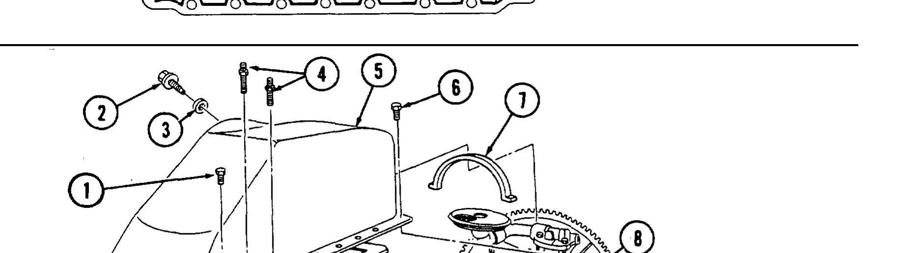
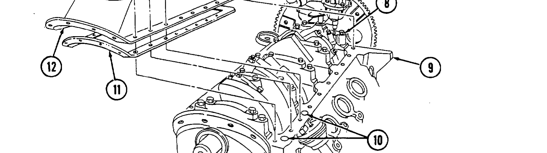
h. Oil Pan
1. Rotate cylinder block (9) 180°.
2. Install oil pan rear seal (7) in rear main cap (8) and apply a drop of silicone sealant at each end of seal (7).
● If applying silicone sealant, perform step 4. ● If installing new engine oil pan gasket, perform step 3. ● Silicone sealant can be applied with the gasket, but is not required.
3. Install engine oil pan gasket (11) on oil pan sealing surface (12) and align with capscrew holes.
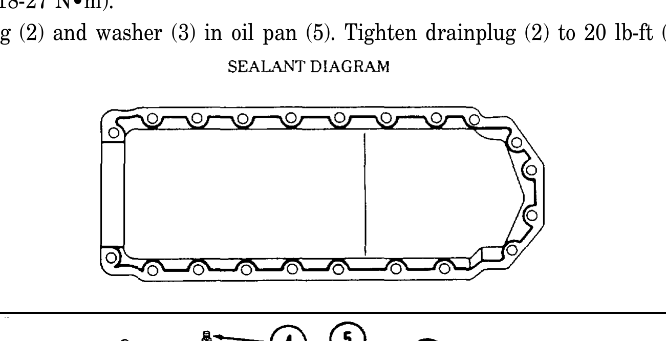
4. Apply a 3/16 in. (5 mm) bead of silicone sealant around two large holes (10) on cylinder block (9). Apply a 3/16 in. (5 mm) bead of silicone sealant around oil pan sealing surface (12), following diagram shown.
5. Install oil pan (5) on cylinder block (9) with twenty capscrews (1), two studs (4), and two large capscrews (6). Tighten studs (4) and capscrews (1) to 48-120 lb-in. (5-14 N•m) and capscrews (6) to 156-240 lb-in. (18-27 N•m).
6. Install drainplug (2) and washer (3) in oil pan (5). Tighten drainplug (2) to 20 lb-ft (27 N•m).
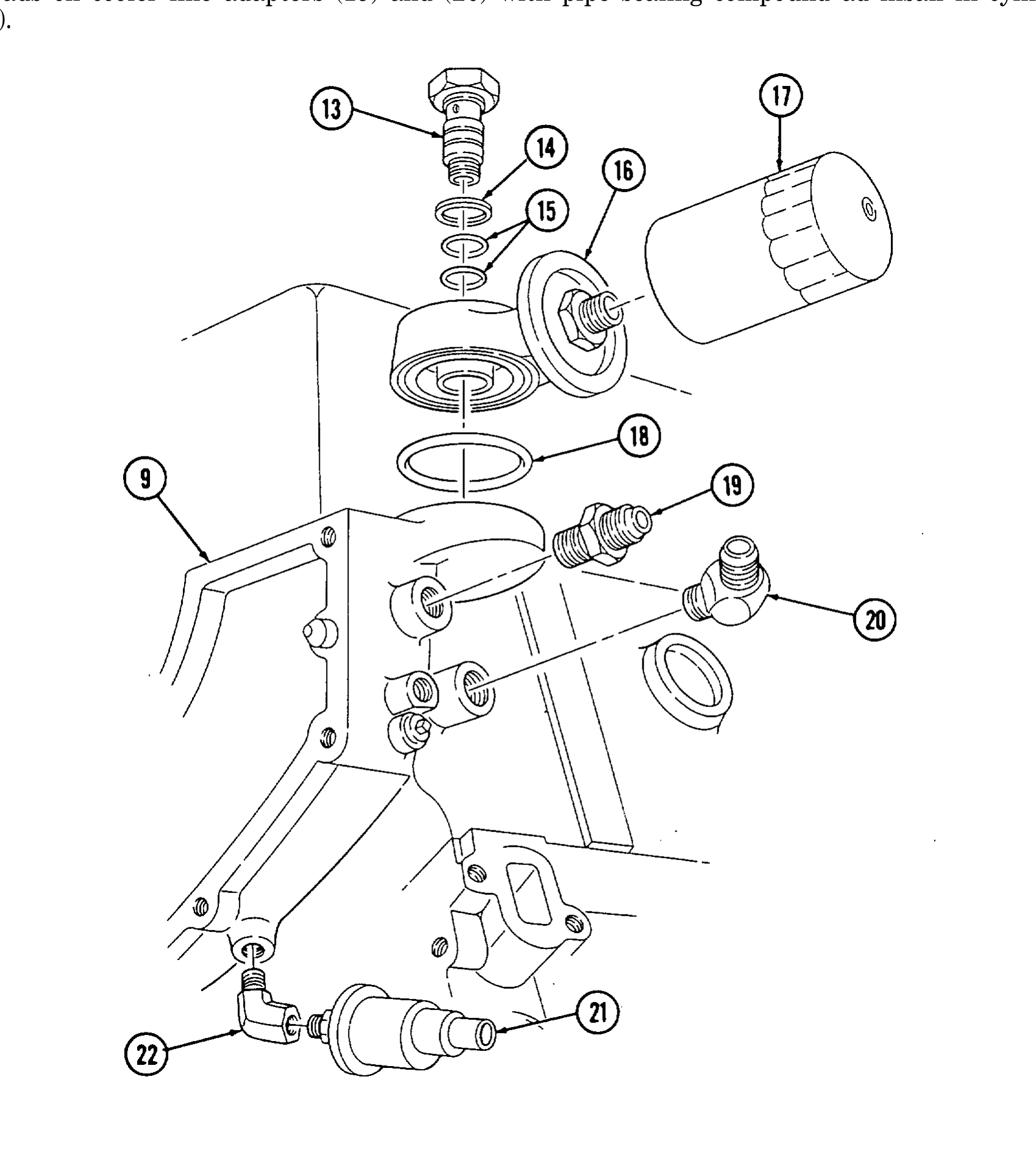
i. Oil Filter and Adapter
1. Install two O-rings (15) on adapter bolt (13).
2. Install O-ring (18) on adapter (16).
3. Install adapter (16) on cylinder block (9) with adapter bolt (13) and gasket (14). Tighten adapter bolt (13) to 40 lb-ft (54 N•m).
4. Install oil filter (17) on adapter (16). Tighten oil filter (17) until gasket contacts adapter (16) and tighten an additional 1/2 to 3/4 turn.
5. Coat threads on fitting (22) with pipe sealing compound and install in cylinder block (9).
6. Coat threads on oil pressure sending unit (21) with pipe sealing compound and install in fitting (22).
7. Coat threads on cooler line adapters (19) and (20) with pipe sealing compound ad insall in cylinder. block (9).
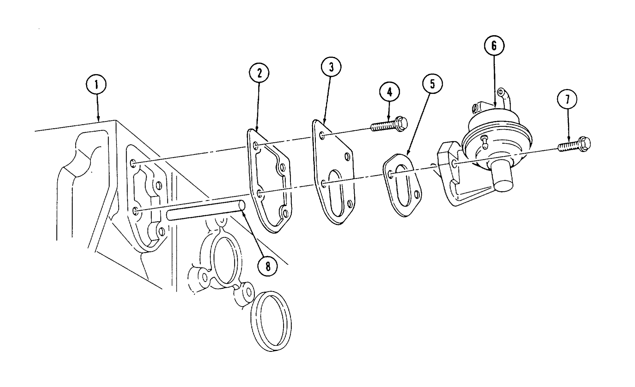
j. Fuel Pump
1. Apply OE/HDO to pushrod (8) and install into cylinder block (1).
2. Install gasket (2) and adapter plate (3) on cylinder block (1) with two capscrews (4). Tighten capscrews (4) to 48-84 lb-in. (5-10 N•m).
3. Install gasket (5) and fuel pump (6) on adapter plate (3) with two capscrews (7). Tighten capscrews (7) to 20-30 lb-ft (27-41 N•m).
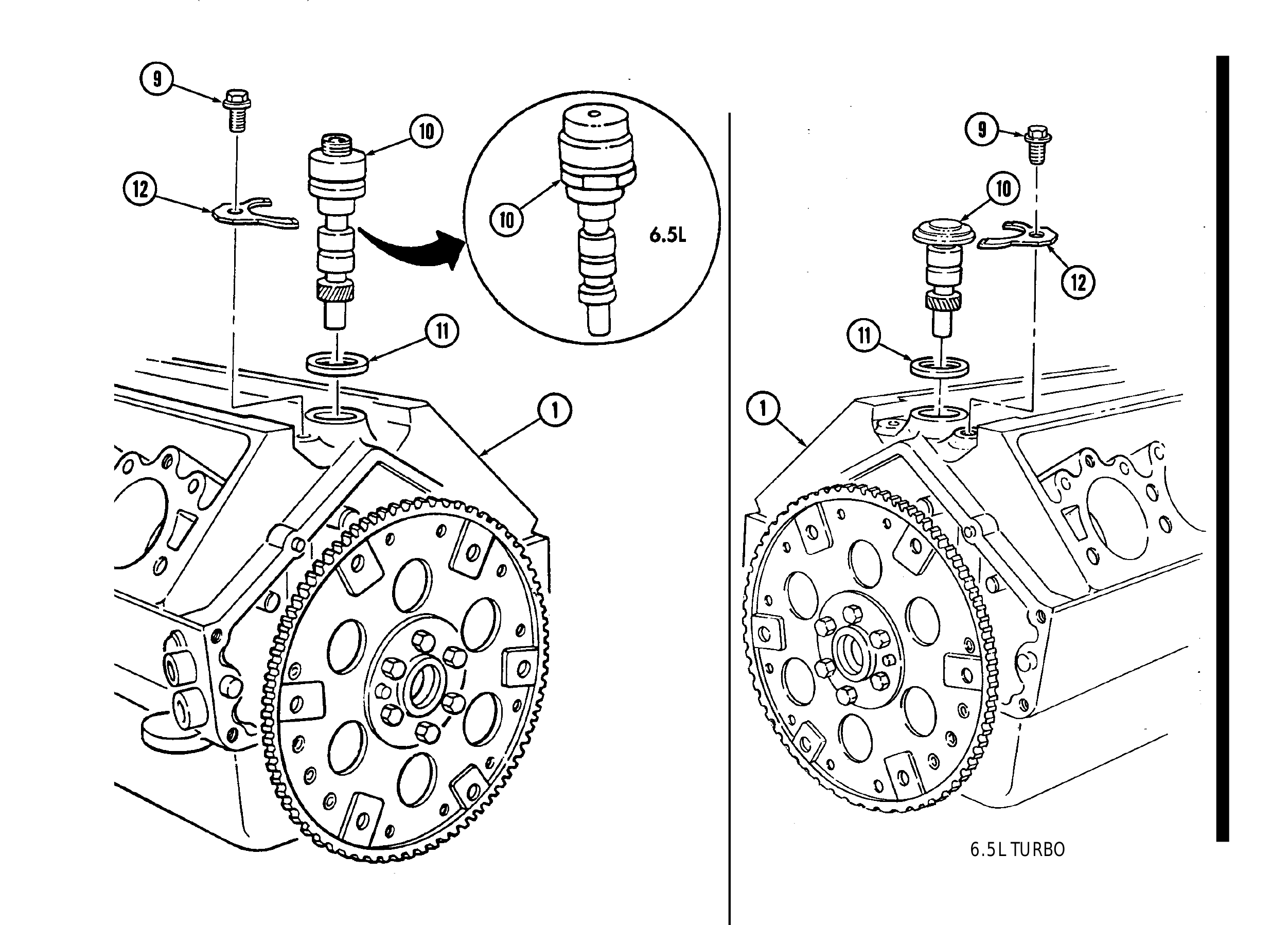
k. Oil Pump Drive
1. Rotate cylinder block (1) 180 degrees.
2. Install gasket (11) and oil pump drive (10) into cylinder block (1).
3. Secure oil pump drive (10) with clamp (12) and capscrew (9). Tighten capscrew (9) to 25-37 lb-ft (34-50 N•m).
6.5L TURBO
l. Fuel Injection Pump
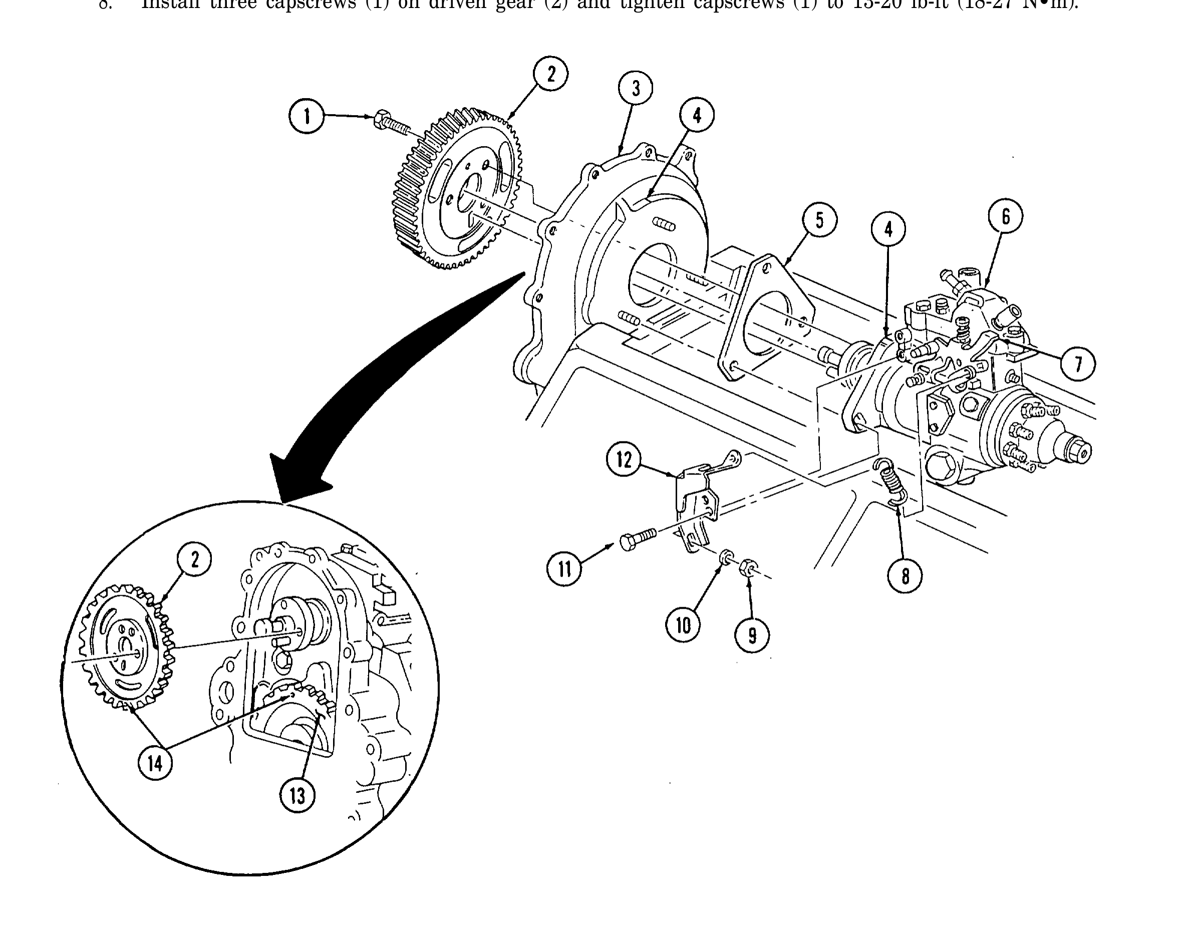
1. Install gasket (5) and injection pump (6) on timing gear cover (3).
2. Install accelerator cable bracket (12) on fuel injection pump (6) with two capscrews (11). Tighten capscrews (11) to 13 lb-ft (18 N•m).
3. Install idle return spring (8) on throttle lever (7) and accelerator cable bracket (12).
4. Align timing marks (4) on injection pump (6) and timing gear cover (3).
5. Install injection pump (6) to timing gear cover (3) with three washers (10) and nuts (9).
6. Rotate crankshaft until timing mark (14) on pump drive gear (13) is straight up.
7. Align timing marks (14) on pump drive gear (13) and pump driven gear (2) and install driven gear (2) into timing gear cover (3).
8. Install three capscrews (1) on driven gear (2) and tighten capscrews (1) to 13-20 lb-ft (18-27 N•m).
m. Water Pump and Adapter Plate
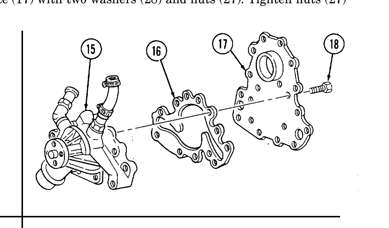
1. Install gasket (16) and water pump (15) on adapter plate (17) with seven capscrews (18). Tighten capscrews (18) to 13-20 lb-ft (18-27 N•m).
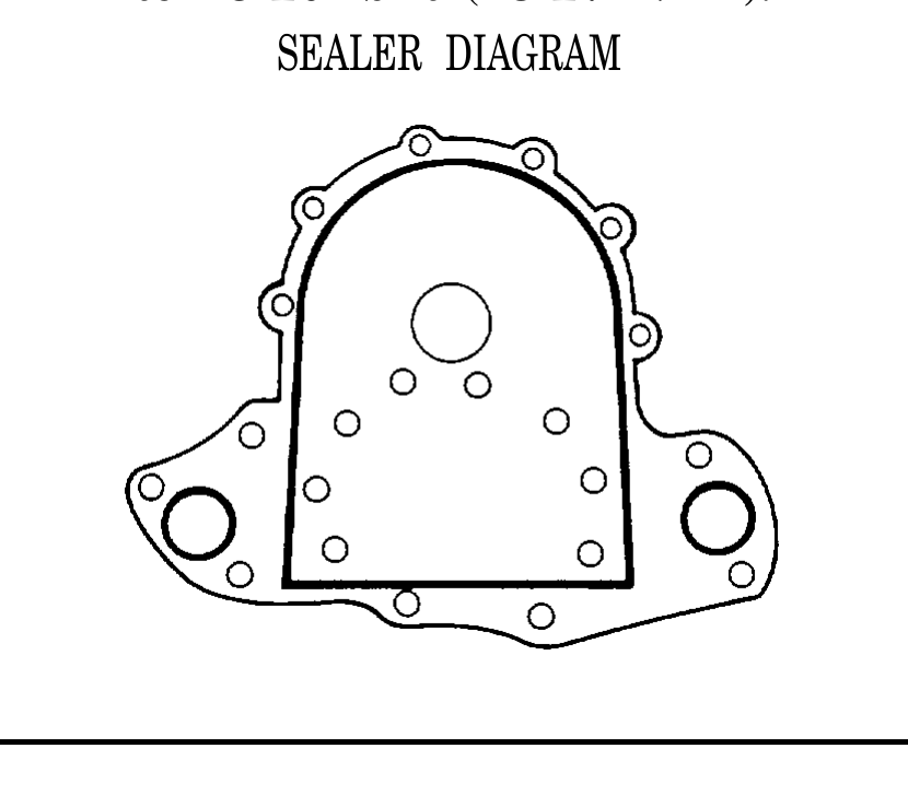
2. Apply sealer to sealing surfaces on adapter plate (17), following diagram shown.
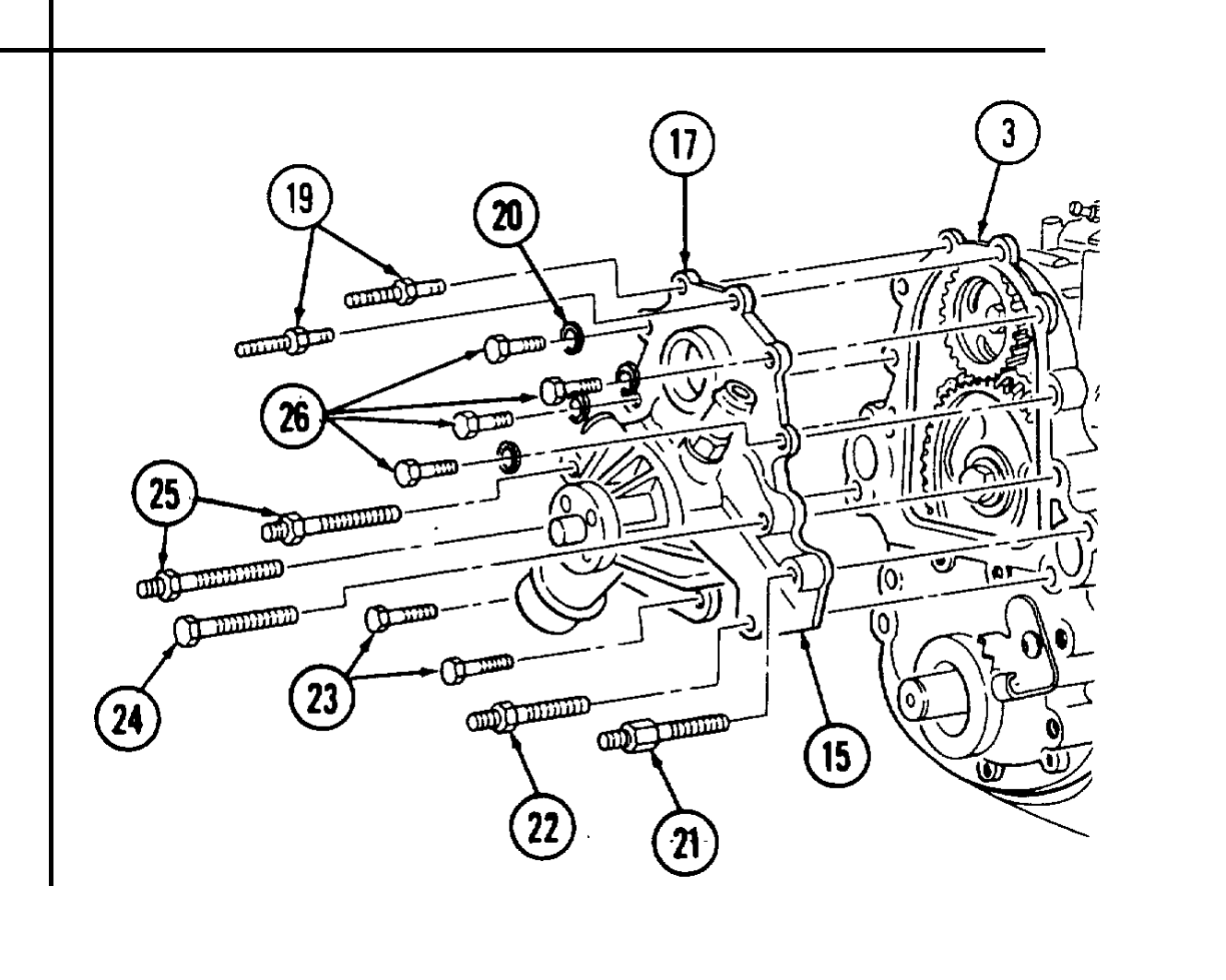
3. Apply pipe sealing compound to capscrews (24) and (23).
4. Install adapter plate (17) and water pump (15) on timing gear cover (3) with two long studs (25), short stud with thick hex (21), stud (22), and capscrew (24).
5. Install two long capscrews (23), studs (19), four washers (20), and capscrews (26). Tighten studs (19) and capscrews (26) and (23) to 13-20 lb-ft (18-27 N•m). Tighten studs (21), (22), and (25), and capscrew (24) to 24-37 lb-ft (34-50 N•m).
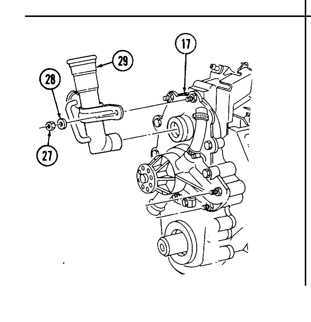
6. Install oil fill tube (29) on adapter plate (17) with two washers (28) and nuts (27). Tighten nuts (27) to 13-20 lb-ft (18-27 N•m). SEALER DIAGRAM
n. Valve Lifters
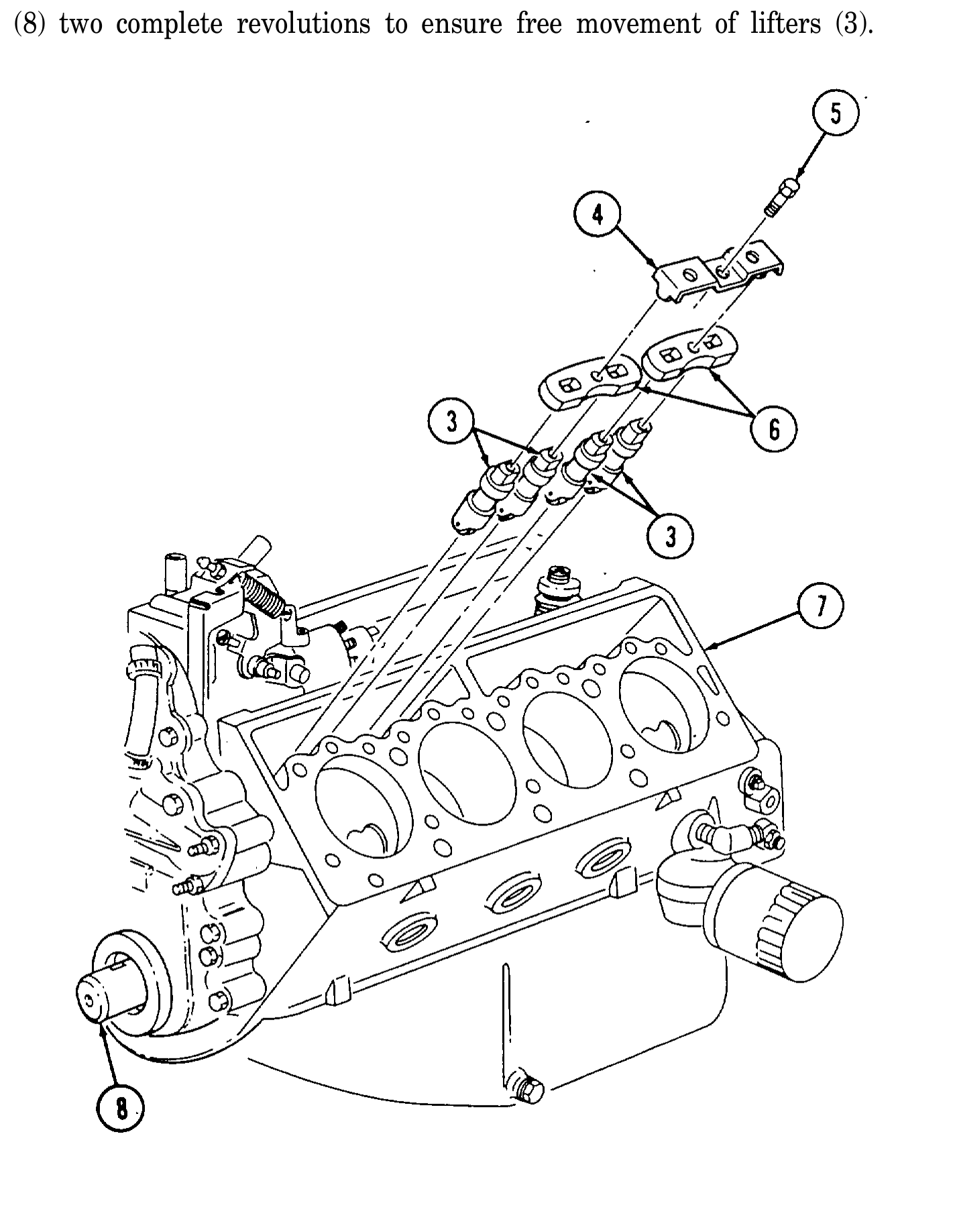
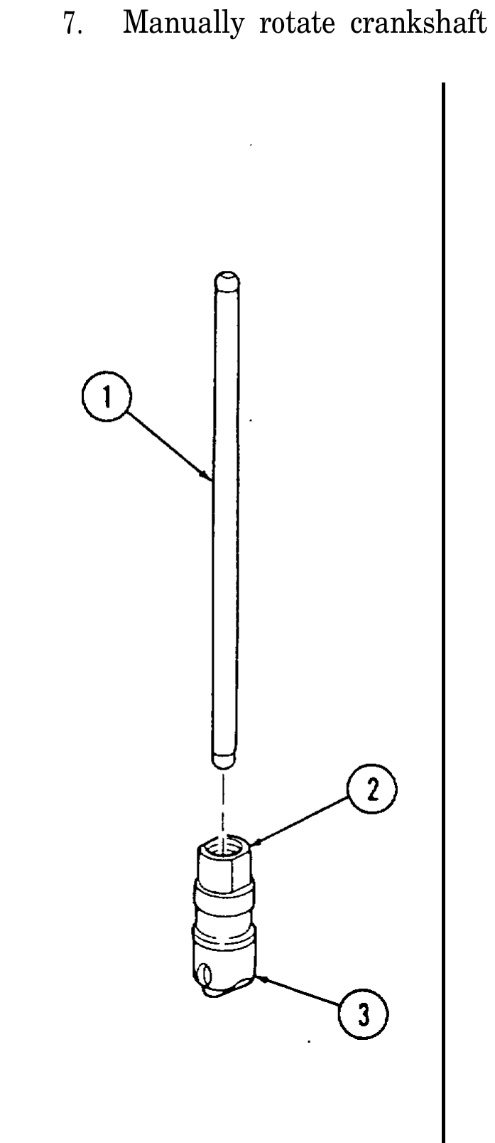
1. Submerge eight lifters (3) in clean diesel fuel or kerosene and work plunger (2) up and down with pushrod (1) to prime lifters (3).
2. Apply OE/HDO to lifters (3).
3. Install lifters (3) into cylinder block (7).
4. Install four guide plates (6) on lifters (3).
5. Install two guide plate clamps (4) with two capscrews (5). Tighten capscrews (5) to 15-20 lb-ft (20-27 N•m).
6. Repeat steps 1 through 5 for opposite side.
7. Manually rotate crankshaft (8) two complete revolutions to ensure free movement of lifters (3).
o. Cylinder Heads
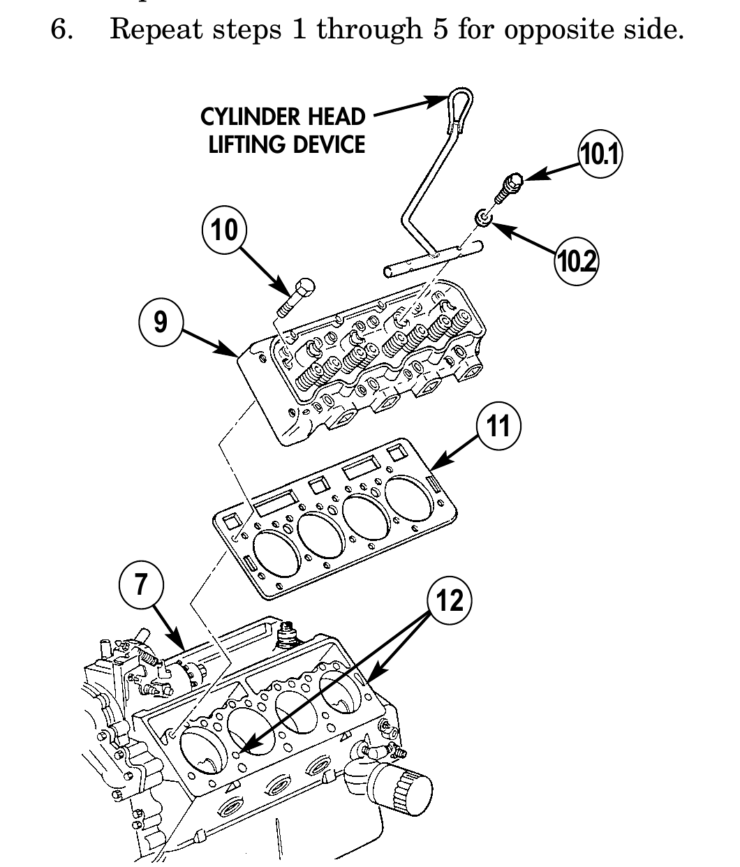
1. Install head gasket (11) over dowel pins (12) on cylinder block (7).
1.1. Install cylinder head lifting device on center of cylinder head (9) with two washers (10.2) and capscrews (10.1).
1.2. Install cylinder head (9) on cylinder block (7) and remove two capscrews (10.1), washers (10.2), and cylinder head lifting device.
2. Clean threads of capscrews (10) with a wire brush to remove old pipe sealing compound. Apply pipe sealing compound to threads and under heads of capscrews (10).
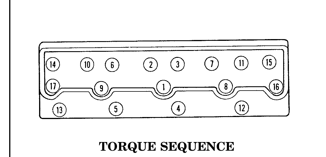
3. Install cylinder head (9) on cylinder block (7) with seventeen capscrews (10). Tighten capscrews (10) to 20 lb-ft (27 N•m), following torque sequence shown.
4. For 6.2 L engine, tighten seventeen capscrews (10) to 50 lb-ft (68 N•m), following torque sequence shown. 4.1 For 6.5 L engine, tighten seventeen capscrews (10) to 55 lb-ft (75 N•m), following torque sequence shown. 4.2 For 6.5 L engine, retighten seventeen capscrews (10) to 55 lb-ft (75 N•m), following torque sequence shown.
5. Tighten seventeen capscrews (10) an additional 90°, following torque sequence shown and mark capscrews (10).
6. Repeat steps 1 through 5 for opposite side.
CYLINDER HEAD LIFTING DEVICE 10.1
TORQUE SEQUENCE
p. Glow Plugs
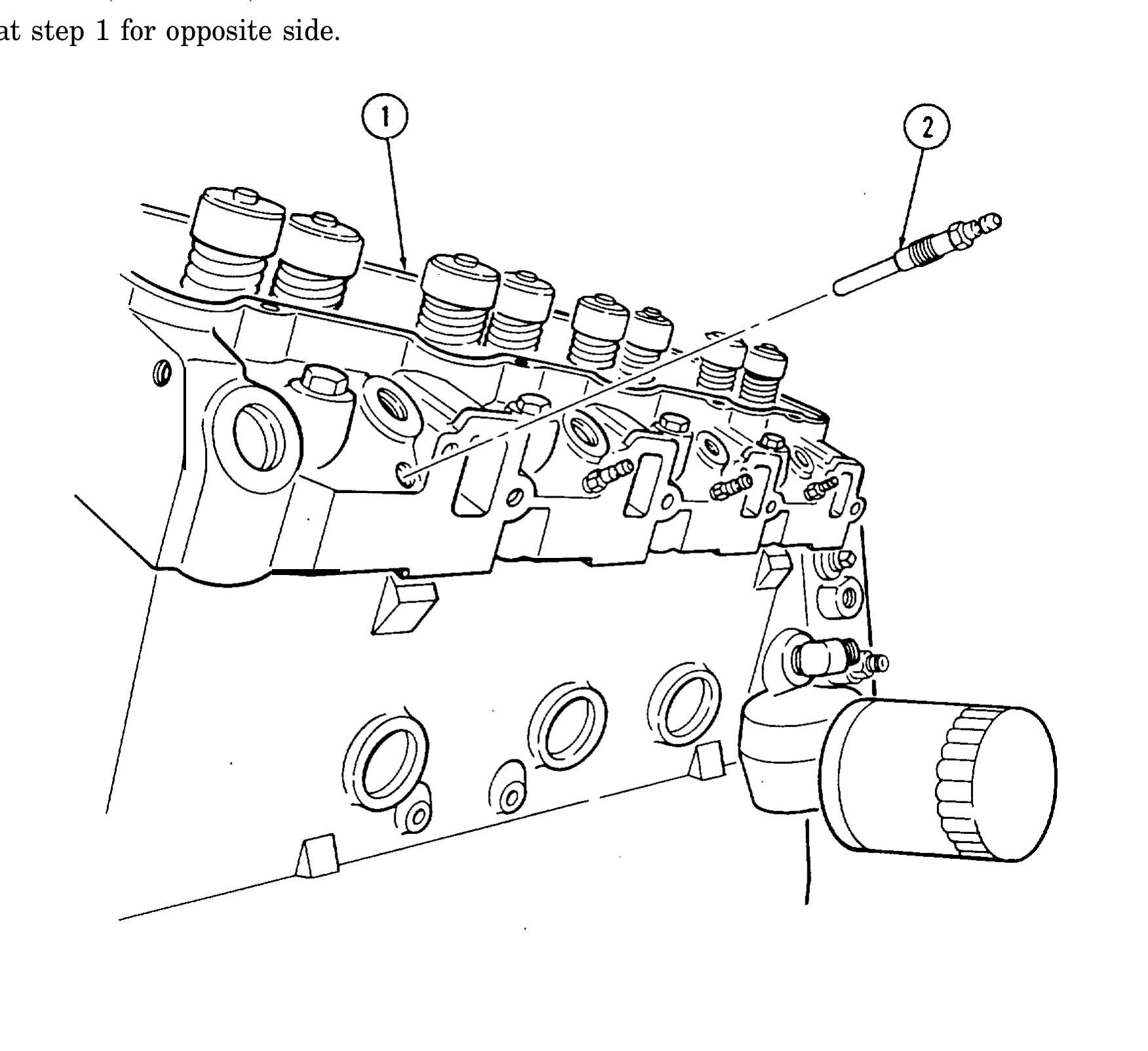
1. Install four glow plugs (2) into cylinder head (l). Using glow plug socket, tighten glow plugs (2) to 8-12 lb-ft (11-16 N•m).
2. Repeat step 1 for opposite side.
q. Fuel Injection Nozzles
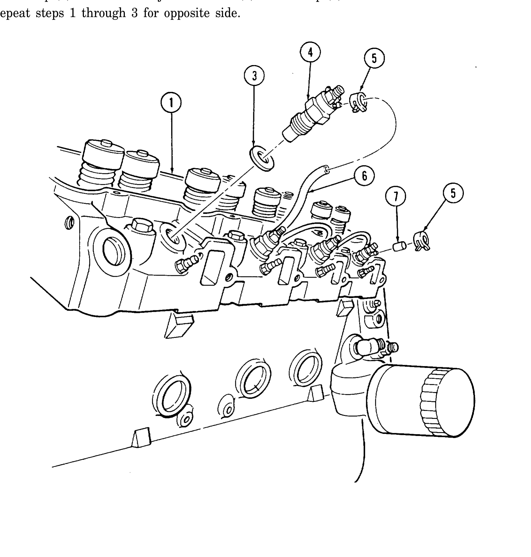
1. Install four gaskets (3) and fuel injection nozzles (4) into cylinder head (1). Using injector nozzle socket, tighten fuel injection nozzles (4) to 44-60 lb-ft (60-81 N•m).
2. Install three hoses (6) on fuel injection nozzles (4) with six clamps (5).
3. Install cap (7) on rear fuel injection nozzle (4) with clamp (5).
4. Repeat steps 1 through 3 for opposite side.
r. Rocker Arm Shaft and Pushrods
Marked ends of pushrods must point up when installed or engine damage may result.
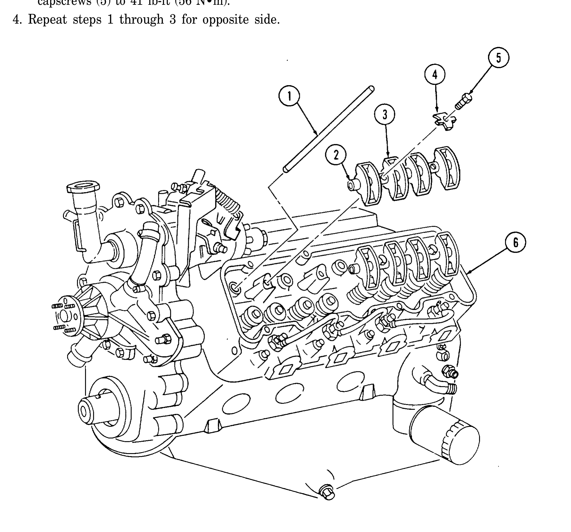
1. Install eight pushrods (1) in proper location with marked end of pushrods (1) up. Make sure pushrods (1) are properly seated.
2. Install two rocker arm and shaft assemblies (2) on cylinder head (6). Make sure pushrods (1) properly seat in rocker arms (3).
3. Secure rocker arm and shaft assemblies (2) with four retainers (4) and capscrews (5). Tighten capscrews (5) to 41 lb-ft (56 N•m).
4. Repeat steps 1 through 3 for opposite side.
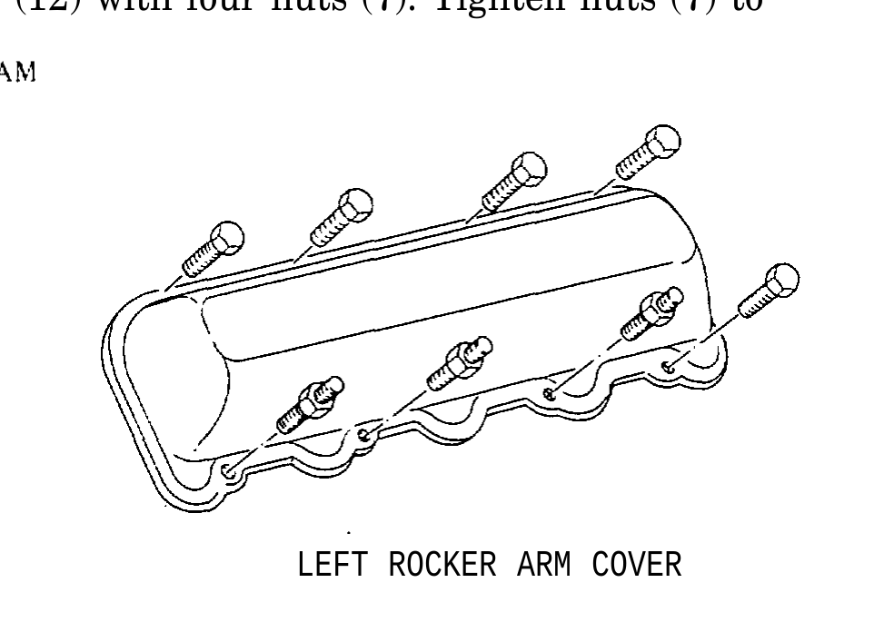
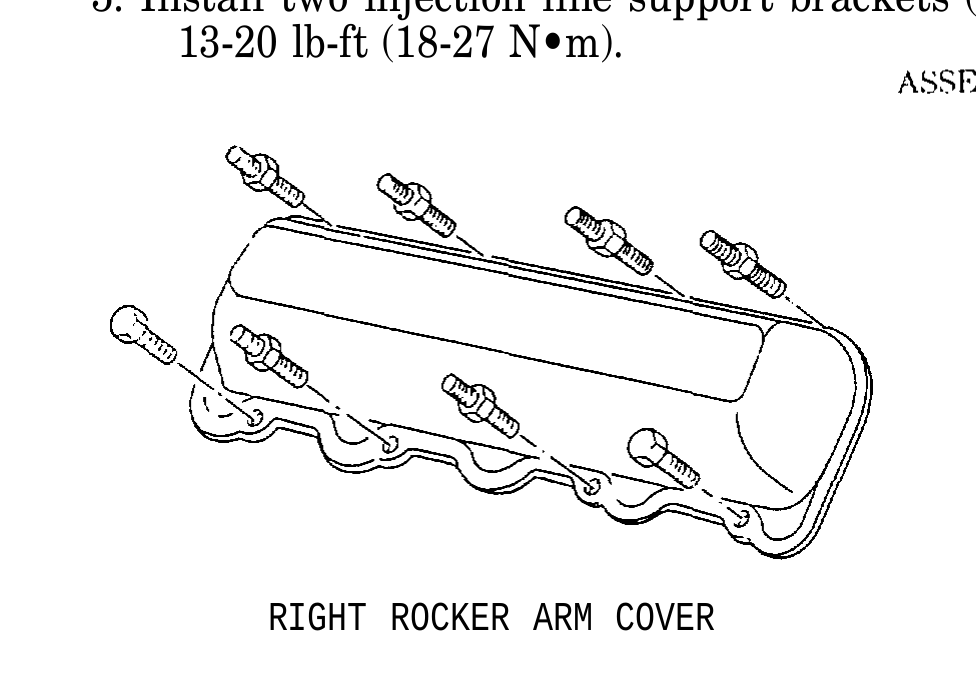
s. Rocker Arm Covers
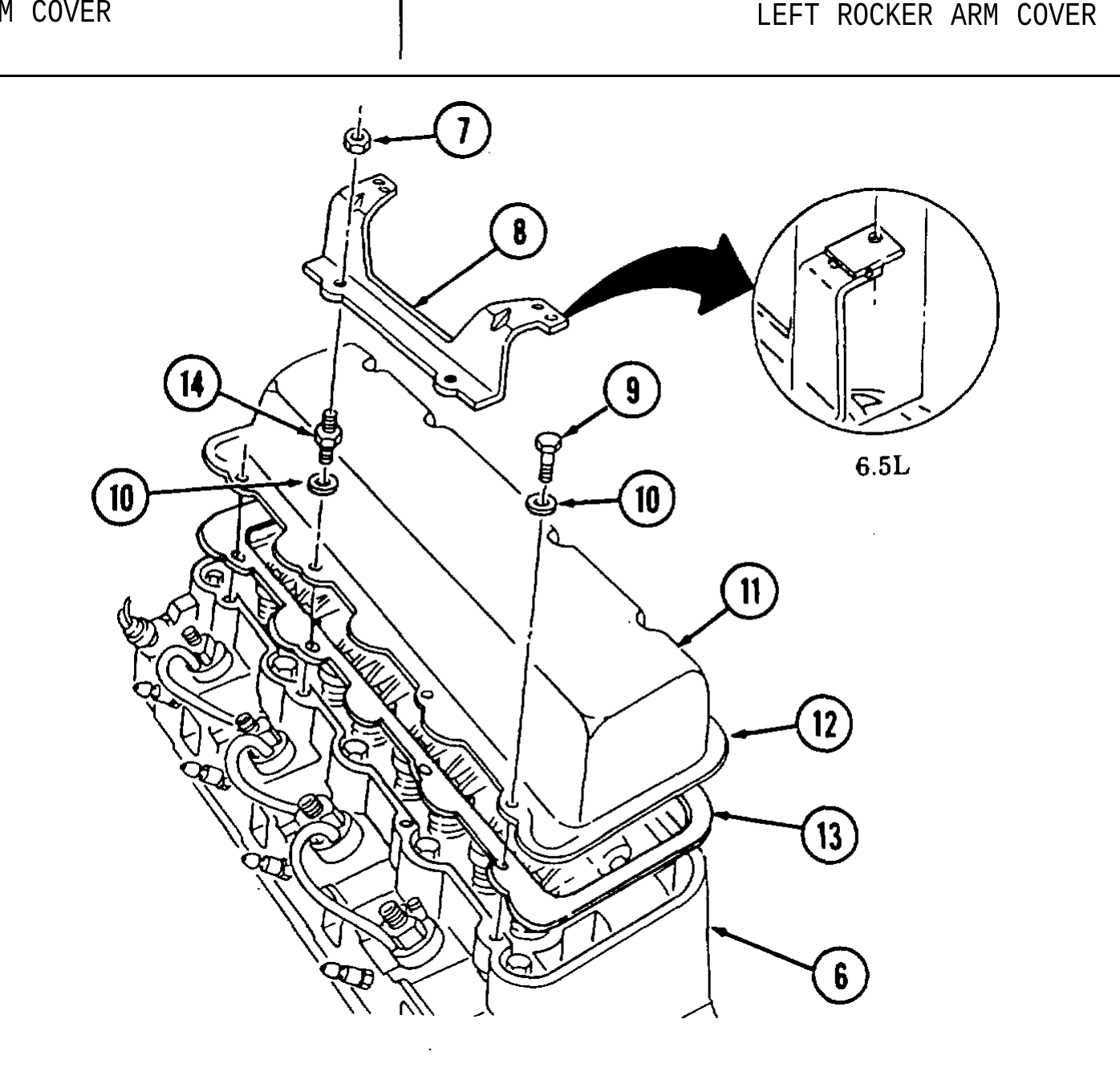
● If installing new rocker arm cover gaskets, perform step 1, then step 3. ● Silicone sealant can be used with the gasket, but is not required.
1. Install rocker arm cover gasket (13) on lip of cover (12) and align with capscrew holes.
2. Apply a 1/16-in. (4 mm) bead of silicone sealant around sealing surface of rocker arm covers (11).
3. Install rocker arm covers (11) on cylinder head (6) with sixteen washers (10), seven capscrews (9), and nine studs (14), following assembly diagram.
4. Tighten capscrews (9) and studs (14) to 13-25 lb-ft (18-34 N•m).
5. Install two injection line support brackets (8) on studs (12) with four nuts (7). Tighten nuts (7) to 13-20 lb-ft (18-27 N•m).
RIGHT ROCKER ARM COVER LEFT ROCKER ARM COVER
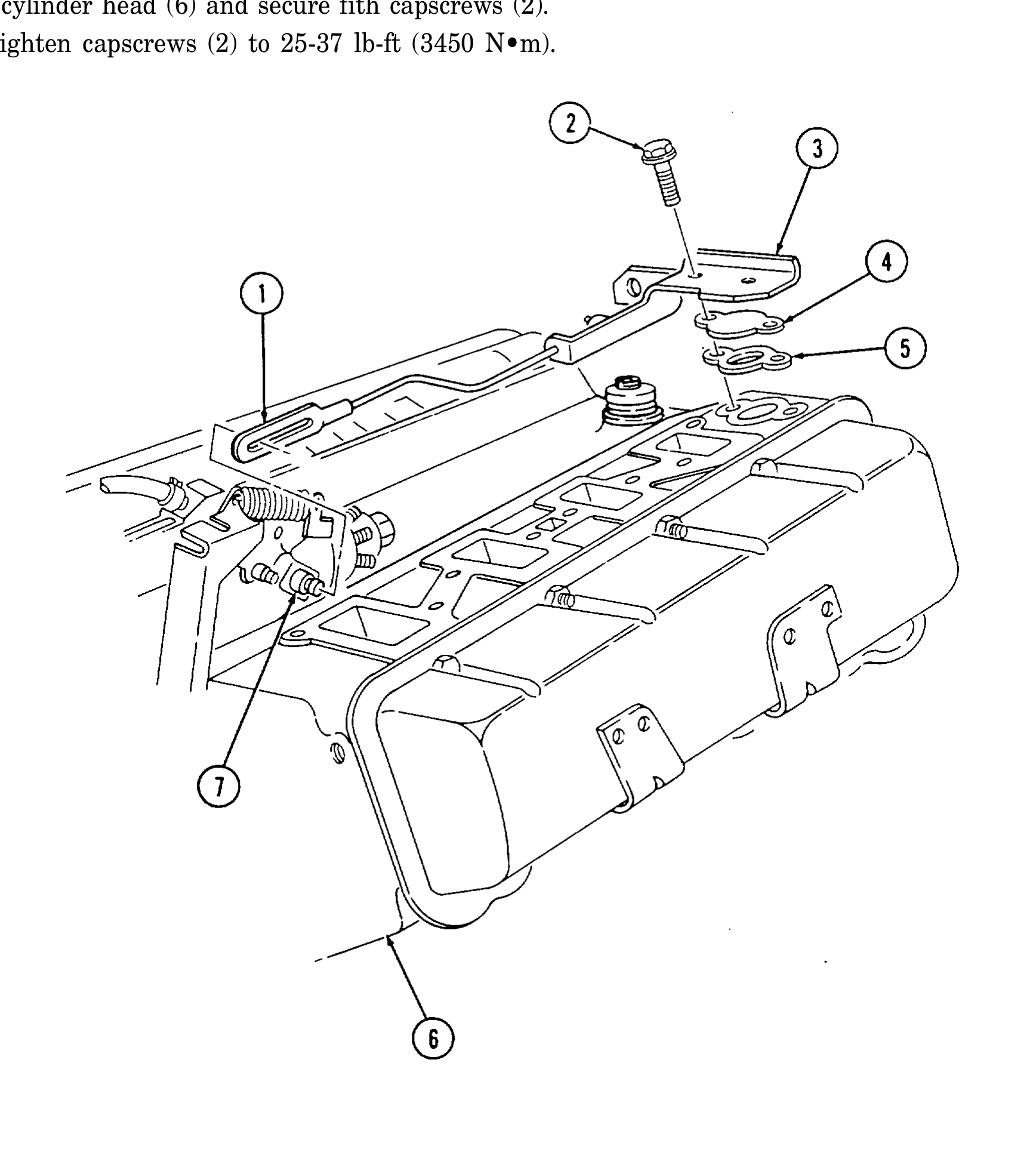
t. Modulator Link
1. Attach modulator link (1) to throttle lever (7).
2. Install water jacket cover gasket (5), water jacket cover (4), and modulator link bracket (3) on cylinder head (6) and secure fith capscrews (2).
3. Tighten capscrews (2) to 25-37 lb-ft (3450 N•m).
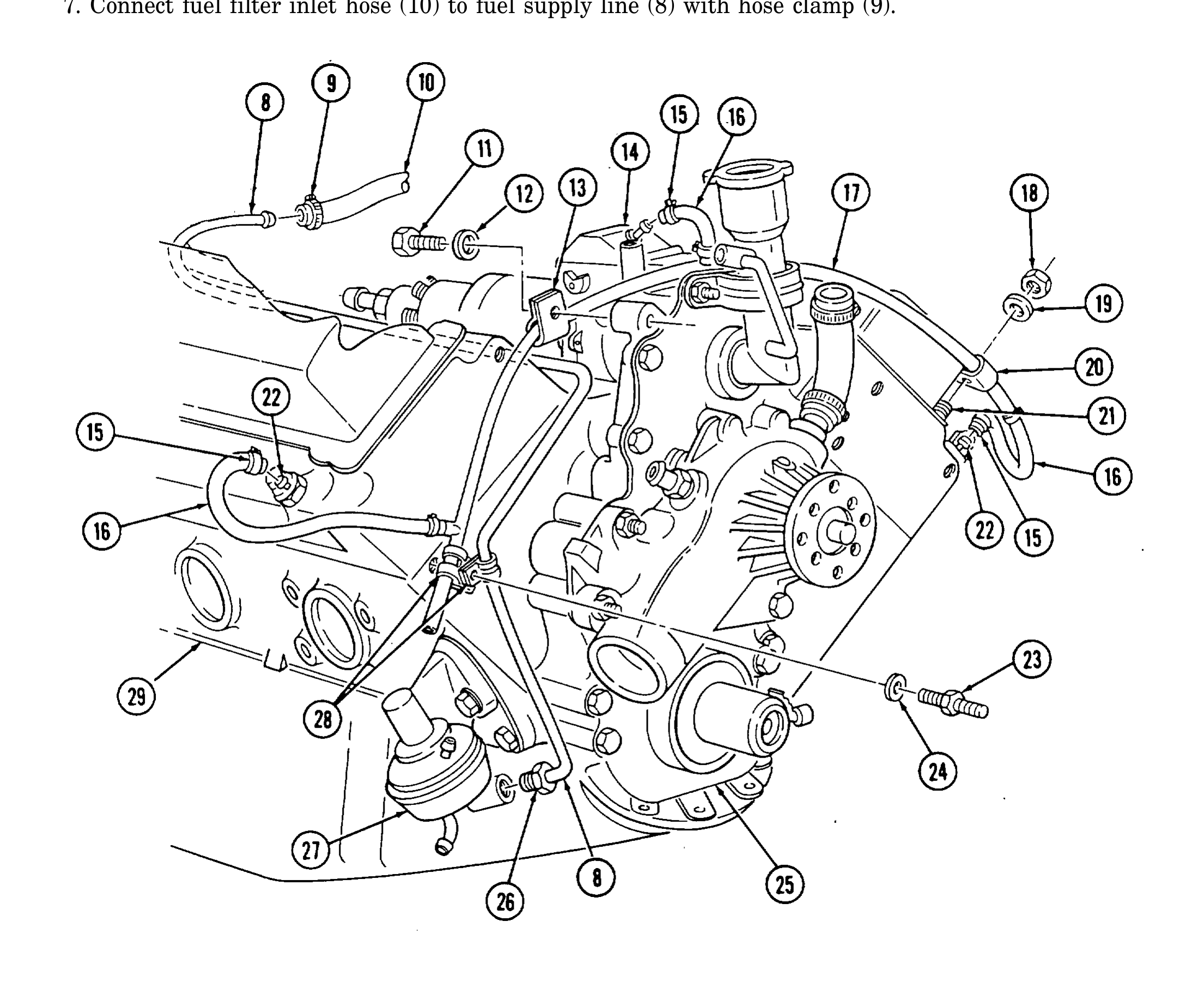
u. Fuel Supply and Return Lines
1. Install fuel supply line (8) on fuel pump (27) and finger tighten tube nut (26).
2. Install fuel return line (17) on timing gear cover (25) with clamp (13), washer (12), and capscrew (11). Finger tighten capscrew (11).
3. Install return line (17) to valve cover stud (21) with clamp (20), washer (19), and nut (18). Tighten nut (18) to 13-20 lb-ft (18-27 N•m). 4, Install supply line (8) and return line (17) to cylinder block (29) with two clamps (28), washer (24), and stud (23). Tighten stud (23) and capscrew (11) to 25 lb-ft (34 N•m).
5. Tighten tube nut (26).
6. Connect three rubber hoses (16) to front fuel injection nozzles (22) and fuel injection pump (14) with, three clamps (15).
7. Connect fuel filter inlet hose (10) to fuel supply line (8) with hose clamp (9).
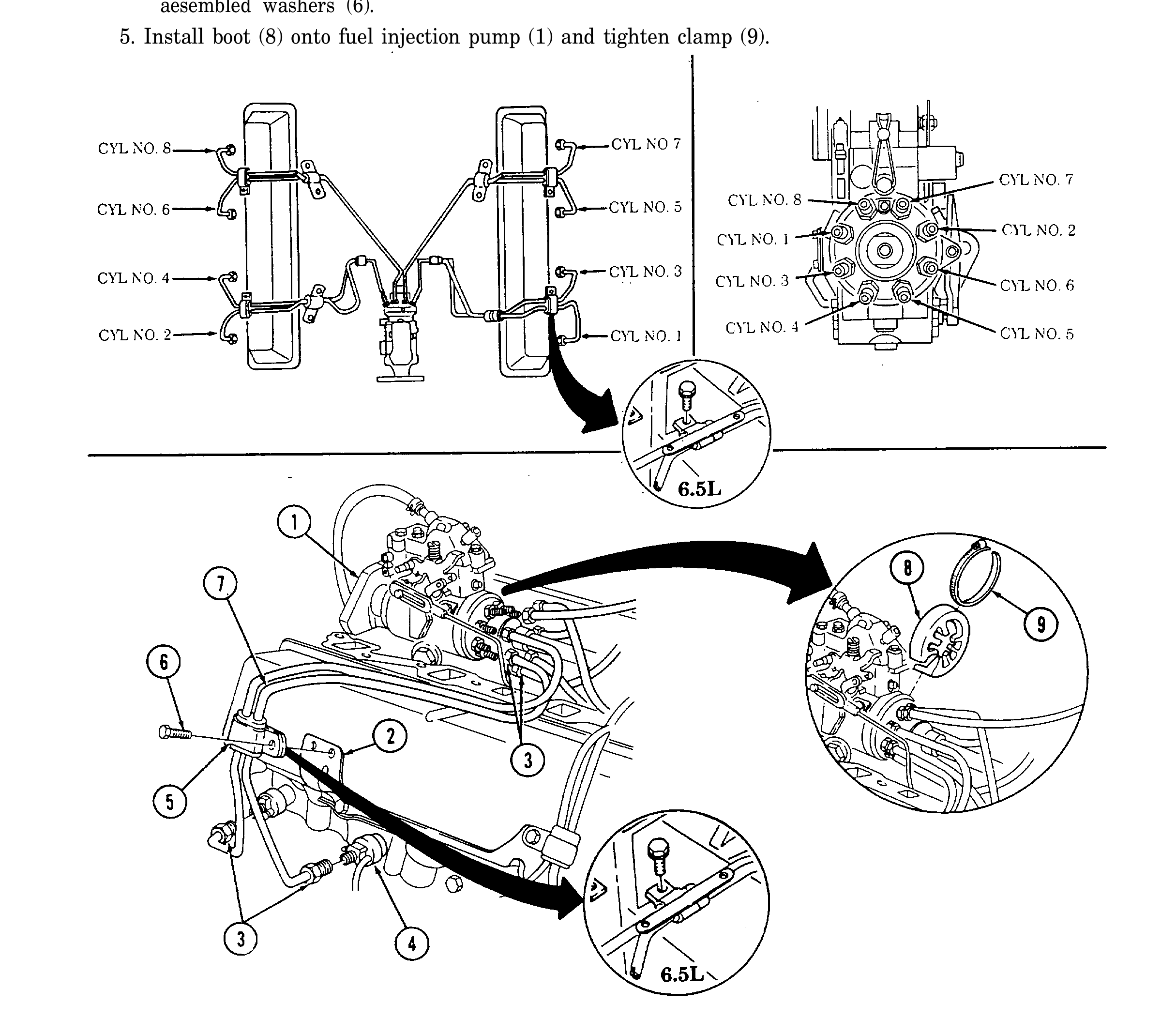
v. Fuel Injection Lines
1. Install number 1 and 3 injection lines (7) and connect tO fuel injection pump (1) and fuel injection nozzles (4).
2. Using crowfoot wrenches, tighten four nuts (3) and fuel injection lines (7) on fuel injection nozzles (4) and fuel injection pump (1) to 20 lb-ft (27 N•m).
3. Repeat steps 1 and 2 for each set of remaining fuel injection lines (7), number 5 and 7, number 6 and 8, and number 2 and 4.
4. Install four clamps (5) securing fuel injection lines (7) to support brackets (2) with four screw- aesembled washers (6).
5. Install boot (8) onto fuel injection pump (1) and tighten clamp (9).
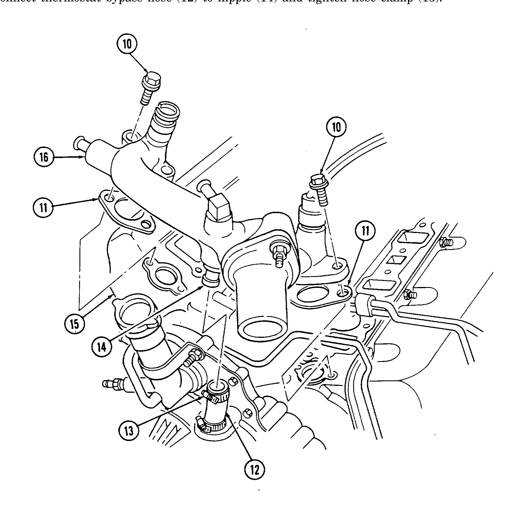
w. Water Crossover
1. Install two gaskets (11) and water crossover (16) on cylinder heads (15).
2. Install four capscrews (10) on water crossover (16) and cylinder heads (15). Tighten capscrews (10) tO 25-37 lb-ft (34-50 N•m).
3. Connect thermostat bypass hose (12) to nipple (14) and tighten hose clamp (13).
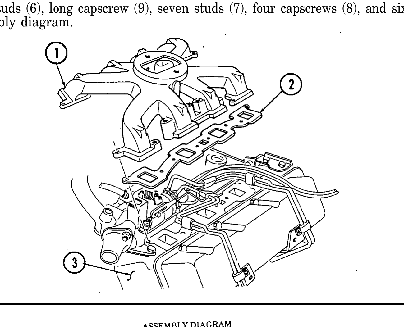
x. Intake Manifold
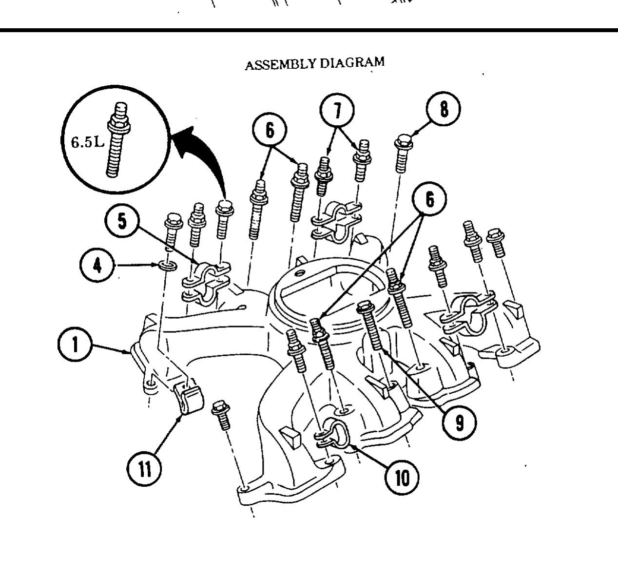
1. Install two gaskets (2) and intake manifold (1) on cylinder heads (3).
2. Install injection line clip (10), three injection line clips (5), and fuel supply line clamp (11) on intake manifold (1), following assembly diagram shown.
3. Install four long studs (6), long capscrew (9), six studs (7), five capscrews (8), and sixteen washers (4), following assembly diagram shown.
4. Install four long studs (6), long capscrew (9), seven studs (7), four capscrews (8), and sixteen washers (4), following assembly diagram.
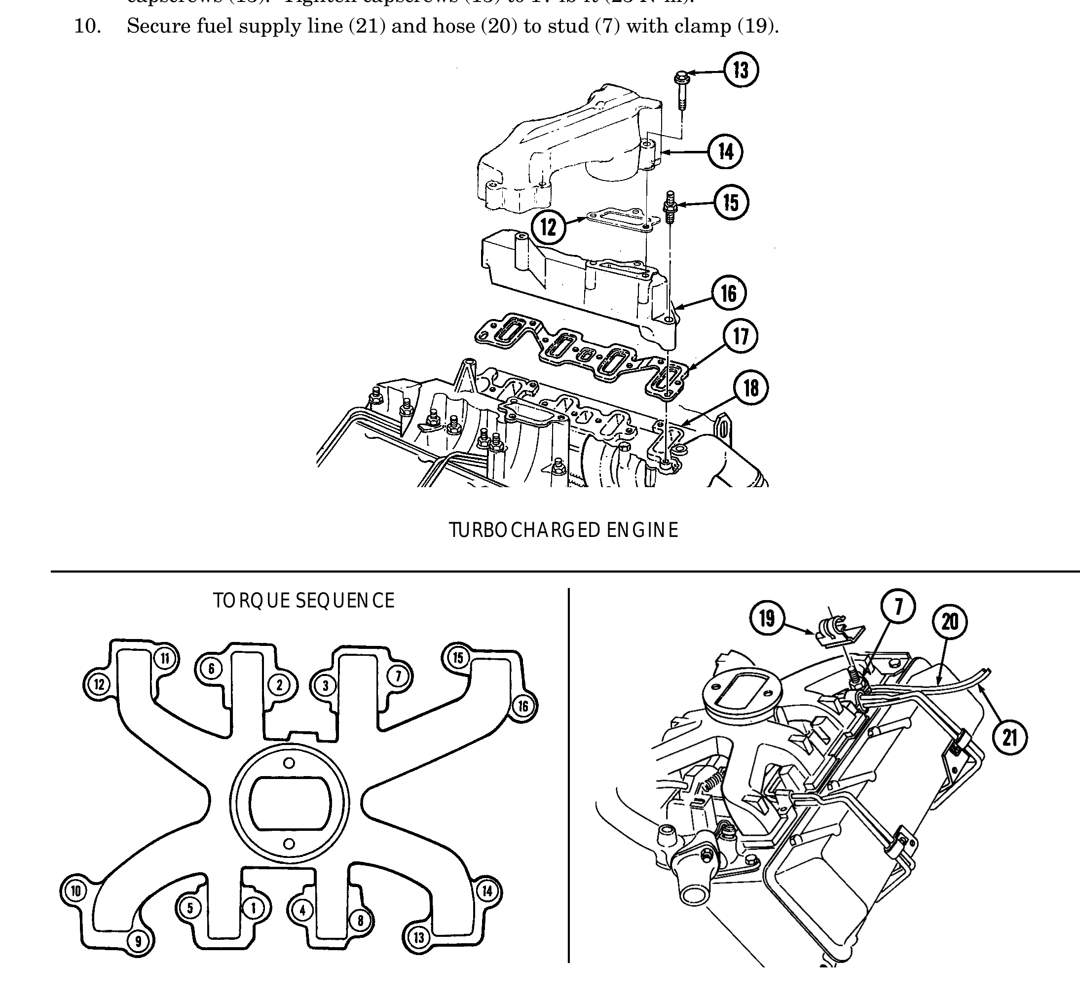
5. Tighten all studs (6) and (7) and capscrews (8) and (9) to 30 lb-ft (41 N•m), following torque sequence shown.
6. Install gasket (17) and intake manifold (16) on cylinder head (18) with eight studs (15).
7. Beginning at center of intake manifold (16) and working toward ends, tighten studs (15) to 30 lb-ft (41 N•m).
8. Repeat steps 6 and 7 for opposite side.
9. Install two gaskets (12) and center intake manifold (14) on intake manifolds (16) with six capscrews (13). Tighten capscrews (13) to 17 lb-ft (23 N•m).
10. Secure fuel supply line (21) and hose (20) to stud (7) with clamp (19).
TURBOCHARGED ENGINE
TORQUE SEQUENCE
y. Exhaust Manifolds
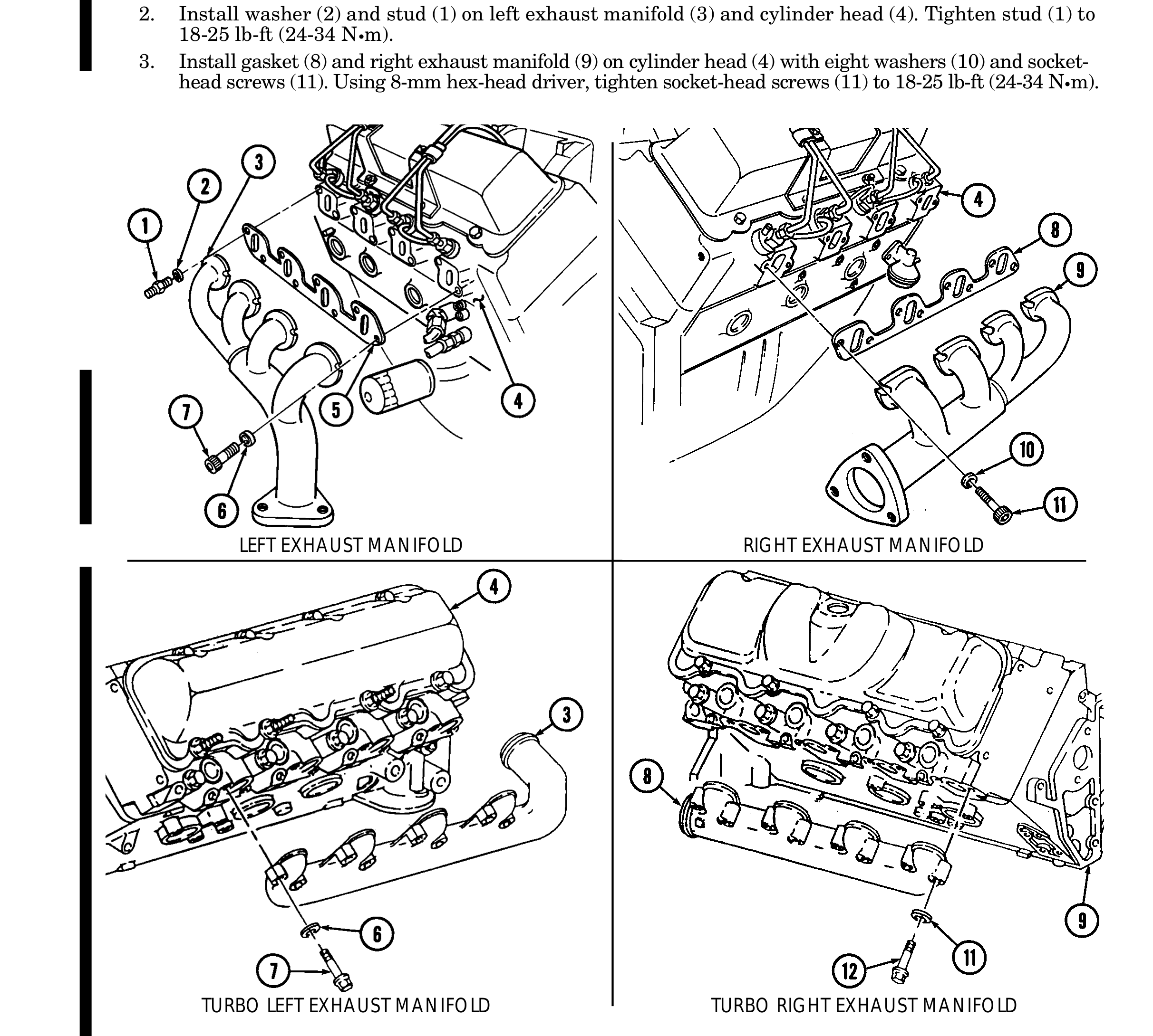
1. Install gasket (5) and left exhaust manifold (3) on cylinder head (4) with seven washers (6) and socket-head screws (7). Using 8-mm hex-head driver, tighten socket-head screws (7) to 18-25 lb-ft (24-34 N•m).
2. Install washer (2) and stud (1) on left exhaust manifold (3) and cylinder head (4). Tighten stud (1) to 18-25 lb-ft (24-34 N•m).
3. Install gasket (8) and right exhaust manifold (9) on cylinder head (4) with eight washers (10) and socket- head screws (11). Using 8-mm hex-head driver, tighten socket-head screws (11) to 18-25 lb-ft (24-34 N•m).
LEFT EXHAUST MANIFOLD RIGHT EXHAUST MANIFOLD
TURBO LEFT EXHAUST MANIFOLD TURBO RIGHT EXHAUST MANIFOLD
y.1. Turbocharger
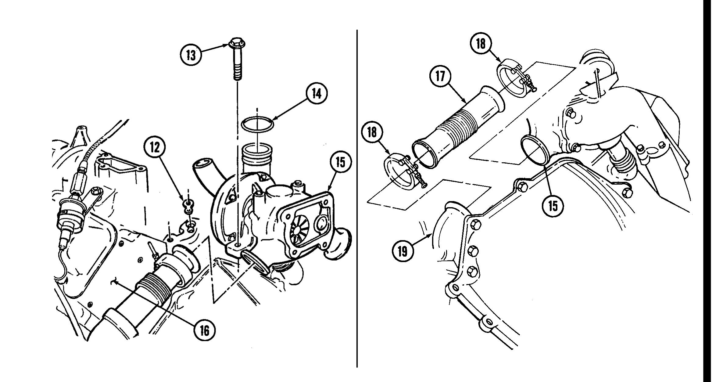
1. Install turbocharger oil gasket (12) and turbocharger (15) on engine block (16) with two capscrews (13).
2. Install O-ring (14) on turbocharger (15) outlet.
y.2. Manifold-to-Turbocharger Exhaust Pipe
1. Install two clamps (18) on exhaust pipe (17).
2. Install exhaust pipe (17) on turbocharger (15) and tighten clamp (18).
3. Install exhaust pipe (17) on exhaust manifold (19) and tighten clamp (18).
4. Repeat steps 1 through 3 for opposite side.
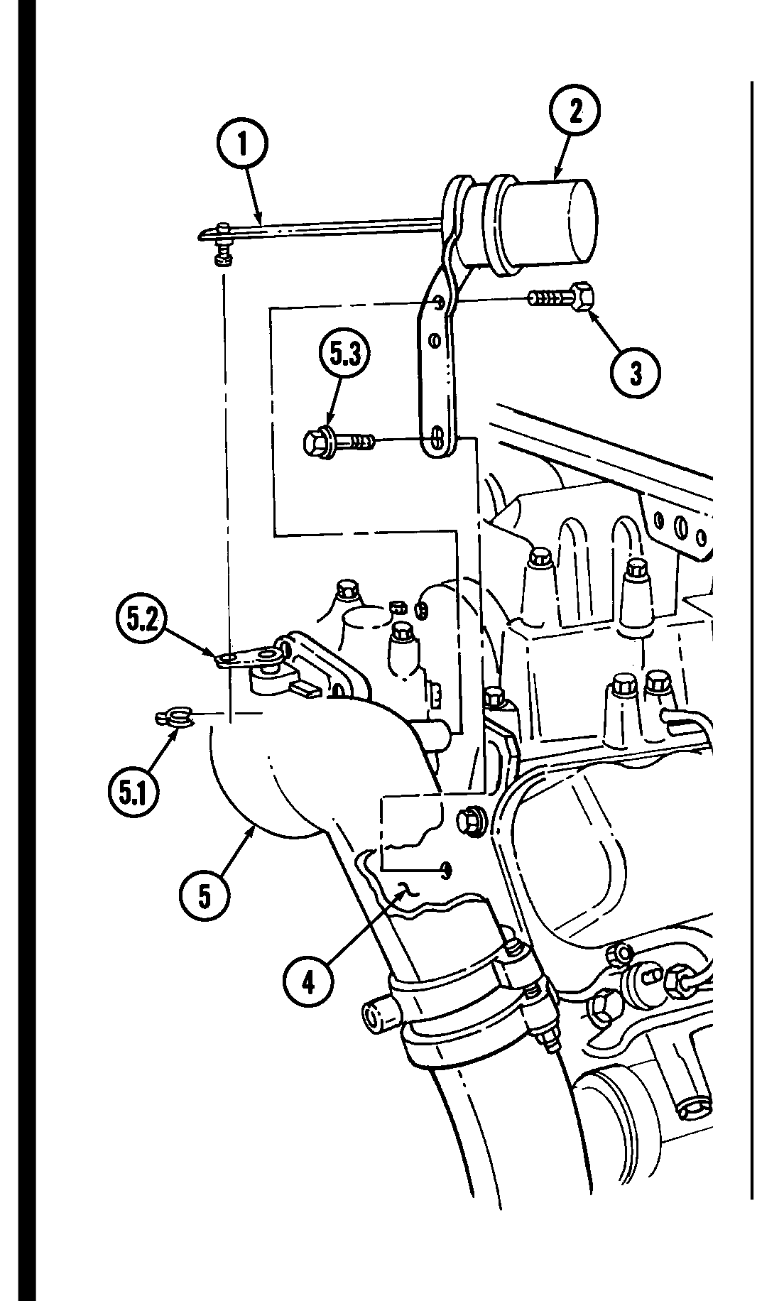
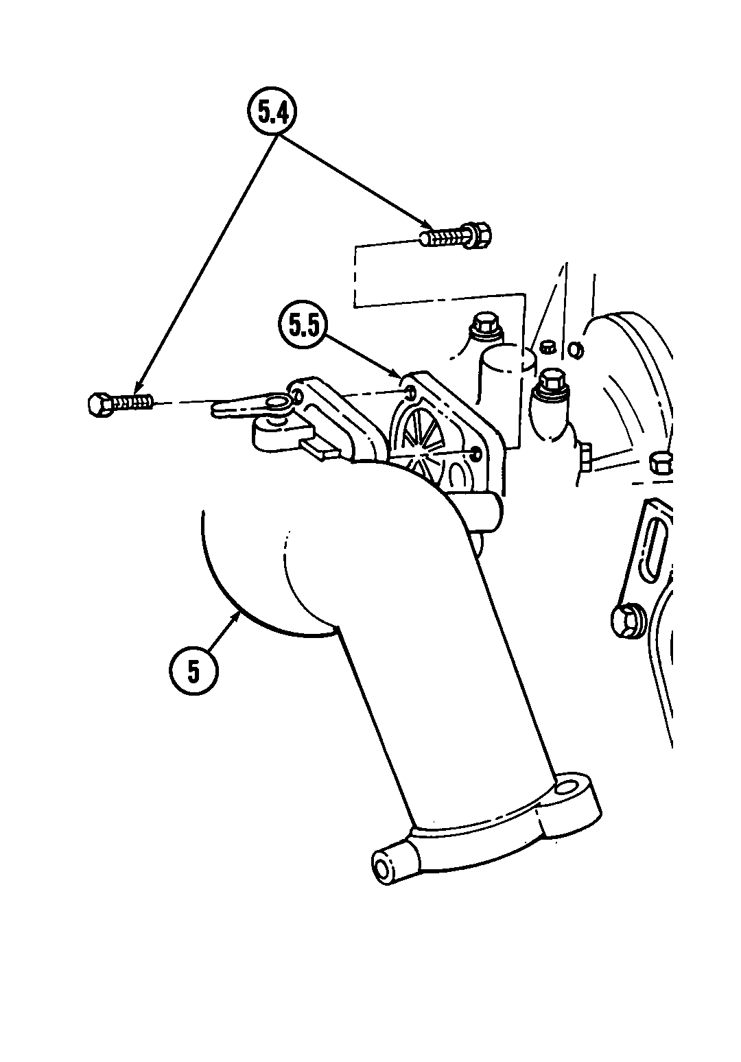
y.3. Wastegate Housing
Install wastegate housing (5) on turbocharger (5.5) with four capscrews (5.4).
y.4. Wastegate Actuator
1. Install wastegate actuator (2) on cylinder head (4) with capscrew (5.3).
2. Install wastegate actuator (2) on wastegate housing (5) with two capscrews (3).
3. Install actuator rod (1) on wastegate bellcrank (5.2) with clip (5.1).
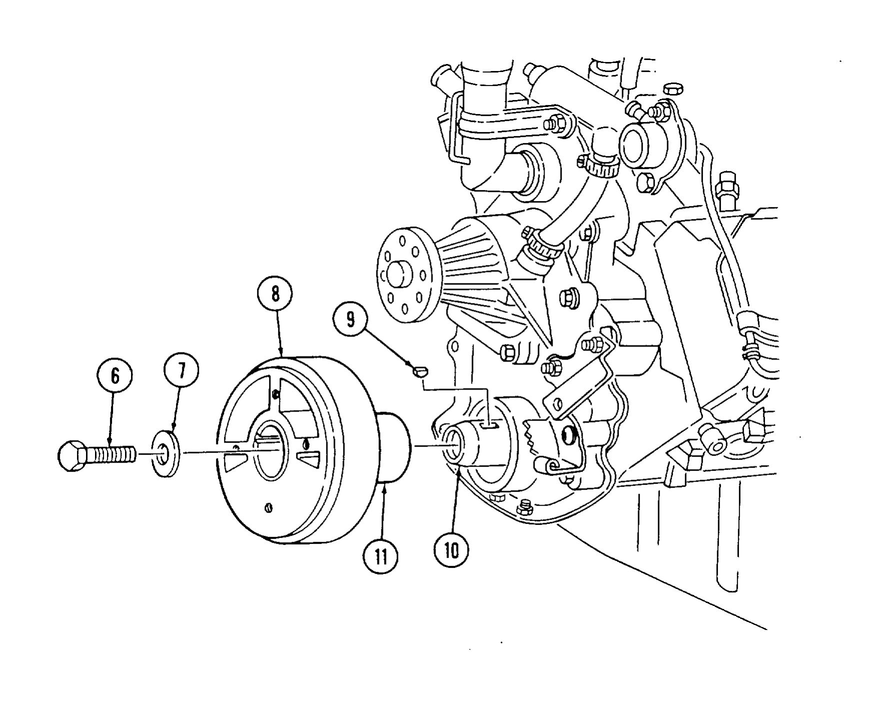
z. Torsional Damper
1. Install woodruff key (9) in crankshaft (10).
2. Apply lubricating oil to seal surface (11) on torsional damper (8).
3. Install torsional damper (8) on crankshaft (10) far enough to install washer (7) and capscrew (6). 4, Hold flywheel stationary with pry bar and tighten capscrew (6) to 140-162 lb-ft (190-220 N•m).
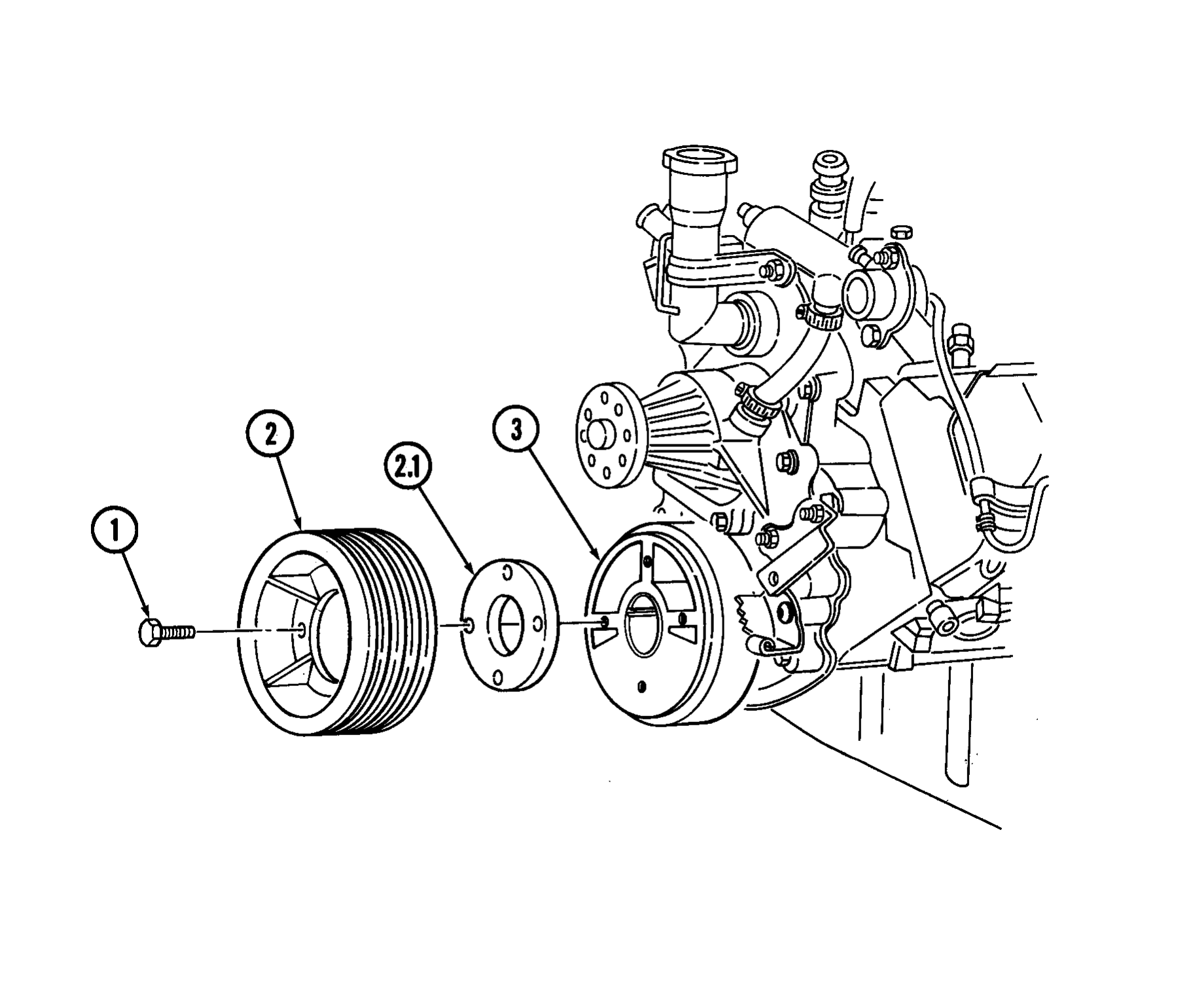
aa. Crankshaft Pulley
1. Apply sealing compound to four capscrews (1).
2. Install crankshaft pulley (2) and spacer (2.1) (if removed) on torsional damper (3) with four capscrews (1).
3. Hold flywheel stationary with pry bar and tighten capscrews (1) to 48 lb-ft (65 N•m).
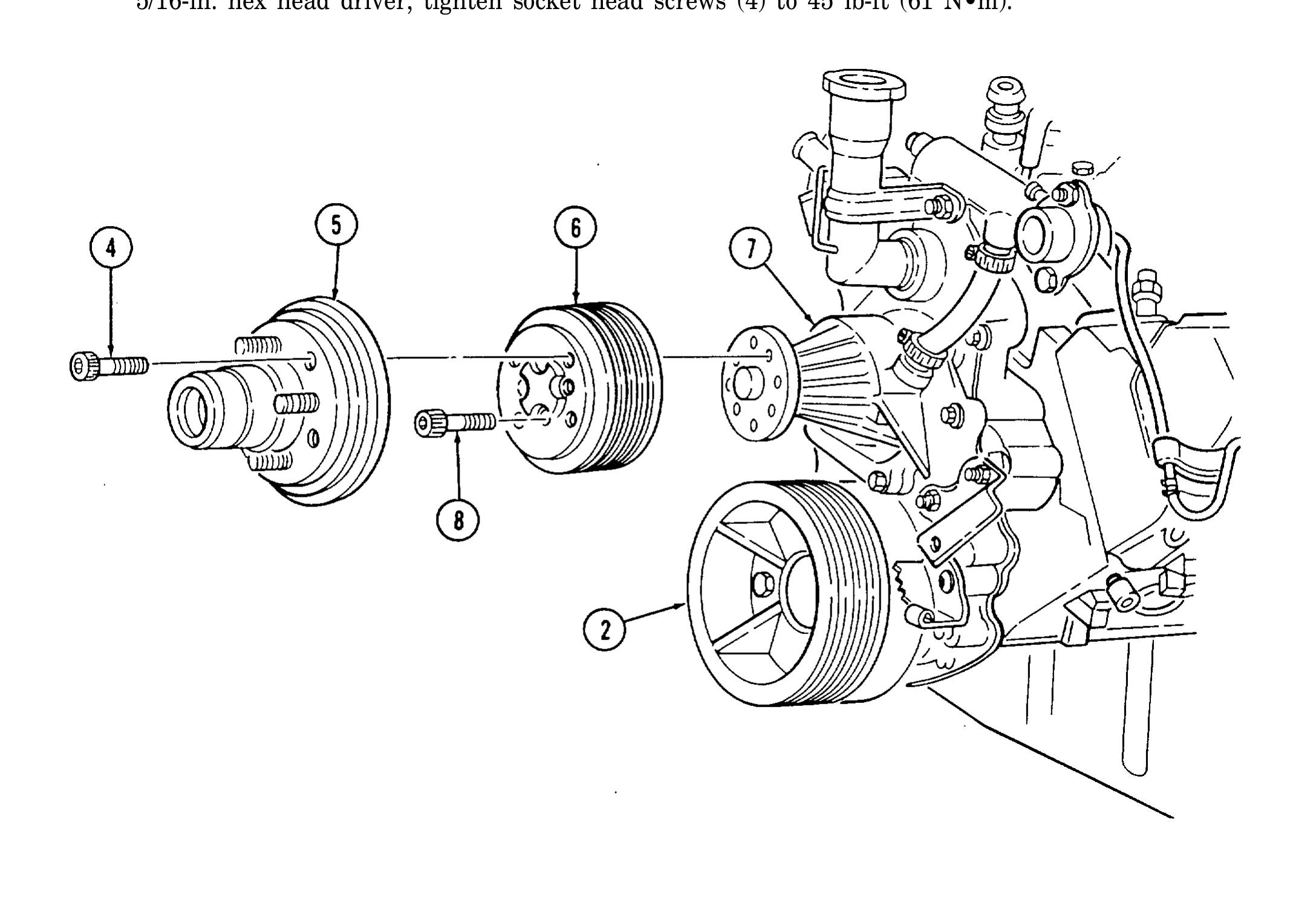
bb. Fan Drive and Water Pump Pulley
1. Apply sealing compound to four socket head screws (8).
2. Install water pump pulley (6) on water pump (7) with four socket head screws (8).
3. position pry bar between water pump pulley (6) and crankshaft pulley (2) and apply pressure t O prevent rotation. Using 6 mm hex head driver, tighten socket head screws (8) to 20 lb-ft (27 N•m).
4. Apply sealing compound to four socket head screws (4).
5. Install fan drive (5) on water pump pulley (6) with four socket head screws (4). Repeat step 3. Using 5/16-in. hex head driver, tighten socket head screws (4) to 45 lb-ft (61 N•m).
FOLLOW-ON TASKS: ● Remove engine from repair stand (para. 2-14). ● Perform engine run-in (para. 2-43).