2-15. Engine Disassembly Into Subassemblies
TM 9-2815-237-34 · Chapter 2 — Engine Maintenance
This task covers:
     a. Fan Drive and Water Pump Pulley               m.    Glow Plugs
     b. Crankshaft Pulley                             n.    Cylinder Heads
     c. Torsional Damper                              o.    Valve Lifters
     c.1. Wastegate Actuator                          p.    Water Pump and Adapter Plate
     c.2. Wastegate Housing                           q.    Fuel Injection Pump
     c.3. Manifold-to-Turbocharger Exhaust Pipe       r.    Timing Gear Cover
     c.4. Turbocharger                                s.    Timing Chain and Drive Sprockets
     d. Exhaust Manifolds                             t.    Oil Filter, Adapter, and Oil Pressure Sending Unit
     e. Intake Manifold                               u.    Oil Pan
     f. Water Crossover                               v.    Oil Pump
     g. Fuel Injection Lines                          w.    Fuel Pump
     h. Fuel Supply and Return Lines                  x.    Oil Pump Drive
     i. Modulator Link                                y.    Camshaft
     j. Rocker Arm Covers                             z.    Pistons and Connecting Rods
     k. Rocker Arm Shafts and Pushrods                aa.   Flywheel
     l. Fuel Injection Nozzles                        bb.   Crankshaft and Main Bearings

INITIAL SETUP:
   Tools                                              Personnel Required
     General mechanic’s tool kit:                       One mechanic
      automotive (Appendix E, Item 1)                   One assistant
     Puller (Appendix E, Item 19)                     Equipment Condition
     Cylinder ridge reamer (Appendix E, Item 11)
     Dial indicator (Appendix E, Item 10)               Engine mounted on repair stand (para. 2-14).
     Special Tools                                    General Safety Instructions
       Hydraulic valve lifter remover                   • Do not perform this procedure near fire, flame,
        (Appendix E, Item 4)                              or sparks.
       Injection nozzle socket (Appendix E, Item 5)     • Gaskets installed on some 6.2L engines
       Glow plug socket (Appendix E, Item 6)              assembled prior to 1991 may contain asbestos.
       Hex-head driver, 6 mm (Appendix E, Item 7)         Gaskets should be disposed of IAW current
       Hex-head driver, 8 mm (Appendix E, Item 8)         directives.
       Hex-head driver, 5/16-in.
        (Appendix E, Item 9)

                                                   NOT E
            • Work area should be clean, well-ventilated, and free from blowing dirt and dust.
            • In some cases, flanged head fasteners may be present instead of standard
              fasteners and washers. In all cases, washers should be used when replacing a
              flanged head fastener with a standard fastener.
            • Disassembly procedures for pre-1990, 1990 and above 6.2L and 6.5L engines are
              basically the same. Any differences in procedures are noted. Refer to para.
              1-10 to determine engine model before ordering replacement parts.

a. Fan Drive and Water Pump Pulley
                                                   NOT E
            It may be necessary to apply compressed air to fan drive fitting. This disengages
            fan drive and allows access to socket head capscrews.
 1.    Position pry bar between water pump pulley (3) and crankshaft pulley (6) and apply pressure.
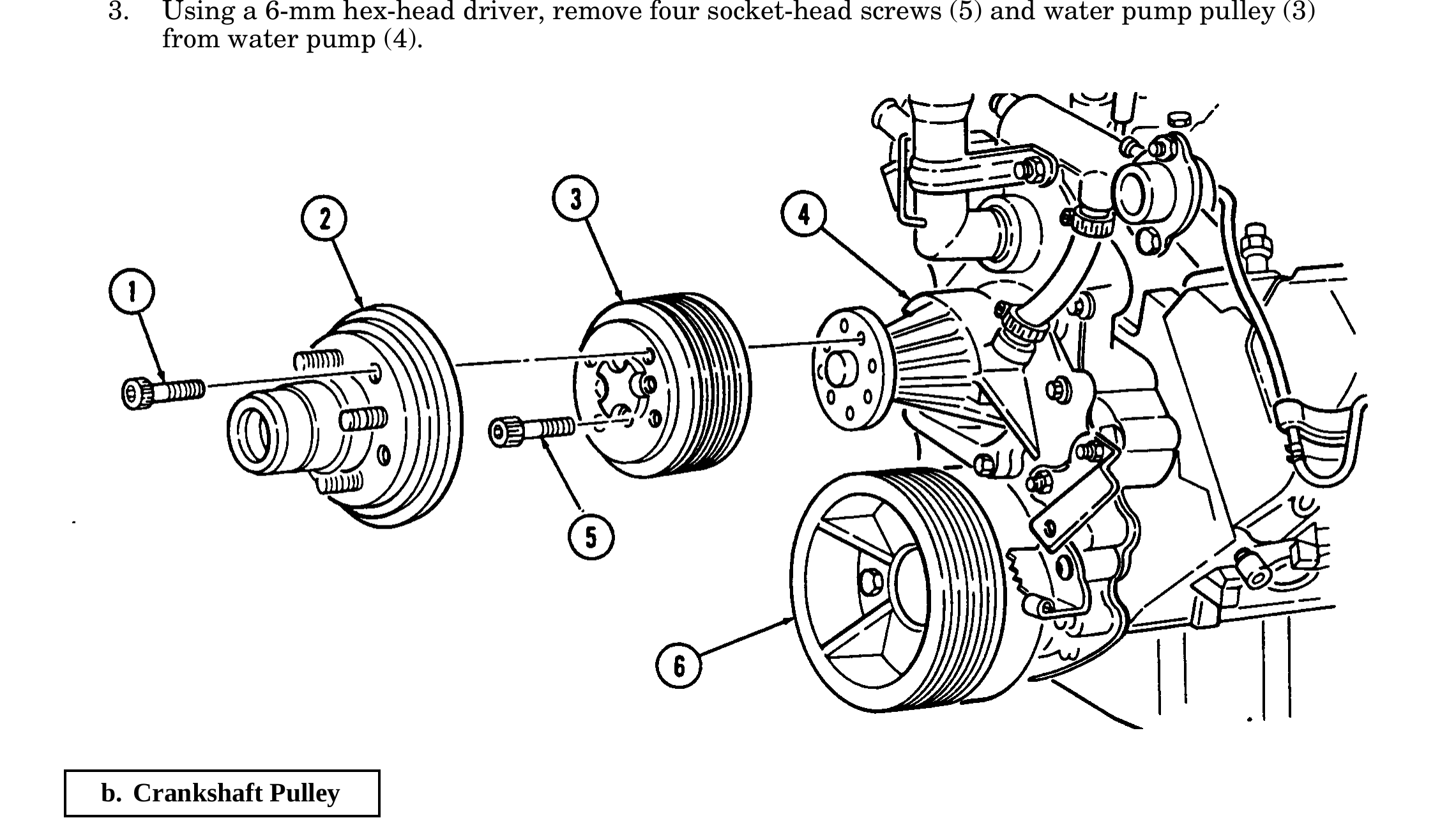
2. Using a 5/16-in. hex-head driver, remove four socket-head screws (1) and fan drive (2) from water pump pulley (3).
3. Using a 6-mm hex-head driver, remove four socket-head screws (5) and water pump pulley (3) from water pump (4).
b. Crankshaft Pulley
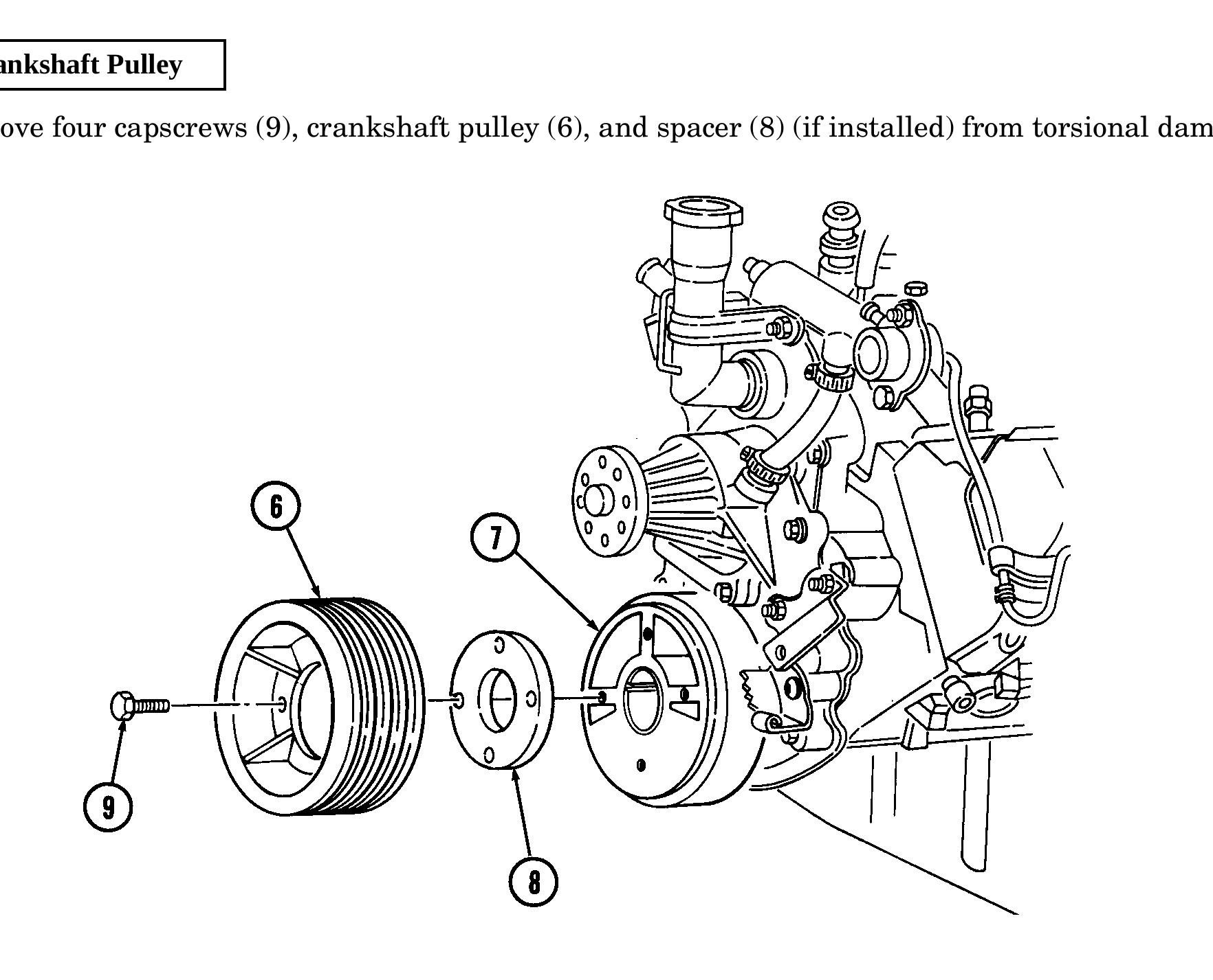
Remove four capscrews (9), crankshaft pulley (6), and spacer (8) (if installed) from torsional damper (7).
c. Torsional Damper
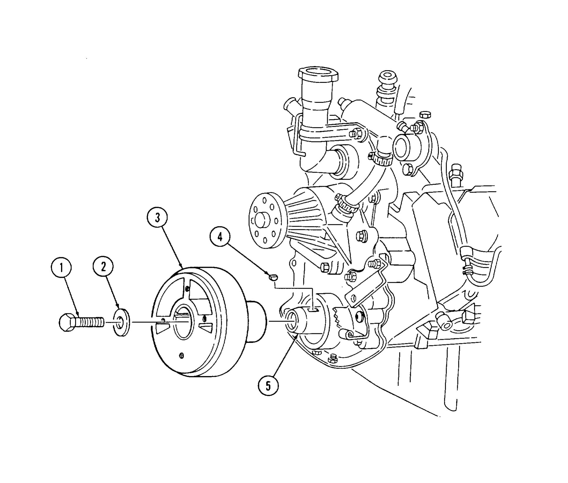
1. Hold flywheel stationary with pry bar.
2. Remove capscrew (1) and washer (2) from torsional damper (3) and crankshaft (5).
3. Reinstall capscrew (1) and remove torsional damper (3) with puller.
4. Remove capscrew (1) and woodruff key (4) from crankshaft (5). Discard woodruff key (4).
c.1. Wastegate Actuator
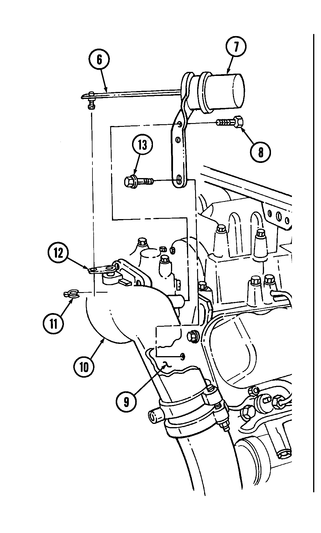
1. Remove clip (11) and actuator rod (6) from wastegate bellcrank (12).
2. Remove two capscrews (8) from wastegate actuator (7) and wastegate housing (10).
3. Remove capscrew (13) and wastegate actuator (7) from cylinder head (9).
c.2. Wastegate Housing
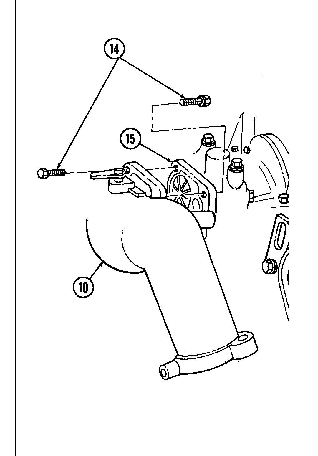
Remove four capscrews (14) and wastegate housing (10) from turbocharger (15).
c.3. Manifold-to-Turbocharger Exhaust Pipe
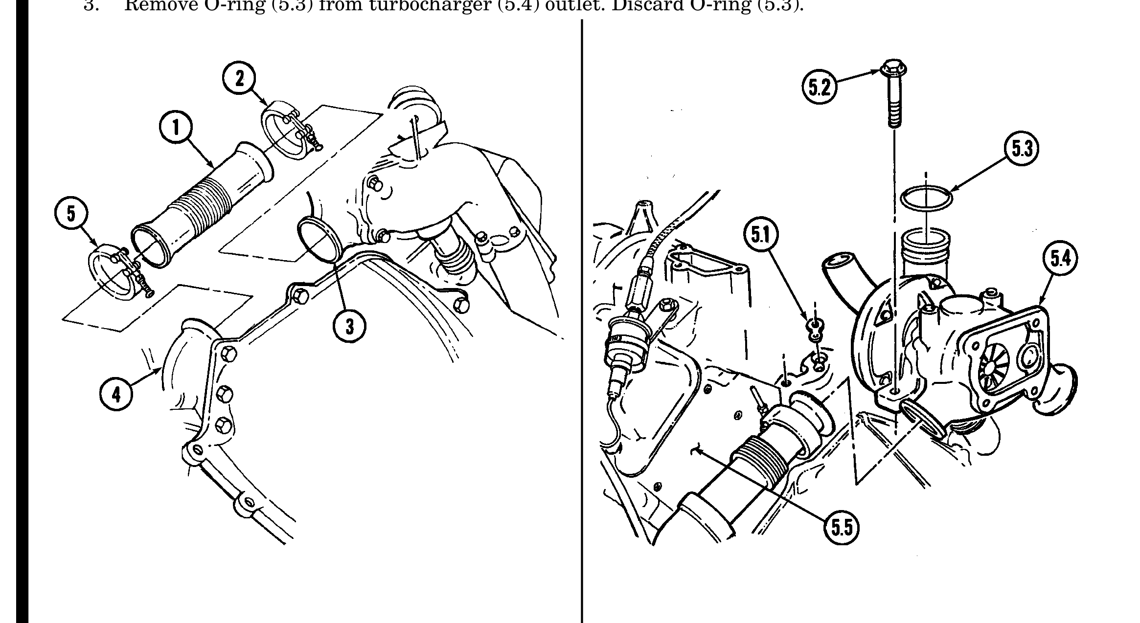
1. Loosen clamp (5) and remove exhaust pipe (1) from exhaust manifold (4). Slide clamp (5) onto exhaust pipe (1).
2. Loosen clamp (2) and remove exhaust pipe (1) from turbocharger (3). Slide clamp (2) onto exhaust pipe (1).
3. Remove clamps (2) and (5) from exhaust pipe (1).
4. Repeat steps 1 through 3 for opposite side of engine.
c.4. Turbocharger
1. Remove two capscrews (5.2) and turbocharger (5.4) from engine block (5.5).
2. Remove turbocharger oil gasket (5.1) from engine block (5.5). Discard gasket (5.1).
3. Remove O-ring (5.3) from turbocharger (5.4) outlet. Discard O-ring (5.3).
d. Exhaust Manifolds
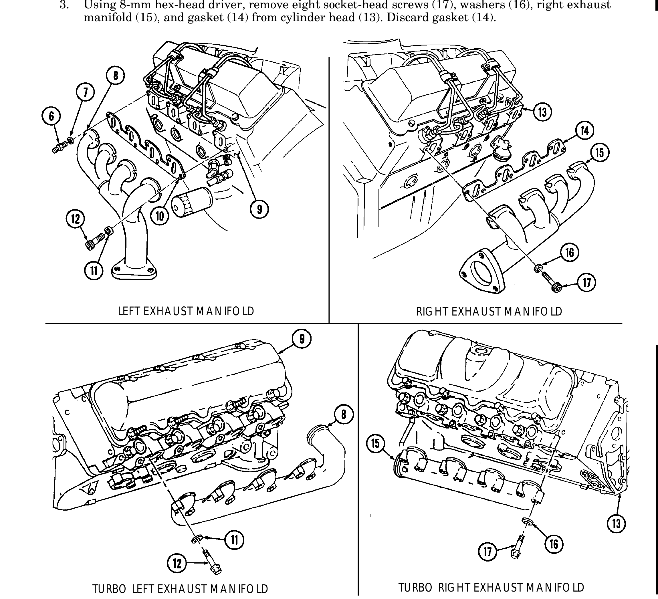
1. Remove stud (6) and washer (7) securing left exhaust manifold (8) to cylinder head (9).
2. Using 8-mm hex-head driver, remove seven socket-head screws (12), washers (11), left exhaust manifold (8), and gasket (10) from cylinder head (9). Discard gasket (10).
3. Using 8-mm hex-head driver, remove eight socket-head screws (17), washers (16), right exhaust manifold (15), and gasket (14) from cylinder head (13). Discard gasket (14).
LEFT EXHAUST MANIFOLD RIGHT EXHAUST MANIFOLD
TURBO LEFT EXHAUST MANIFOLD TURBO RIGHT EXHAUST MANIFOLD
e. Intake Manifold
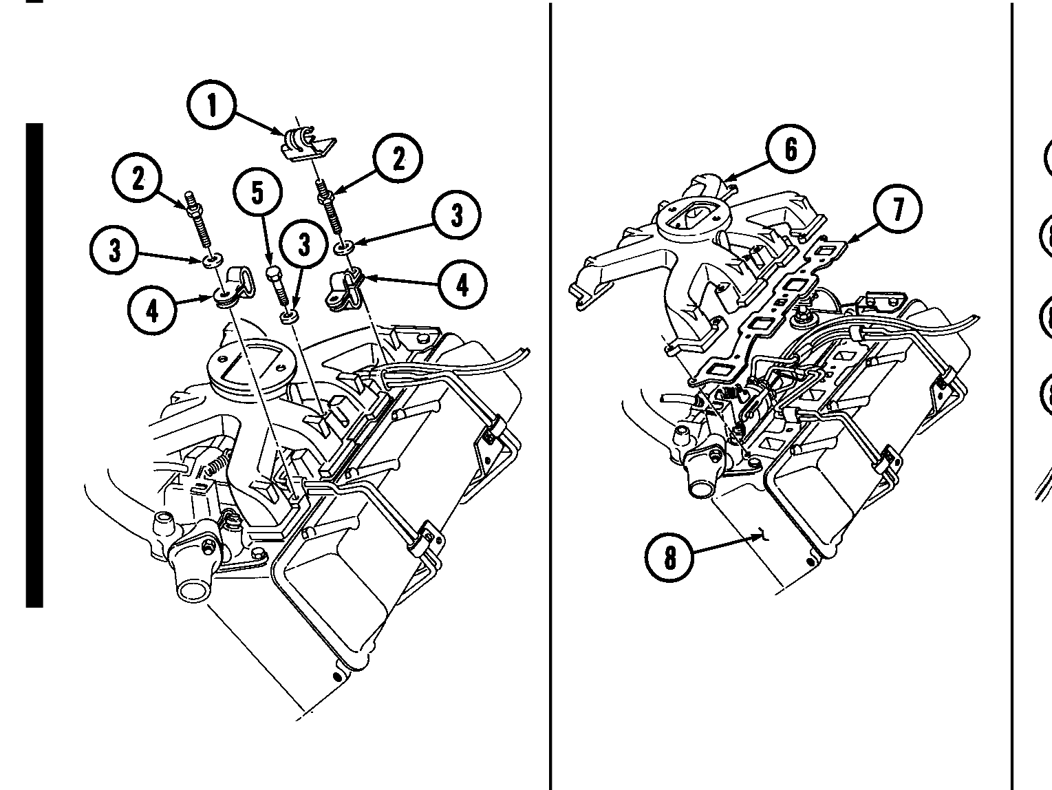
1. Remove fuel filter line clamp (1) from stud (2).
2. Remove six intake manifold capscrews (5), ten studs (2), and sixteen washers (3).
3. Remove four intake manifold capscrews (5), twelve studs (2), and sixteen washers (3).
4. Remove four injection line clips (4).
5. Remove intake manifold (6) and two gaskets (7) from cylinder heads (8). Discard gaskets (7).
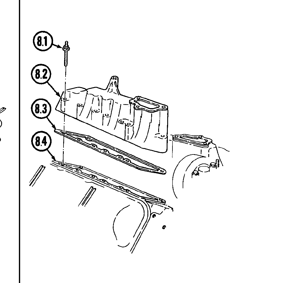
6. Remove eight intake manifold studs (8.1) from intake manifold (8.2). .WARNING. Gaskets installed on some 6.2L engines assembled prior to 1991 may contain asbestos. Gaskets should be removed with a scraper or putty knife and then be disposed of IAW current directives. Inhalation of asbestos fibers can cause respiratory ailments.
7. Remove intake manifold (8.2) and gasket (8.3) from cylinder head (8.4). Discard gasket (8.3).
8. Repeat steps 6 and 7 for opposite side.
f. Water Crossover
1. Remove four capscrews (9) securing water crossover (14) to cylinder heads (8).
2. Loosen hose clamp (12) and disconnect thermostat bypass hose (11) from water crossover nipple (13). .WARNING. Gaskets installed on some 6.2L engines assembled prior to 1991 may contain asbestos. Gaskets should be removed with a scraper or putty knife and then be disposed of IAW current directives. Inhalation of asbestos fibers can cause respiratory ailments.
3. Remove water crossover (14) and two gaskets (10). Discard gaskets (10).
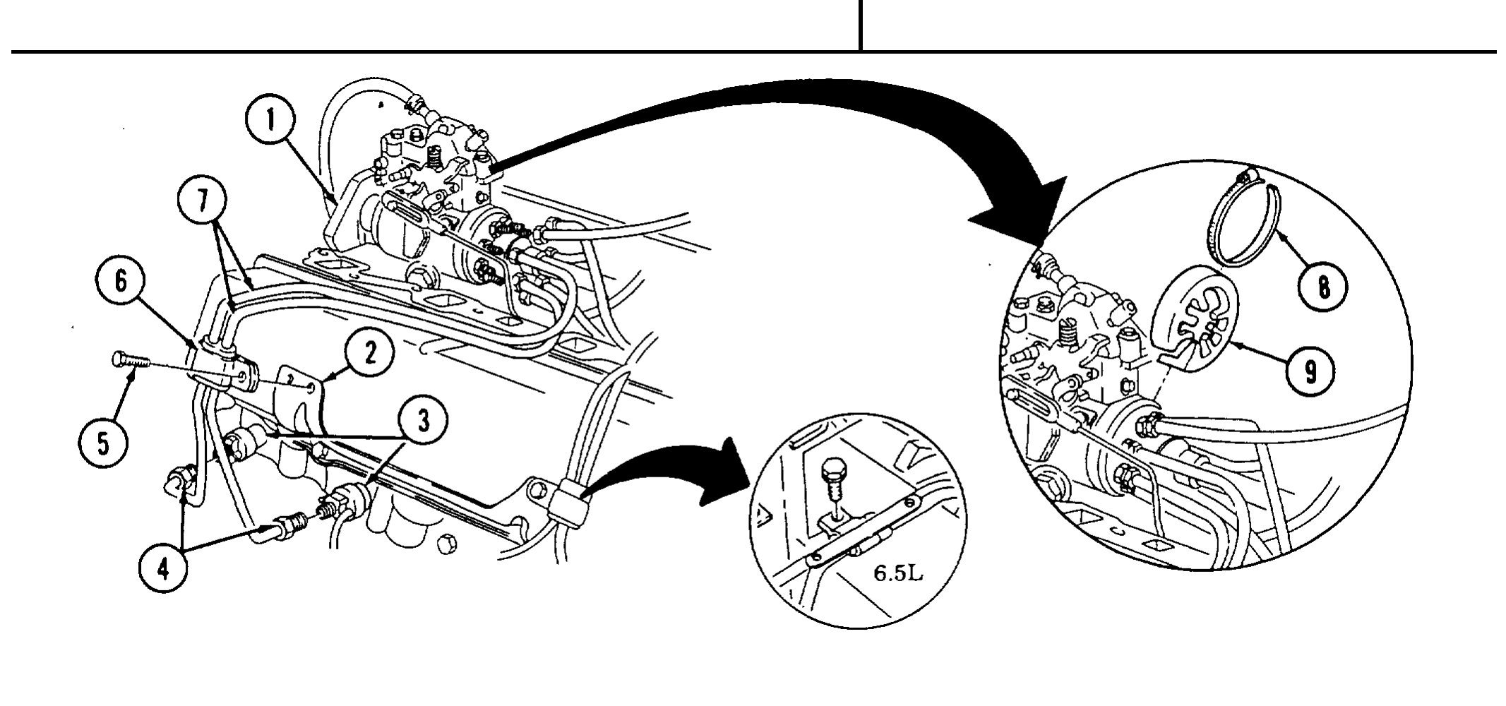
g. Fuel Injection Lines
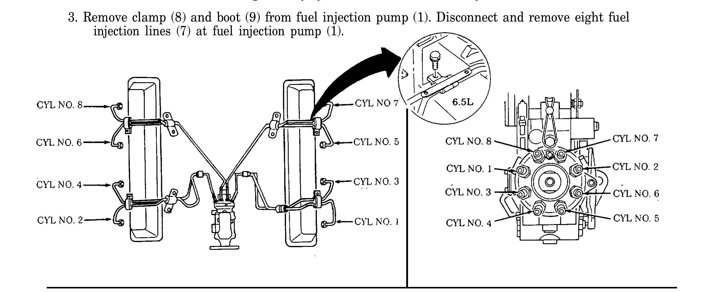
1. Loosen and disconnect eight fuel injection line nuts (4) at injection nozzles (3).
2. Remove four screw-assembled washers (5) and clamps (6) from support brackets (2).
3. Remove clamp (8) and boot (9) from fuel injection pump (1). Disconnect and remove eight fuel injection lines (7) at fuel injection pump (1).
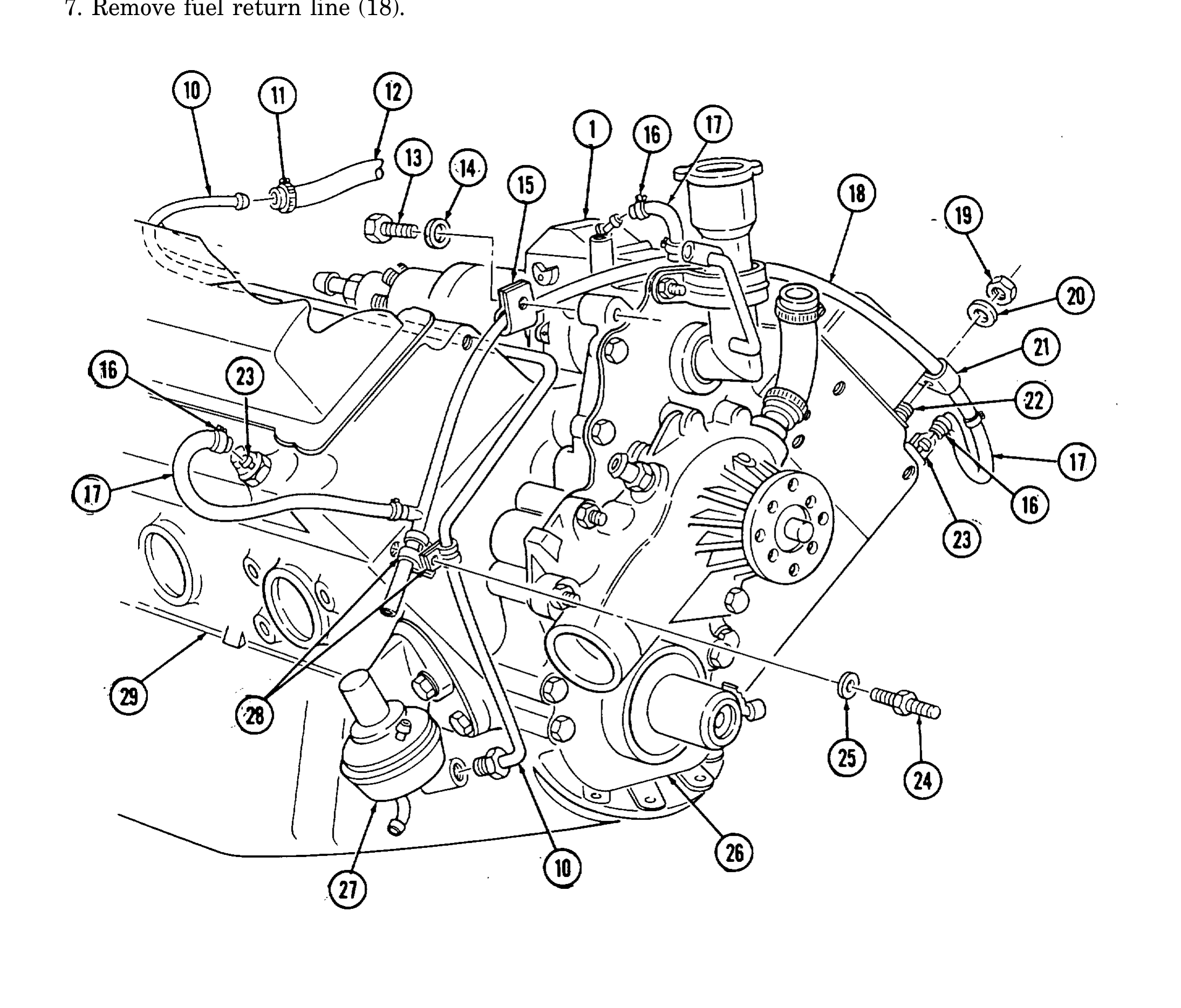
h. Fuel Supply and Return Lines
1. Loosen clamp (11) and remove fuel filter inlet hose (12) from fuel supplY line (10).
2. Disconnect fuel supply line (10) at fuel pump (27).
3. Remove stud (24), washer (25), two clamps (28) and fuel supply line (10) from fuel return line (18) and cylinder block (29).
4. Remove nut (19), washer (20), and clamp (21) from fuel return line (18) and rocker arm cover stud (22).
5. Remove capscrew (13), washer (14), and clamp (15) from fuel return line (18) and timing gear cover (26).
6. Loosen three clamps (16) and disconnect three hoses (17) at fuel injection pump (1) and front fuel injection nozzles (23).
7. Remove fuel return line (18).
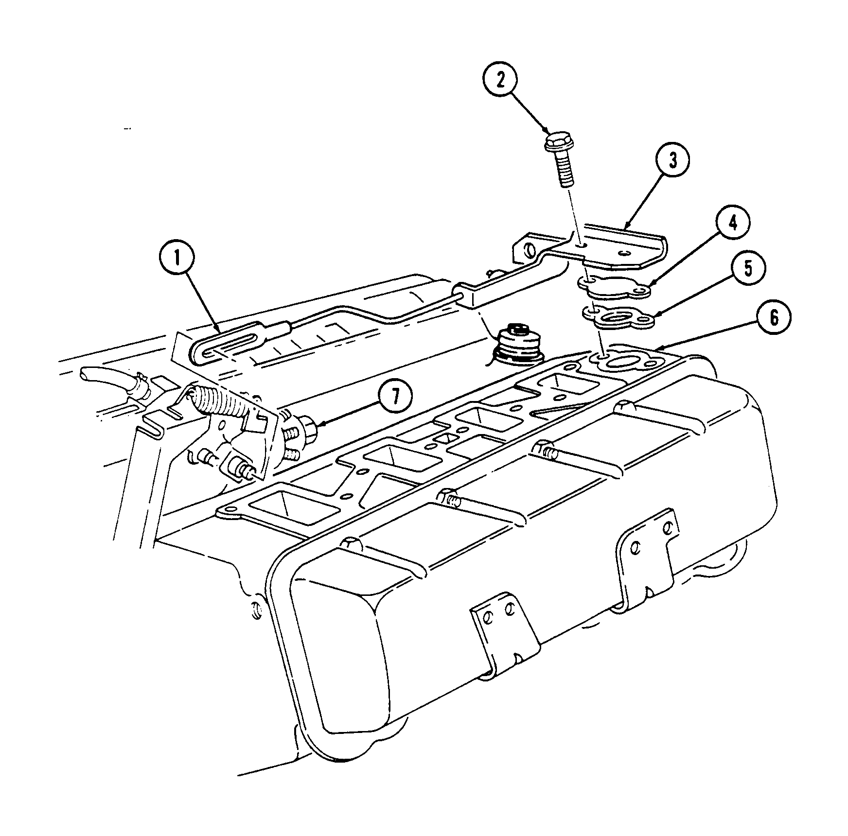
i. Modulator Link
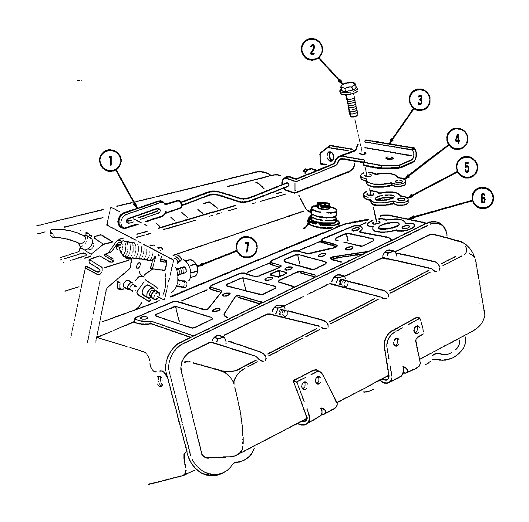
1. Remove two capscrews (2) securing modulator link bracket (3) to cylinder head (6). .WARNING. Gaskets installed on some 6.2L engines assembled prior to 1991 may contain asbestos. Gaskets should be removed with a scraper or putty knife and then be disposed of IAW current directives. Inhalation of asbestos fibers can cause respiratory ailments.
2. Slide modulator link (1) forward and disconnect from fuel injection pump (7) and remove bracket (3), modulator link (1), water jacket cover (4), and gasket (5). Discard gasket (5).
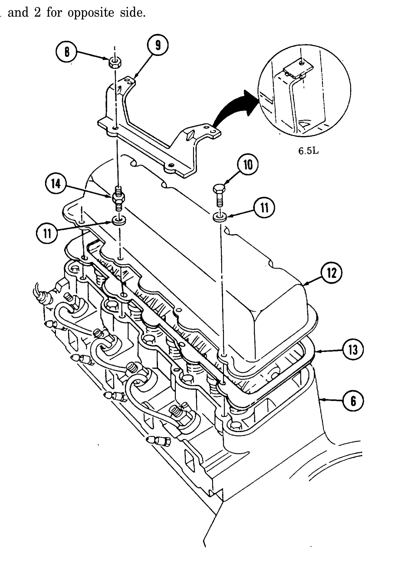
j. Rocker Arm Covers
1. Remove two nuts (8) and injection line support bracket (9) from rocker arm cover studs (14).
2. Remove a combination of three capscrews (10), five studs (14), eight washers (11), rocker arm cover (12), and gasket (13) (if applicable) from cylinder head (6).
3. Repeat steps 1 and 2 for opposite side.
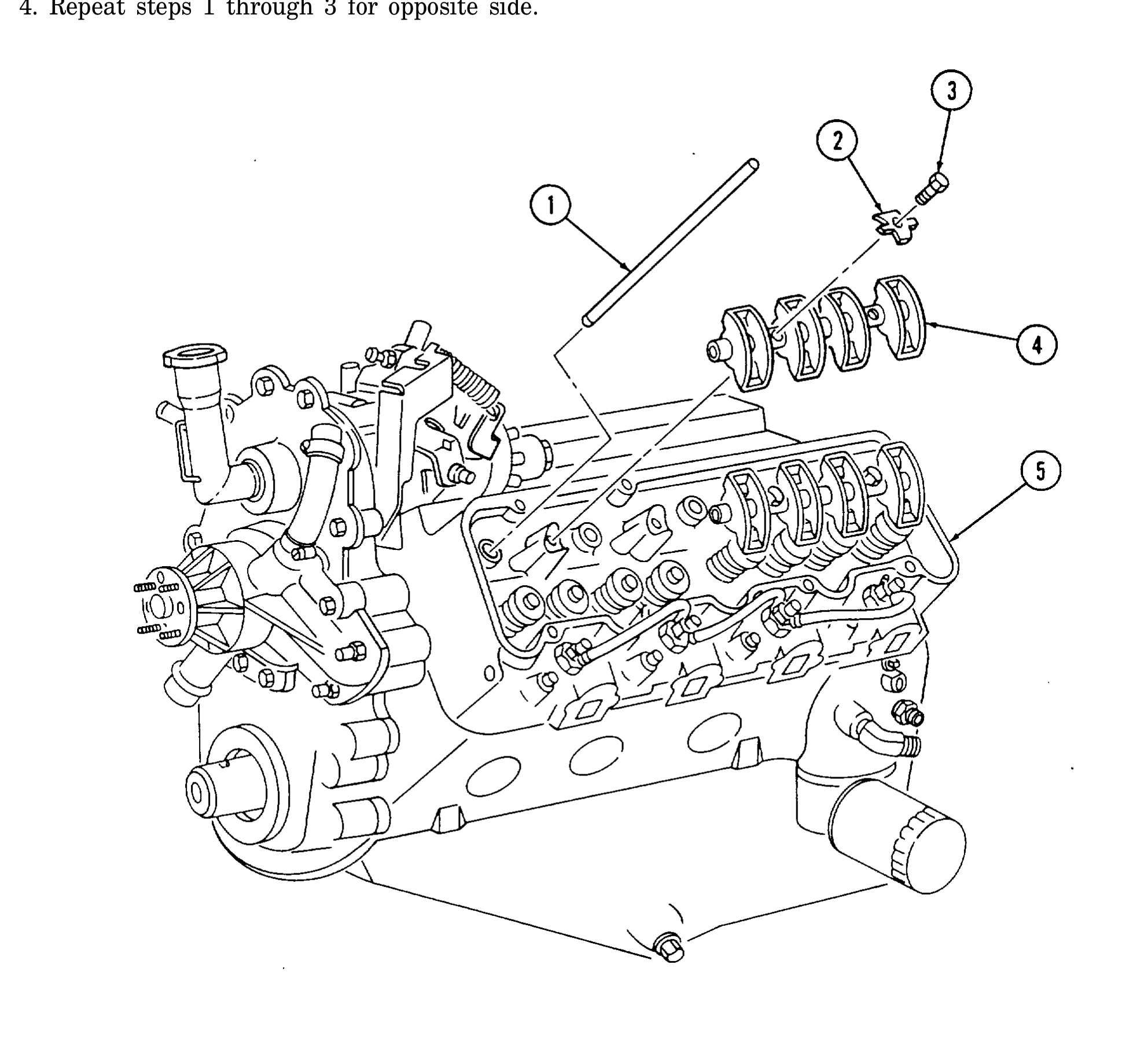
k. Rocker Arm Shafts and Pushrods
1. Remove four capscrews (3) and four retainers (2) from rocker arm and shaft assembly (4) and cylinder head (5).
2. Remove two rocker arm and shaft assemblies (4).
3. Remove eight pushrods (1).
4. Repeat steps 1 through 3 for opposite side.
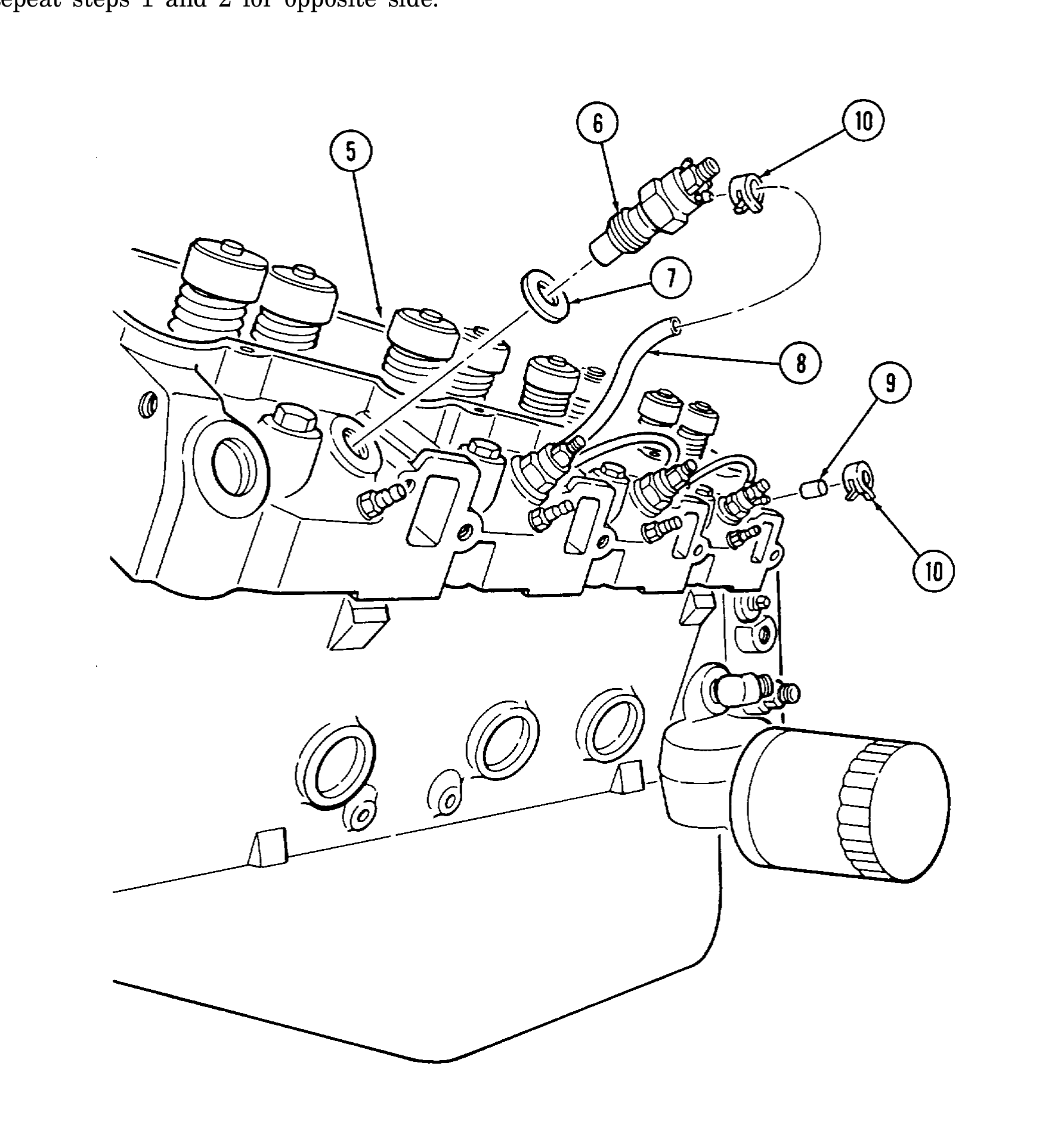
l. Fuel Injection Nozzles
1. Remove seven clamps (10), one cap (9), and three hoses (8) from fuel injection nozzles (6).
2. Using injection nozzle socket, remove four fuel injection nozzles (6) and gaskets (7) from cylinder head (5). Discard gaskets (7).
3. Repeat steps 1 and 2 for opposite side.
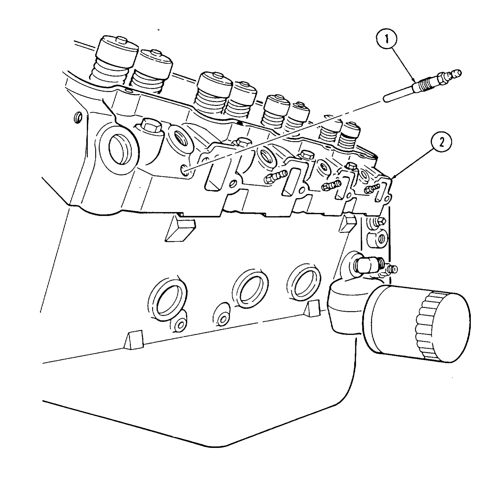
m. Glow Plugs
1. Using glow plug socket, remove four glow plugs (1) from cylinder head (2).
2. Repeat step 1 for opposite side.
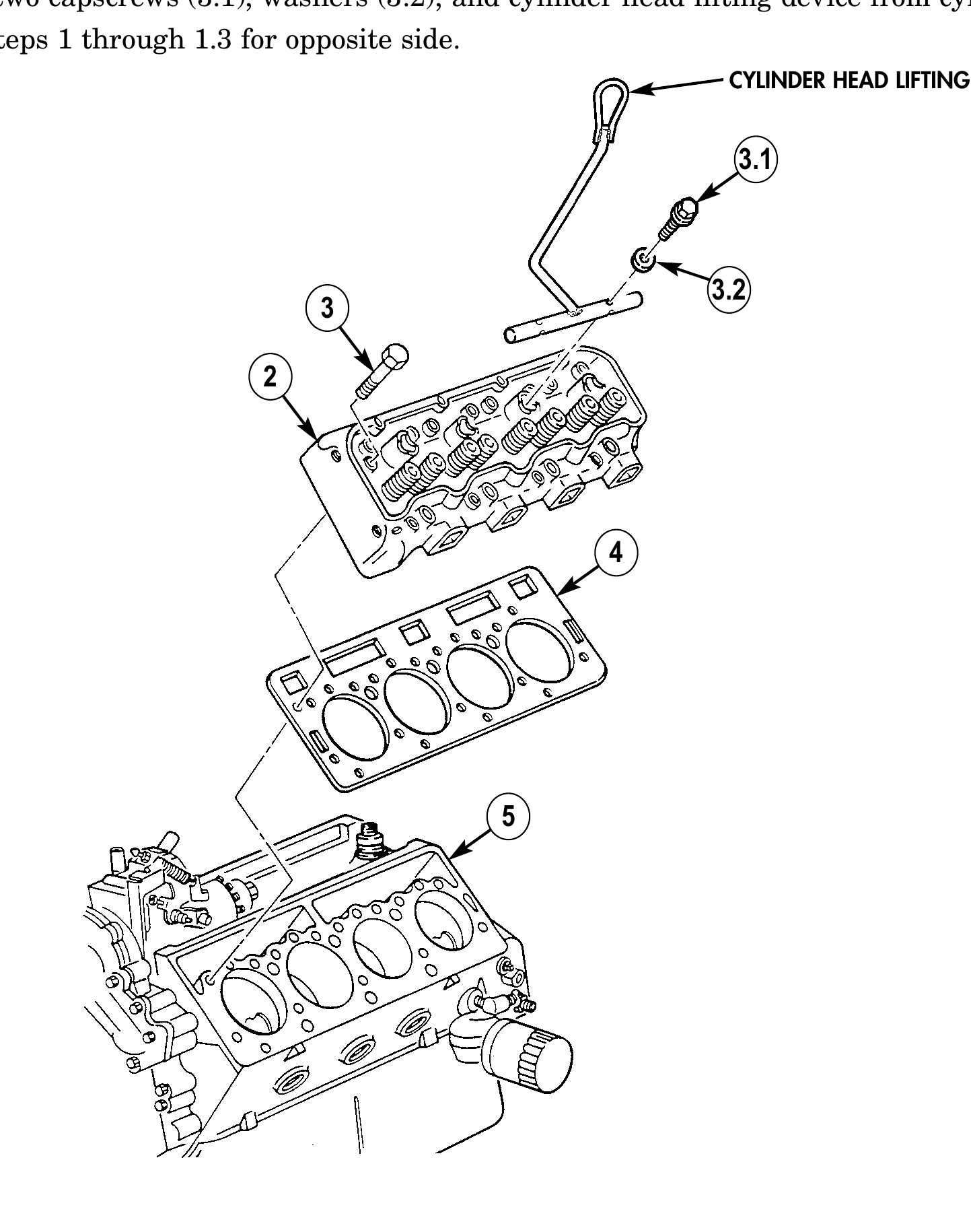
n. Cylinder Heads
.WARNING . Gaskets installed on some 6.2L engines assembled prior to 1991 may contain asbestos. Gaskets should be removed with a scraper or putty knife and then be disposed of IAW current directives. Inhalation of asbestos fibers can cause respiratory ailments.
1. Remove seventeen capscrews (3) from cylinder head (2) and cylinder block (5).
1.1. Install cylinder head lifting device on center of cylinder head (2) with two washers (3.2) and capscrews (3.1).
1.2. Using a hoist or other lifting device, remove cylinder head (2) and cylinder head gasket (4) from cylinder block (5).
1.3. Remove two capscrews (3.1), washers (3.2), and cylinder head lifting device from cylinder head (2).
2. Repeat steps 1 through 1.3 for opposite side. CYLINDER HEAD LIFTING DEVICE
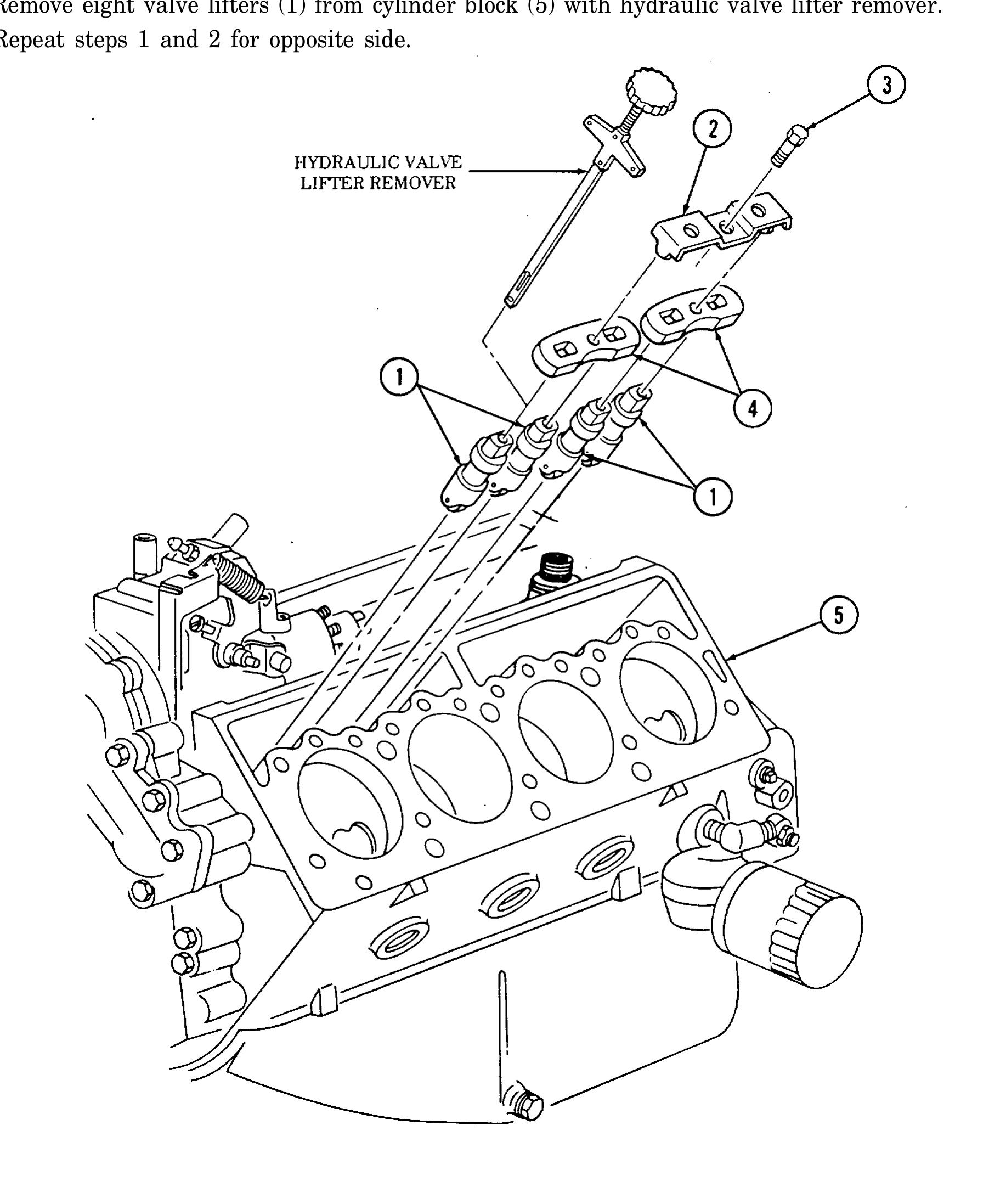
o. Valve Lifters
1. Remove two capscrews (3), guide plate clamps (2), and four guide plates (4) from cylinder block (5).
2. Remove eight valve lifters (1) from cylinder block (5) with hydraulic valve lifter remover.
3. Repeat steps 1 and 2 for opposite side.
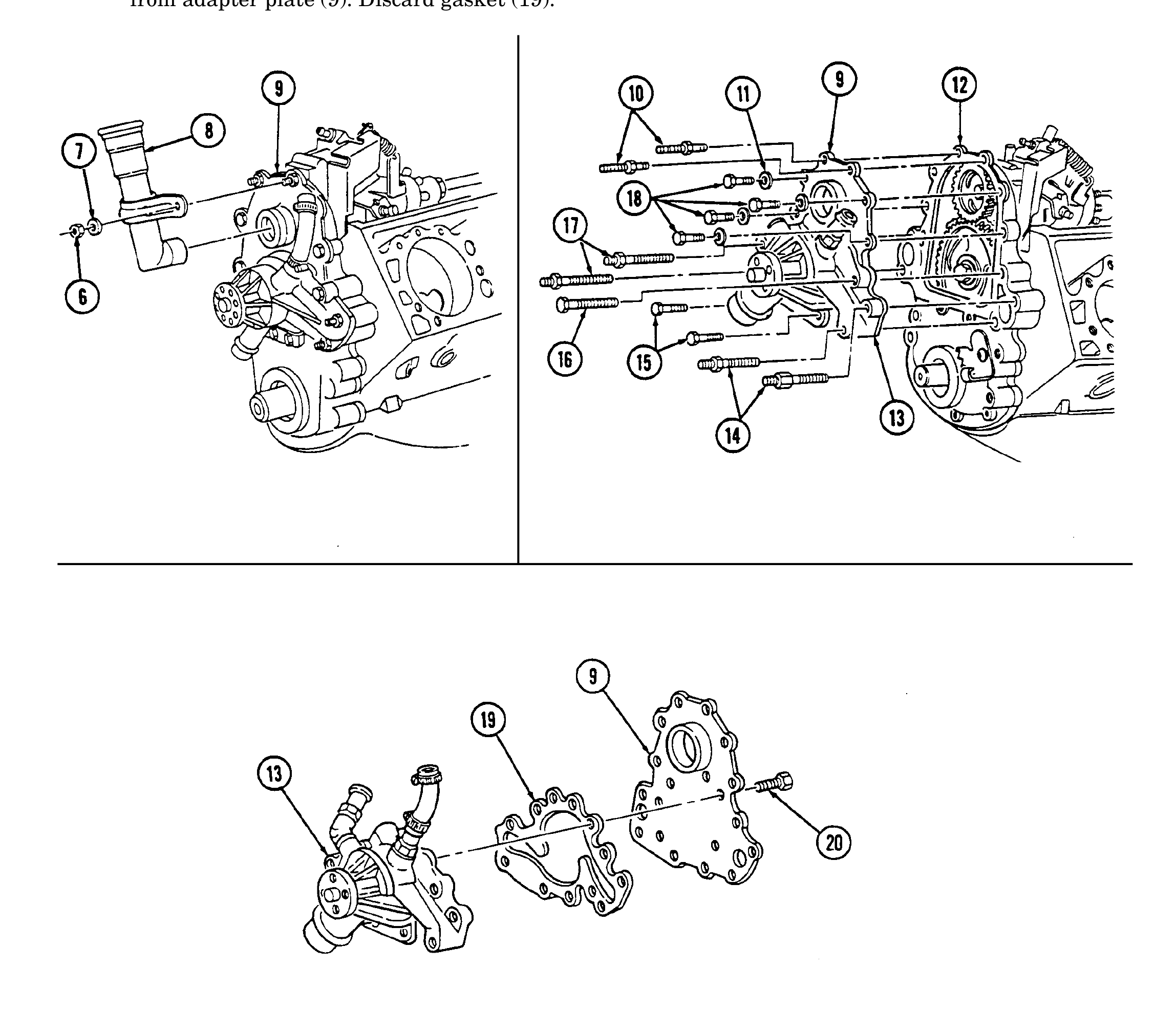
p. Water Pump and Adapter Plate
1. Remove two nuts (6), washers (7), and oil fill tube (8) from adapter plate (9).
2. Remove two studs (10), (14), and (17), four capscrews (18), washers (11), two capscrews (15), capscrew (16), water pump (13), and adapter plate (9) from timing gear cover (12). .WARNING. Gaskets installed on some 6.2L engines assembled prior to 1991 may contain asbestos. Gaskets should be removed with a scraper or putty knife and then be disposed of IAW current directives. Inhalation of asbestos fibers can cause respiratory ailments.
3. Remove seven capscrews (20) from water pump (13) and separate water pump (13) and gasket (19) from adapter plate (9). Discard gasket (19).
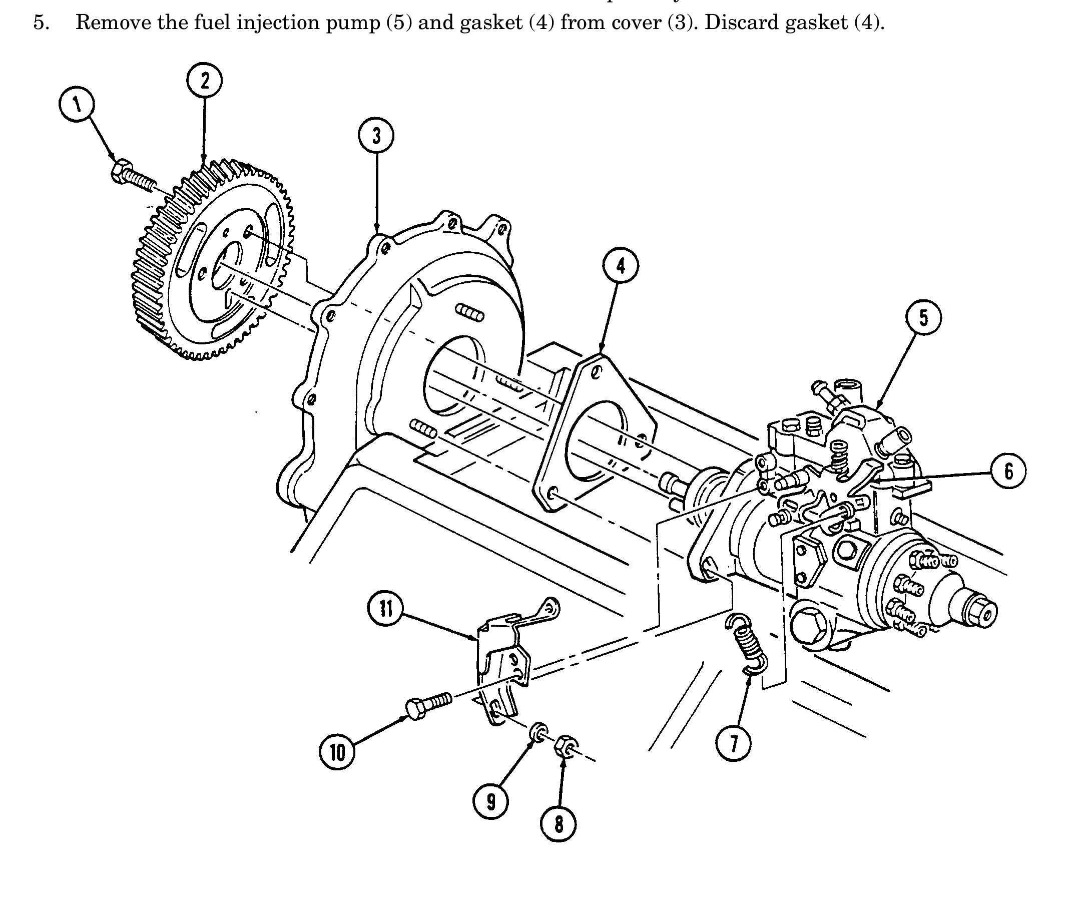
q. Fuel Injection Pump
1. Remove three capscrews (1) and pump driven gear (2) from fuel injection pump (5).
2. Remove idle return spring (7) from throttle lever (6).
3. Remove three nuts (8) and washers (9) from fuel injection pump (5) and timing gear cover (3).
4. Remove two capscrews (10) and accelerator cable bracket (11) from fuel injection pump (5). .WARNING. Gaskets installed on some 6.2L engines assembled prior to 1991 may contain asbestos. Gaskets should be removed with a scraper or putty knife and then be disposed of IAW current directives. Inhalation of asbestos fibers can cause respiratory ailments.
5. Remove the fuel injection pump (5) and gasket (4) from cover (3). Discard gasket (4).
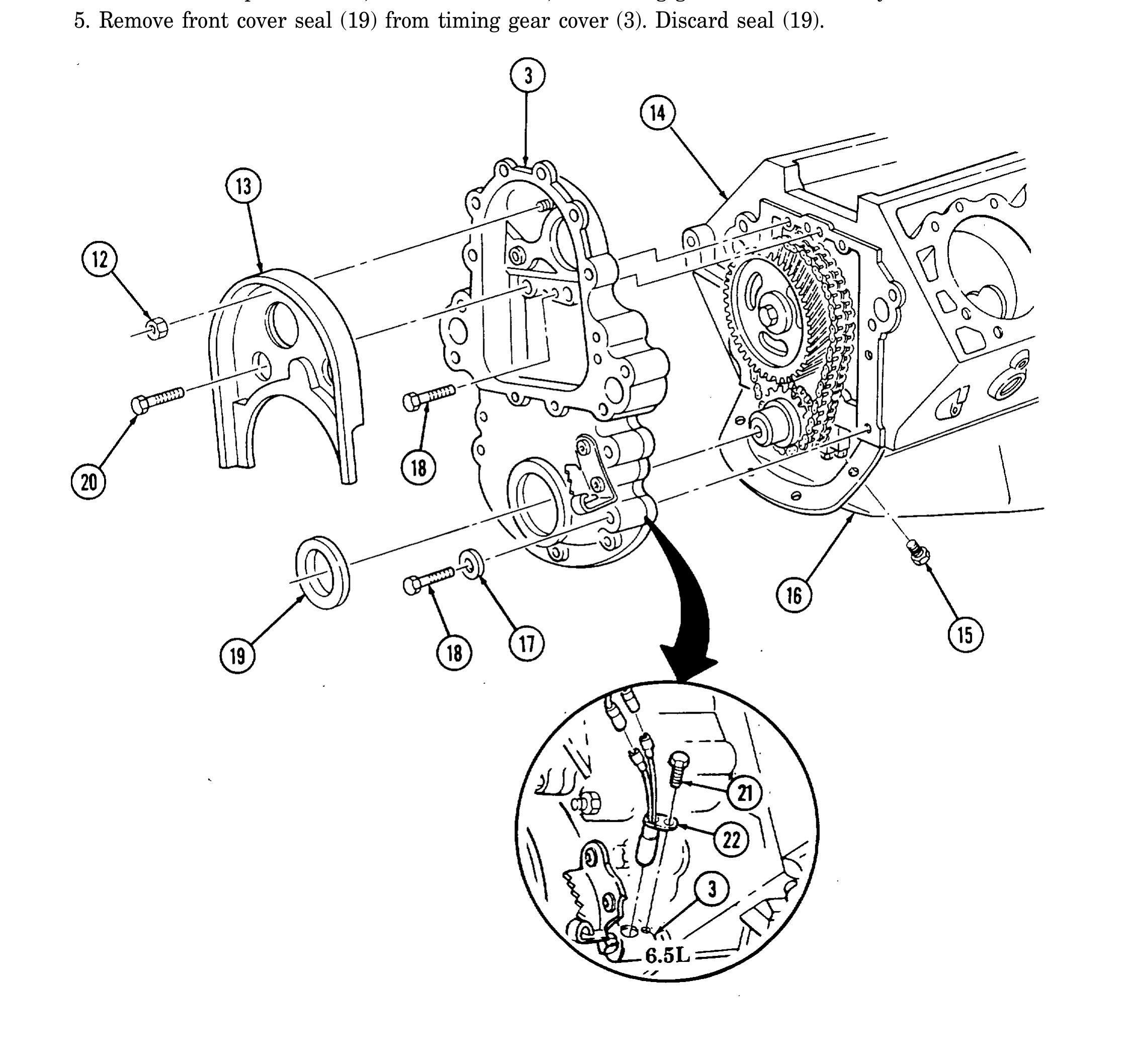
r. Timing Gear Cover
1. Remove capscrew (21) and rpm sensor (22) from timing gear cover (3).
2. Remove two capscrews (20), nut (12), and baffle (13) from timing gear cover (3).
3. Remove four capscrews (15) from oil pan (16) and timing gear cover (3).
4. Remove five capscrews (18), four washers (17), and timing gear cover (3) from cylinder block (14).
5. Remove front cover seal (19) from timing gear cover (3). Discard seal (19).
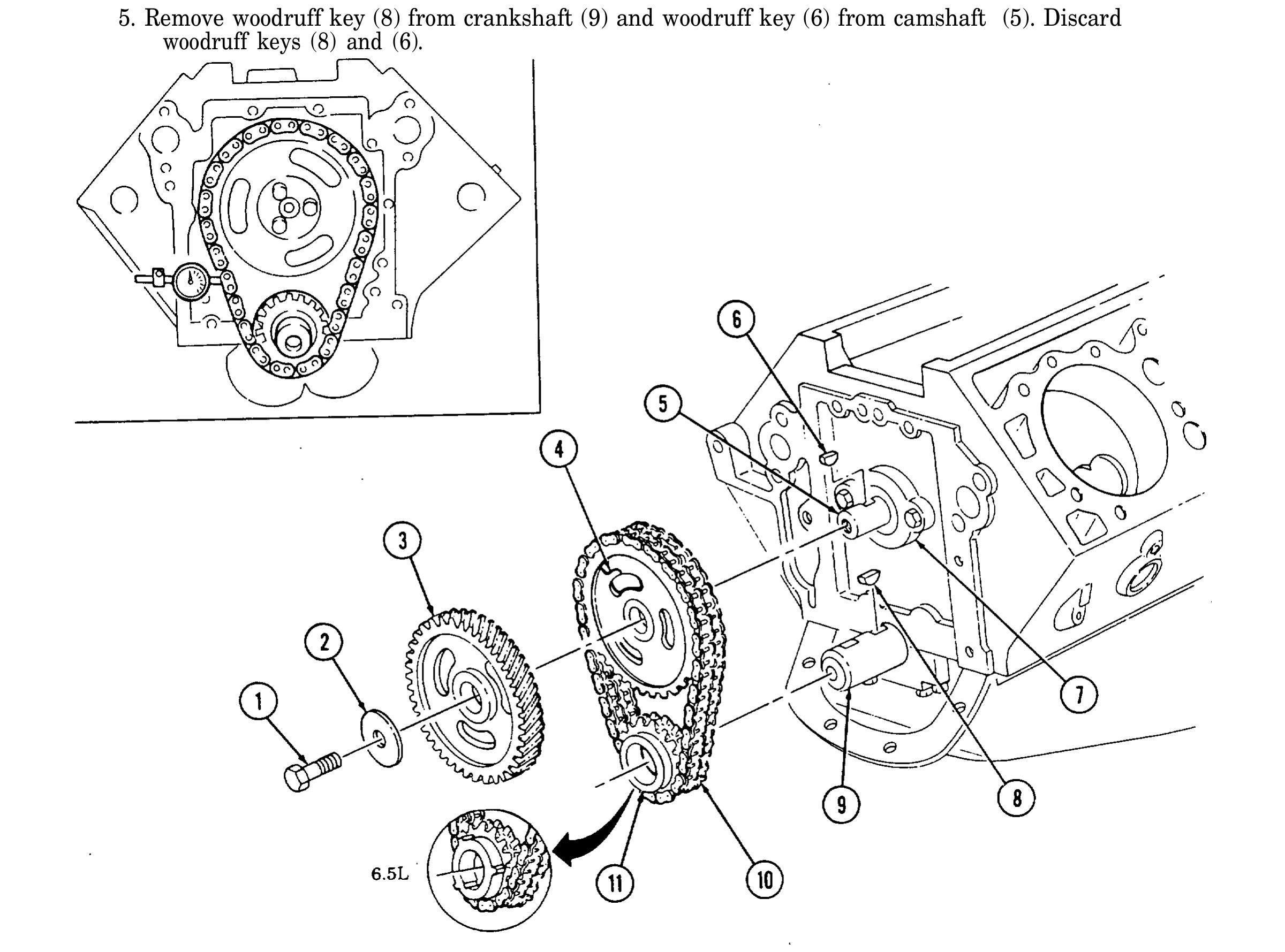
s. Timing Chain and Drive Sprockets
1. Using dial indicator, check timing chain (10) deflection midway between camshaft sprocket (4) and crankshaft sprocket (11). Total deflection must not exceed 0.810-in. (20.6 mm). If deflection exceeds specification, timing chain (10) must be replaced.
2. Using dial indicator, check camshaft end play. Camshaft end play must not be more than 0.012-in. (0.3 mm). If end play exceeds specification, camshaft sprocket (4), thrust plate (7), and spacer must be inspected for wear after removal.
3. Remove capscrew (1), washer (2), and pump drive gear (3) from camshaft (5).
4. Remove crankshaft sprocket (11), camshaft sprocket (4), and timing chain (10) as an assembly.
5. Remove woodruff key (8) from crankshaft (9) and woodruff key (6) from camshaft (5). Discard woodruff keys (8) and (6).
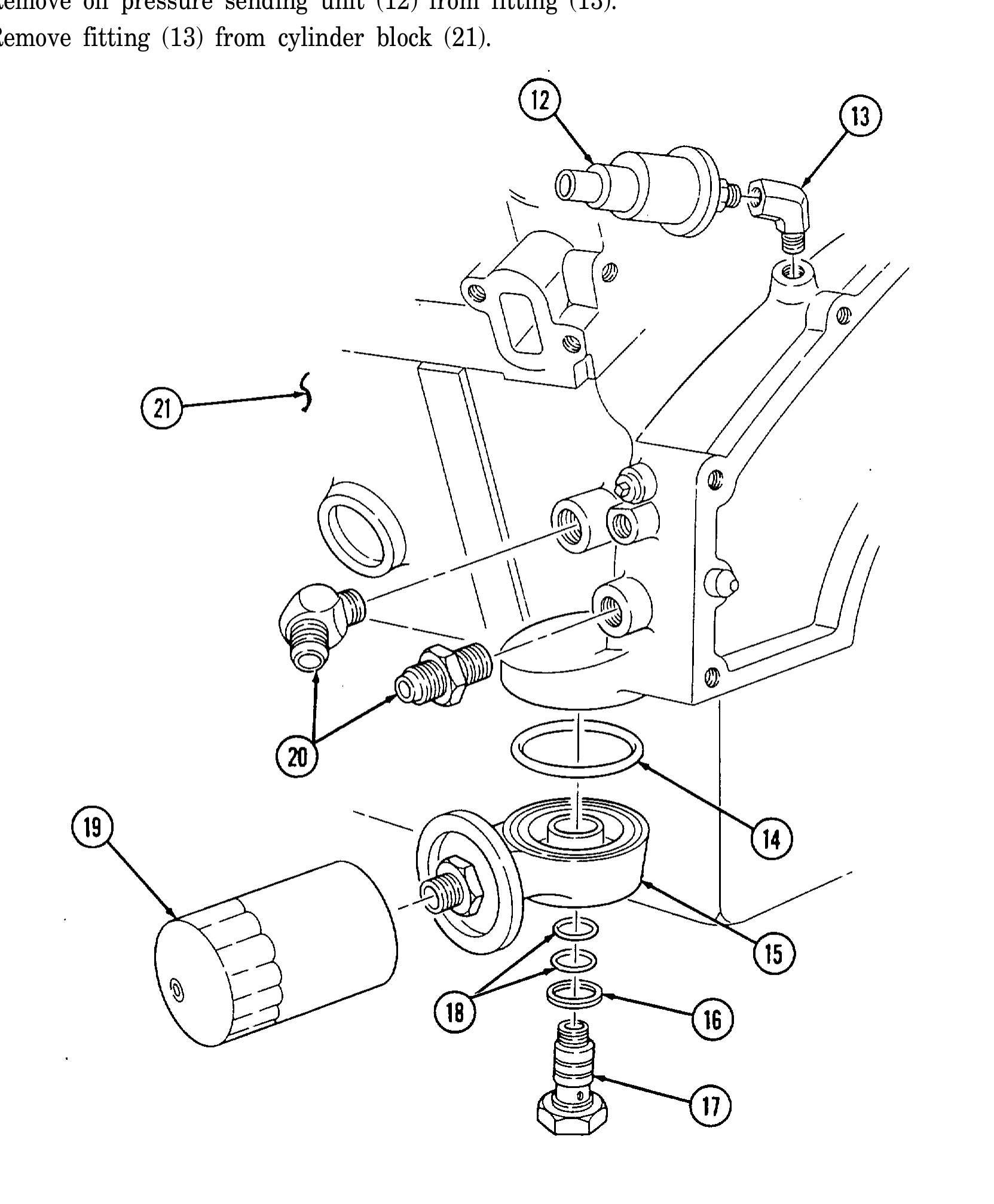
t. Oil Filter, Adaptter, and Oil Pressure Sending Unit
1. Remove oil filter (19) from adapter (15). Discard oil filter (19).
2. Remove adapter bolt (17), gasket (16), and adapter (15) from cylinder block (21). Discard gasket (16).
3. Remove two O-rings (18) from adapter bolt (17). Discard o-rings (18).
4. Remove O-ring (14) from adapter (15). Discard O-ring (14).
5. Remove two oil cooler line fittings (20) from cylinder block (21).
6. Remove oil pressure sending unit (12) from fitting (13).
7. Remove fitting (13) from cylinder block (21).
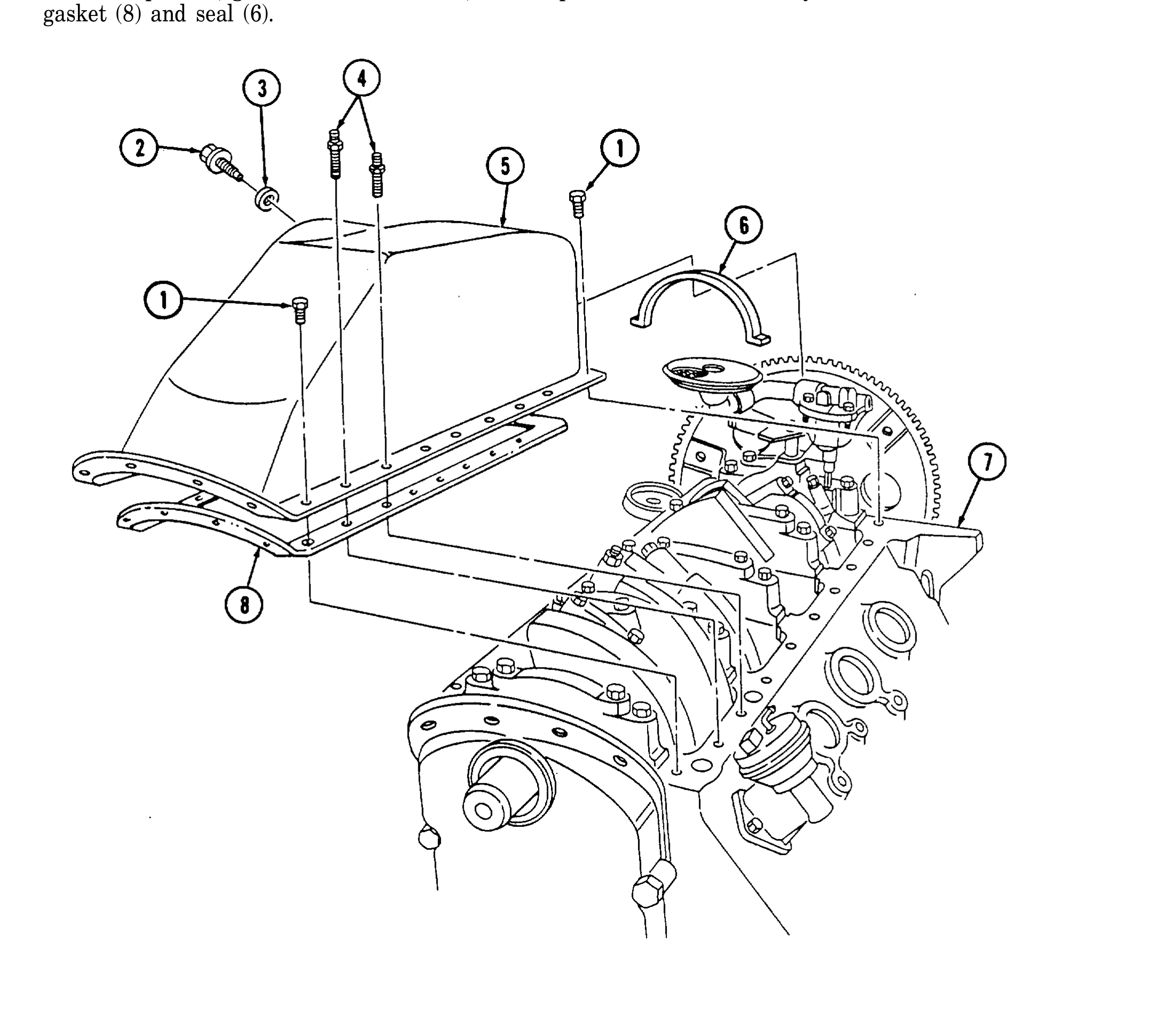
u. Oil Pan
1. Remove oil drainplug (2) and gasket (3) from oil pan (5) and drain oil. Inspect gasket (3) and discard if damaged.
2. Rotate cylinder block (7) 180°.
3. Remove eighteen capscrews (i) and two studs (4) from oil pan (5) and cylinder block (7).
4. Remove oil pan (5), gasket (8) (if installed), and oil pan rear seal (6) from cylinder block (7). Discard gasket (8) and seal (6).
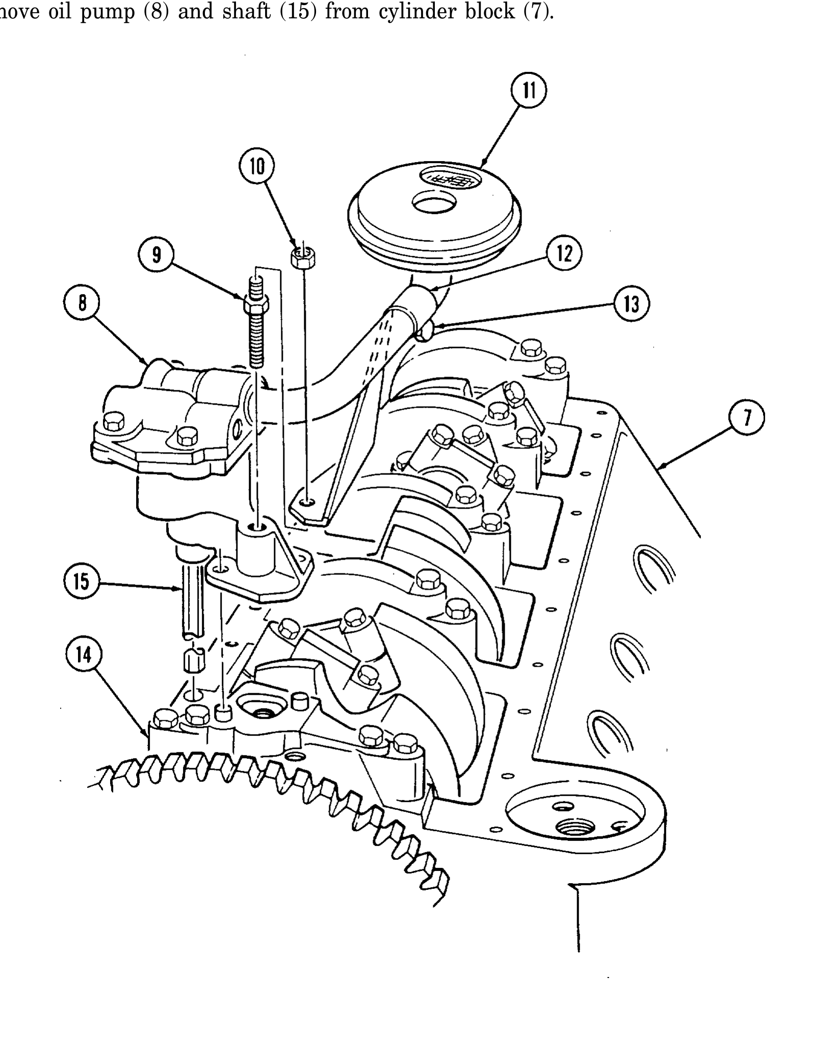
v. Oil Pump
1. Remove nut (10) securing bracket (12) to stud (9).
2. Loossencapscrew (13) from bracket (12) and oil screen (11) and slide bracket (12) off stud (9).
3. Remove stud (9) from oil pump (8) and rear main bearing cap (14).
4. Remove oil pump (8) and shaft (15) from cylinder block (7).
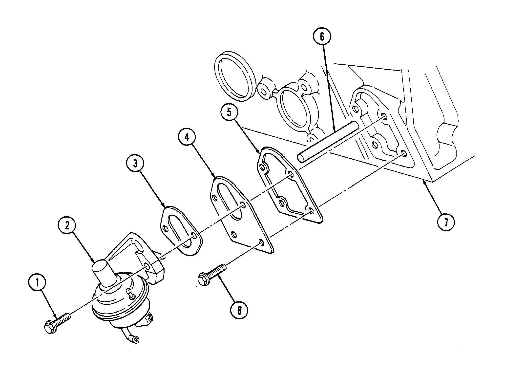
w. Fuel Pump
1. Rotate cylinder block (7) 180°. WARNING. Gaskets installed on some 6.2L engines assembled prior to 1991 may contain asbestos. Gaskets in steps 2 and 3 should be removed with a scraper or putty knife and then be disposed of IAW current directives. Inhalation of asbestos fibers can cause respiratory ailments.
2. Remove two capscrews (1), fuel pump (2), and gasket (3) from cylinder block (7). Discard gasket (3).
3. Remove two capscrews (8), adapter plate (4), gasket (5), and pushrod (6) from cylinder block (7). Discard gasket (5).
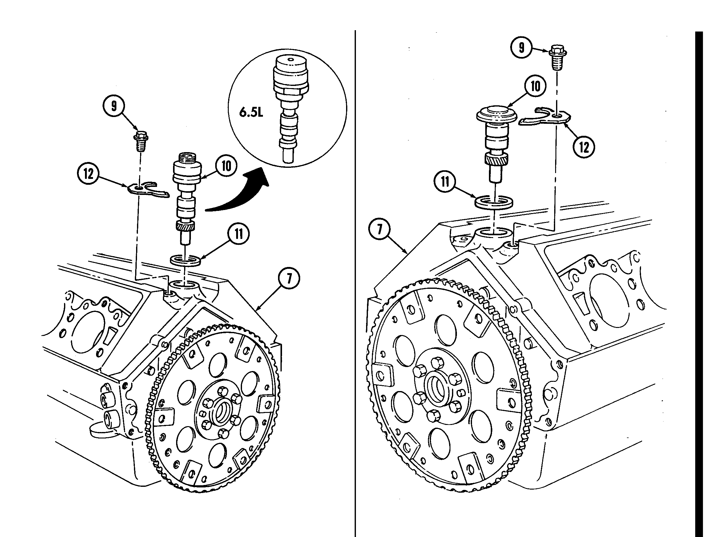
x. Oil Pump Drive
1. Remove capscrew (9) and clamp (12) from cylinder block (7).
2. Remove oil pump drive (10) and gasket (11) from cylinder block (7). Discard gasket (11).
TURBO ENGINE
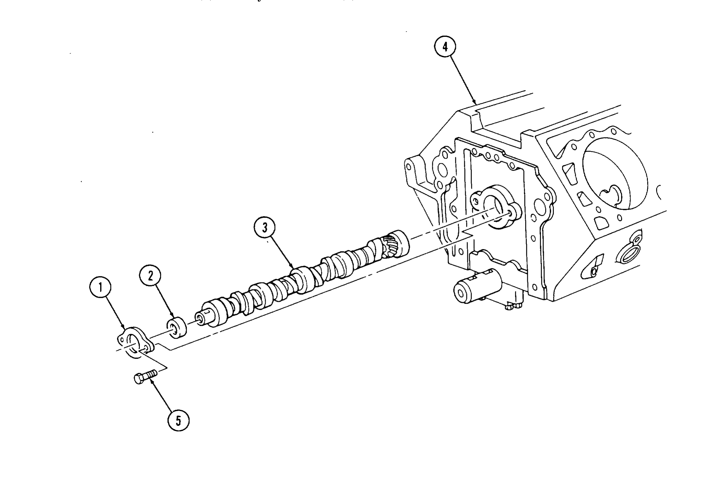
y. Camshaft
1. Remove two capscrews (5), camshaft thrust plate (1), and spacer (2) from cylinder block (4).
2. Remove camshaft (3) from cylinder block (4).
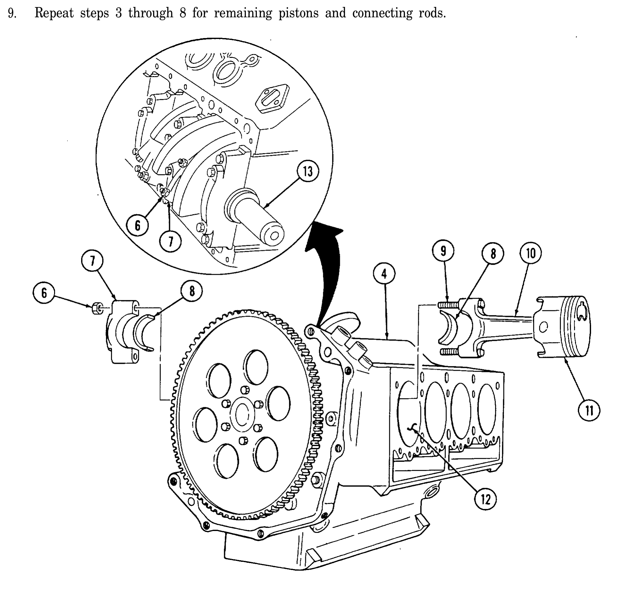
z. Pistons and Connecting Rods
1. Remove ridge from upper inside wall of each cylinder (12) with ridge reamer.
2. Rotate cylinder block (4) approximately 90°.
3. Rotate crankshaft (13) to gain access to two nuts (6).
4. Check sides of connecting rod (10) and rod cap (7) for matching identification numbers. If no numbers are present, stamp connecting rod (10) and rod cap (7) with cylinder number for assembly.
5. Remove two nuts (6) securing rod cap (7) to connecting rod (10) and remove rod cap (7) and two bearings (8). Discard bearings (8). 6, Cover connecting rod bolts (9) with 3/8-in. rubber hose.
7. Push connecting rod (10) and piston (11) out from the inside and remove from cylinder block (4).
8. Remove rubber hose from connecting rod bolts (9) and install rod cap (7) on connecting rod (10) and secure with nuts (6).
9. Repeat steps 3 through 8 for remaining pistons and connecting rods.
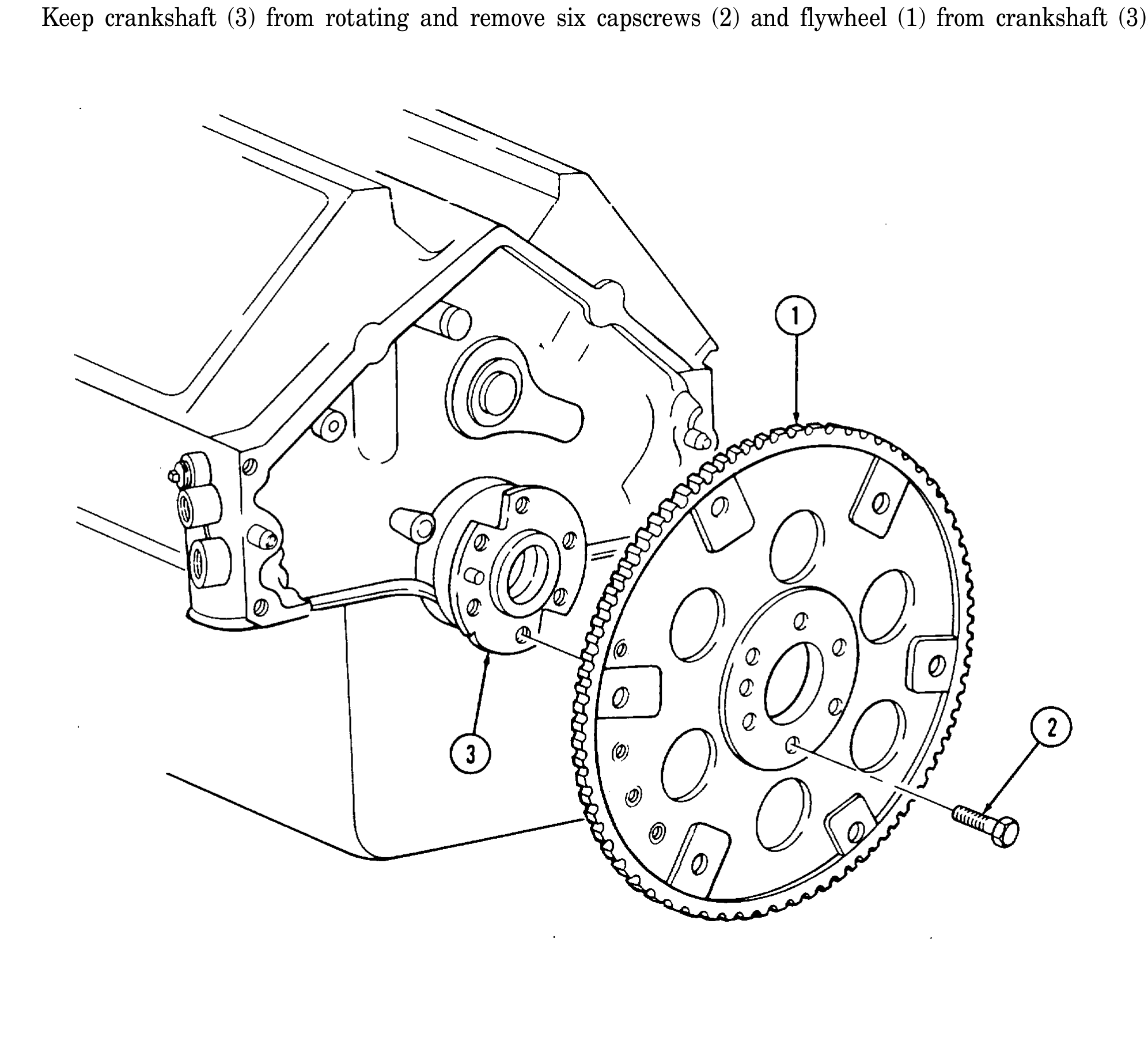
aa. Flywheel
Keep crankshaft (3) from rotating and remove six capscrews (2) and flywheel (1) from crankshaft (3).
bb. Crankshaft and Main Bearings
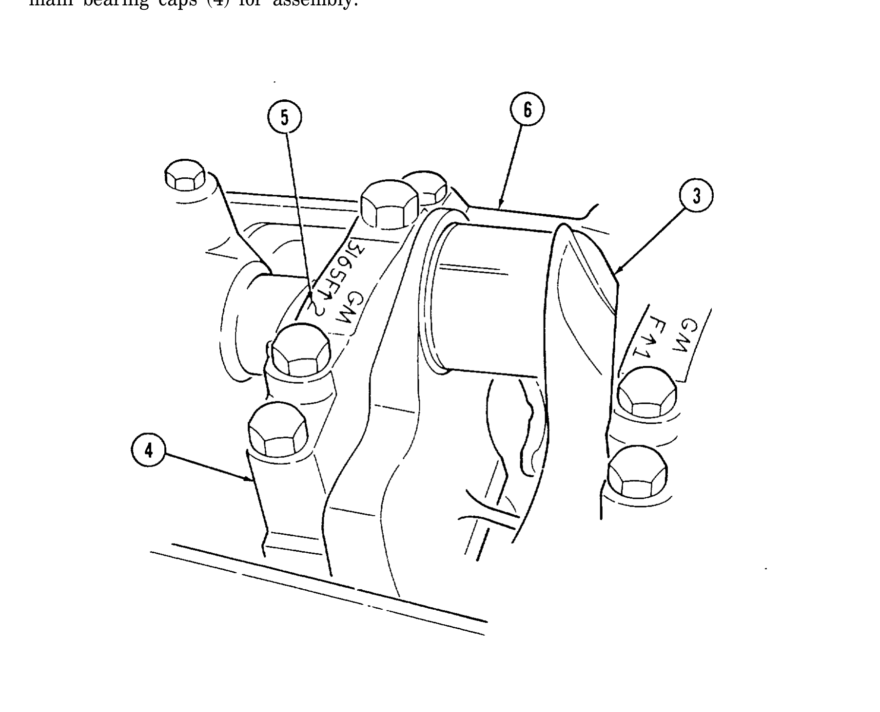
1. Rotate cylinder block (6) so crankshaft (3) faces upward.
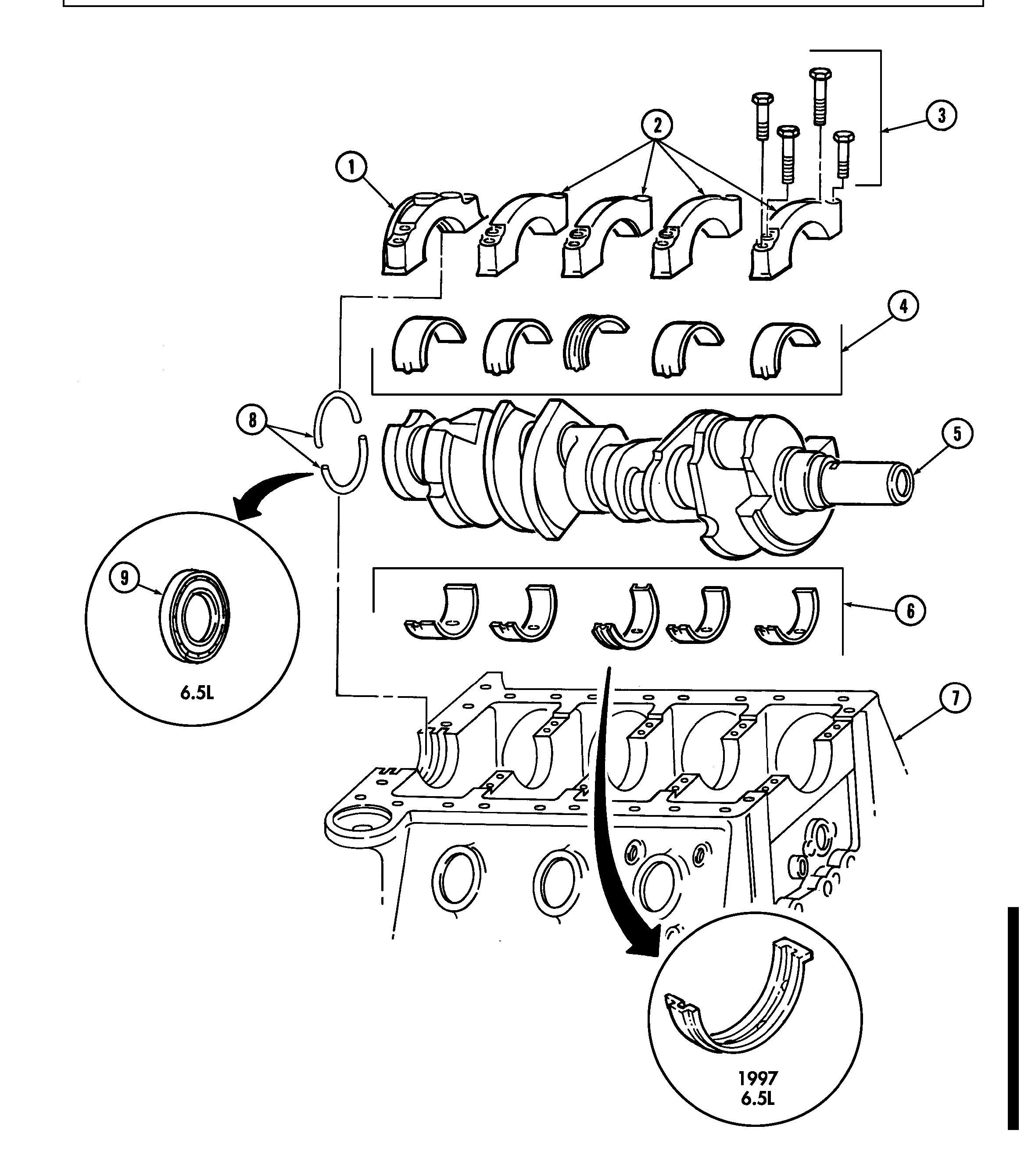
2. Check location numbers (5) on main bearing caps (4). If location numbers (5) are not clear, stamp main bearing caps (4) for assembly.
3. Remove one-piece crankshaft rear oil seal (9) from rear main bearing cap (1) and cylinder block (7). Discard one-piece crankshaft rear oil seal (9).
4. Remove four capscrews (3) securing main bearing cap (2) to cylinder block (7) and remove cap (2) and bearing (4). Discard bearing (4).
5. Repeat step (4) for remaining main bearing caps (2), rear main bearing cap (1), and bearings (4). WARNING. Crankshaft must be supported during removal and installation. Failure to support crankshaft may cause injury to personnel or damage to equipment.
6. Remove crankshaft (5) and bearings (6) from cylinder block (7). Discard bearings (6). WARNING. Gaskets installed on some 6.2L engines assembled prior to 1991 may contain asbestos. Gaskets should be removed with a scraper or putty knife and then be disposed of IAW current directives. Inhalation of asbestos fibers can cause respiratory ailments.
7. Remove two-piece crankshaft rear oil seal (8) from rear main bearing cap (1) and cylinder block (7). Discard two-piece crankshaft rear oil seal (8).
8. Install bearing caps (1) and (2) on cylinder block (7) and secure with twenty capscrews (3).