2-18. Connecting Rod and Piston Repair
TM 9-2815-237-34 · Chapter 2 — Engine Maintenance
This task covers:
a.    Disassembly                                    c. Inspection
b.    Cleaning                                       d. Assembly
INITIAL SETUP:
     Tools                                                Manual References
      General mechanic’s tool kit:                         TM 9-2815-237-34P
        automotive (Appendix E, Item 1)
      Feeler gauge (Appendix E, Item 13)                  Equipment Condition
      Micrometer (Appendix E, Item 16)                     Engine disassembled into subassemblies
      Piston ring expander (Appendix E, Item 20)           (para. 2-15).
     Materials/Parts
      Sixteen snaprings (Appendix D, Item 49)
      Eight piston ring sets
       (Appendix D, Item 37 or 48)
      Lubricating oil OE/HDO (Appendix B, Item 13)

a. Disassembly

 1.       Remove top compression ring (1), second compression ring (2), and oil ring (3) from piston (4).
          Discard rings (1), (2), and (3).
 2.       Remove two snaprings (5), piston pin (15), and connecting rod (13) from piston (4). Discard
          snaprings (5).
 3.       Remove two nuts (11) and rod cap (12) from connecting rod (13).
 4.       Repeat steps 1 through 3 for remaining pistons and connecting rods.

b. Cleaning

 Clean all components in accordance with para. 2-9.

c. Inspection

                                                        NOTE
                        • For general inspection instructions, refer to para. 2-10.
                        • To identify correct piston size for standard, Hi-Limit, and
                          oversize pistons, check code stamped on face of piston, and
                          determine correct piston size. Refer to para. 2-45, table 2-4, for
                          piston-cylinder specifications.
                        • 6.5L engines do not have Hi-Limit pistons.
 1.       Inspect piston (4) for cracks at ring lands (6), skirt (7), and pin bosses (16). Replace piston (4)
          if cracked.
 2.       Inspect piston (4) for scoring, galling, and scuffing. Replace if scored, galled, or scuffed.
 3.       Measure piston (4) at center (8) and bottom (9) of piston skirt (7) using micrometer. If measurement
          at bottom (9) is smaller than measurement at center (8), piston skirt (7) is collapsed and piston (4)
          must be replaced.
 4.       Inspect connecting rod (13) and rod cap (12) for distortion or damage. Replace connecting rod (13)
          if either are damaged or distorted.
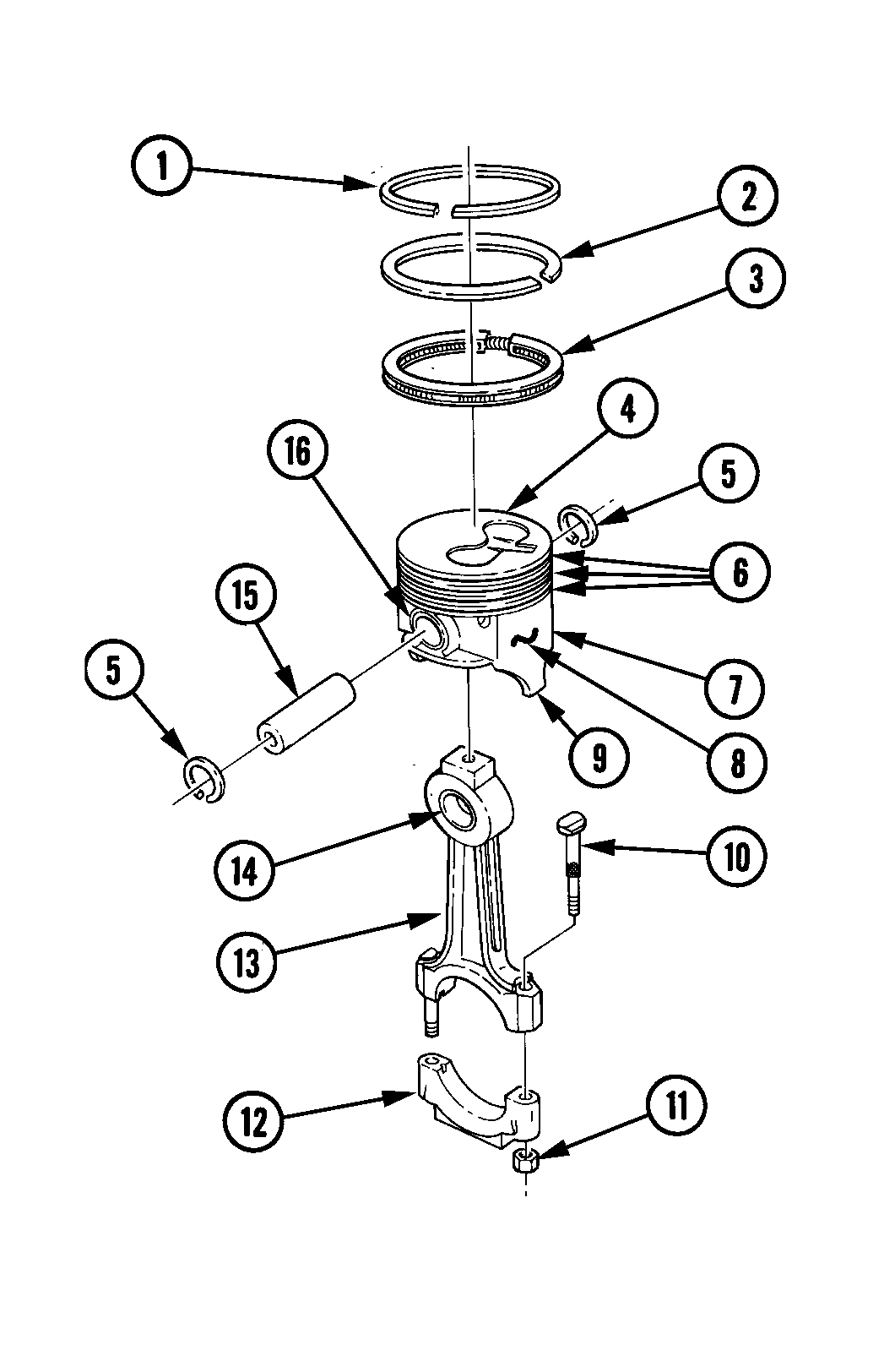
5. Inspect connecting rod bolts (10) and nuts (11) for damage. Replace if damaged.
6. Inspect bronze bushing (14) in small end of connecting rod (13) for damage. Replace connecting rod (13) if damaged.
7. Inspect piston pin (15) for galling, scoring, and damage. Replace piston (4) if scored, galled, or damaged.
8. Measure pin boss (16) inside diameter and piston pin (15) outside diameter to determine if clearance is within specifications (table 2-2 or 2-3). If measurement exceeds specifications, replace piston (4).
9. Measure piston pin (15) outside diameter and bushing (14) inside diameter to determine if fit to rod is within specifications (table 2-2 or 2-3). If measurement exceeds specifications, replace connecting rod (13).
10. Check ring groove clearance. If measurement exceeds specifications (table 2-2 or 2-3), replace piston (4).
11. Repeat steps 1 through 10 for remaining pistons and rods.
d. Assembly
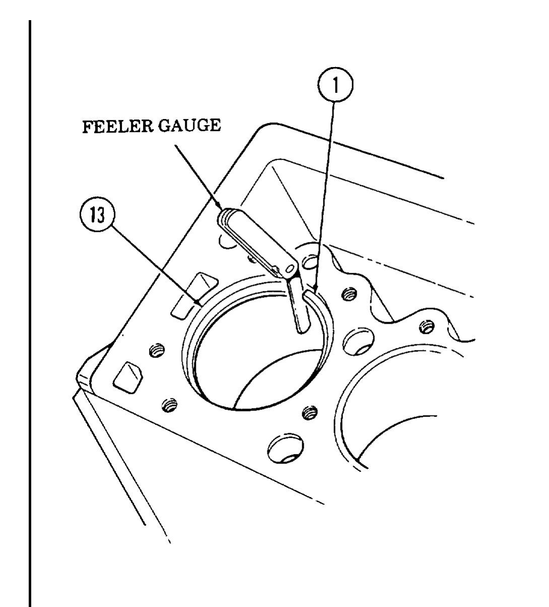
1. Place top compression ring (1) in cylinder bore (13) in which it will be used.
2. Slide piston ring (1) 1 in. (25.4 mm) into cylinder bore (13). Be sure piston ring (1) is square with cylinder bore (13).
3. Check gap in piston ring (1) using feeler gauge.
4. Top compression ring (1) end gap must be 0.012-0.022 in. (0.30-0.55 mm). If not, replace ring (1) and check gap.
5. Repeat steps 1 through 3 using second compression ring (2). End gap must be 0.030-0.039 in. (0.75-1.00 mm). If not, replace ring (2) and check gap.
6. Repeat steps 1 through 3 using oil ring (4). End gap must be 0.010-0.020 in. (0.25-0.51 mm). If not, replace ring (4) and check gap. Reinstall spring (3).
7. Repeat steps 1 through 6 for remaining piston rings.
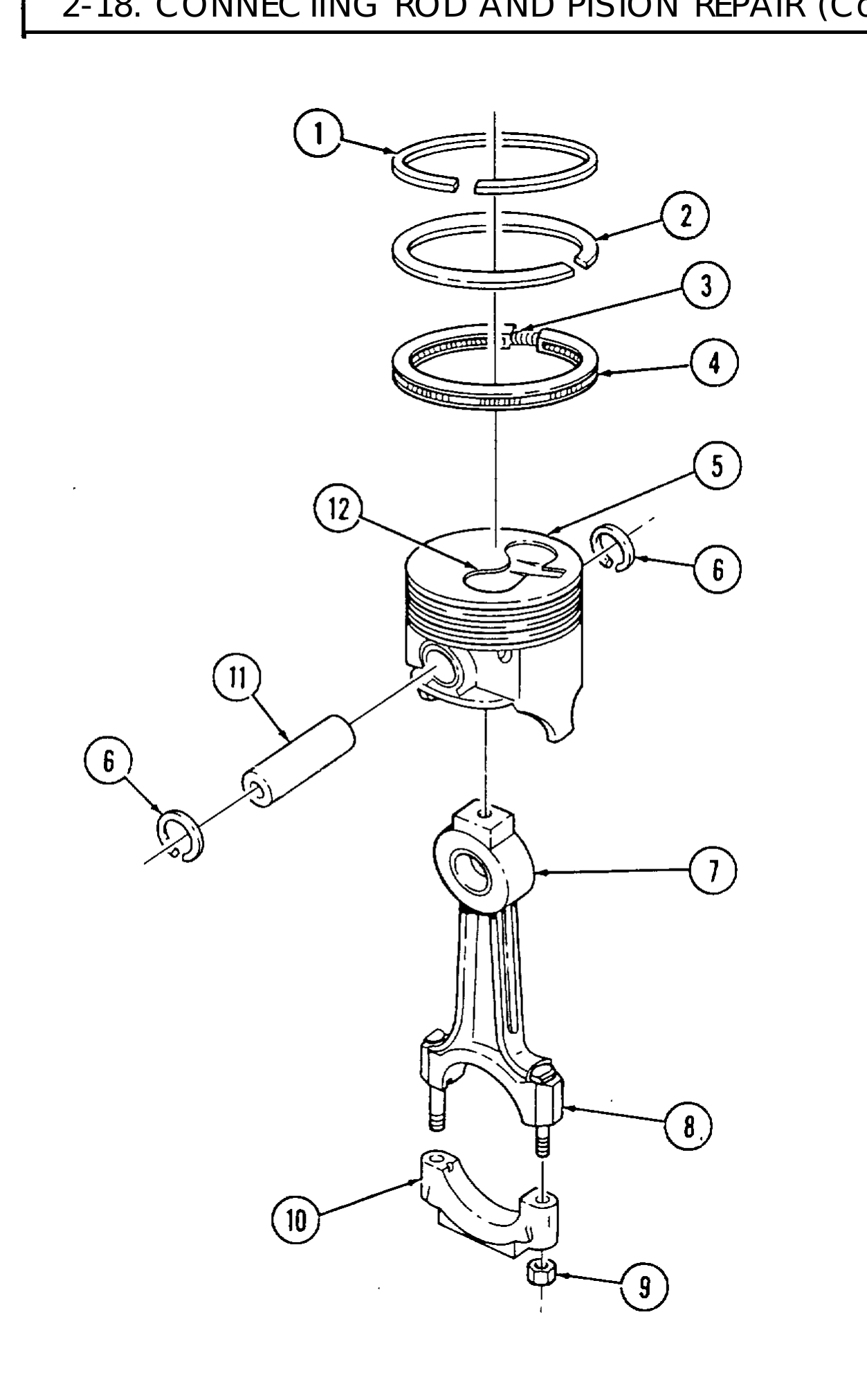
8. Install connecting rod (7) in piston (5) so that identification number (8) and depression (12) on top of piston (5) are on the same side.
9. Coat piston pin (11) with OE/HDO and install in piston (5) and connecting rod (7) and secure with two snaprings (6).
10. Using piston ring expander, install oil ring (4) on piston (5).
11. Using piston ring expander, install second compression ring (2) on piston (5). Be sure marked side of piston ring (2) faces up.
12. Using piston ring expander, install top compression ring (1) on piston (5). Be sure marked side of piston ring (1) faces up.
13. Install rod cap (10) on connecting rod (7) and secure with two nuts (9).
14. Repeat steps 8 through 13 for remaining pistons and connecting rods.