2-16. Cylinder Block Repair
TM 9-2815-237-34 · Chapter 2 — Engine Maintenance
This task covers:
a. Preinspection c. Inspection
b. Cleaning d. Repair
lNITIAL SETUP: Tools Manual References General mechanic’s tool kit: TM 9-2815-237-34P automotive (Appendix E, Item 1) Straightedge (Appendix E, Item 15) Equipment Condition Feeler gauge (Appendix E, Item 13) Engine disassembled into subassemblies Cylinder bore gauge (Appendix E, Item 14) (para. 2-15). Micrometer (Appendix E, Item 16) Cylinder boring machine General Safety Instructions (Appendix E, Item 17) ● Compressed air for cleaning purposes will not Cylinder honing unit (Appendix E, Item 18) exceed 30 psi (207 kPa). ● Protective clothing must be used with steam Special Tools cleaning. Camshaft bearing remover and installer ● Wear eyeshields when using compressed air.
(Appendix E, Item 12) Materials/Parts Six protective dust caps (Appendix D, Item 5) Lubricating oil OE/HDO (Appendix B, Item 13) Pipe sealing compound (Appendix B, Item 17) Sealing compound, anaerobic (Appendix B, Item 18) Sealing compound, high temperature (Appendix B, Item 21)
a. Preinspection
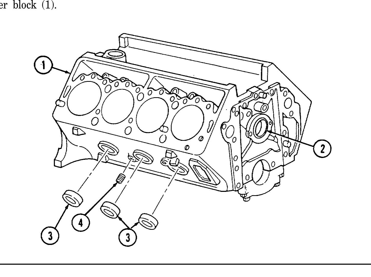
1. Inspect camshaft bearings (2) for chips, cracks, or scoring. If any bearing (2) is chipped, cracked, or scored, remove all camshaft bearings (2) (para. 2-16.d.3) and hot tank clean cylinder block (1) (para. 2-16.b.1).
2. Measure inside diameter of all camshaft bearings (2). Number one through number four camshaft bearings must be 2.167-2.170 in. (55.041-55.118 mm) and number five camshaft bearing (rear) must be 2.009-2.012-in. (51.028-51.104 mm). If any camshaft bearings (2) do not meet specifica- tions, replace all camshaft bearings (2) (para. 2-16.d.3) and hot tank clean cylinder block (1) (para. 2-16.b.1).
3. If all bearings (2) are to be reused, steam clean cylinder block (1) (para. 2-16.b.2).
b. Cleaning
1. Hot tank cleaning.
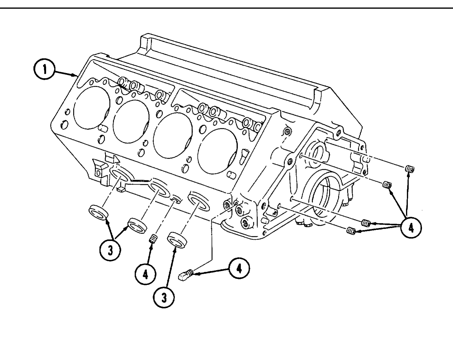
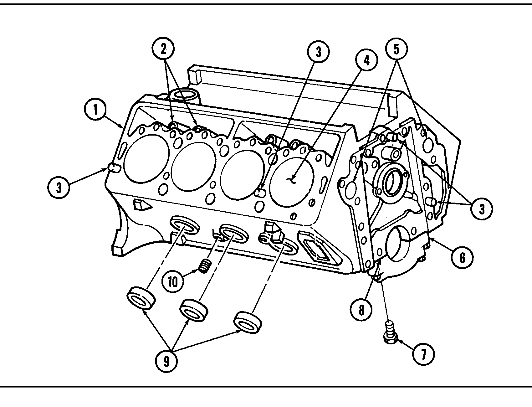
a. Remove six protective dust caps (3) and all plugs (4) from cylinder block (1).
b. Clean cylinder block (1) by submerging in tank of heated cleaning solution.
c. Run rods with brushes through all oil passages and repeat step 1.b.
d. Blow all dirt and cleaning solution from capscrew holes and oil passages with compressed air.
e. Refer to para. 2-9 for additional cleaning instructions.
f. Coat all cylinder bores, lifter bores, and machined surfaces with OE/HDO.
g. Apply pipe sealing compound to six protective dust caps (3) and all plugs (4) and install in cylinder block (1).
2. Steam cleaning.
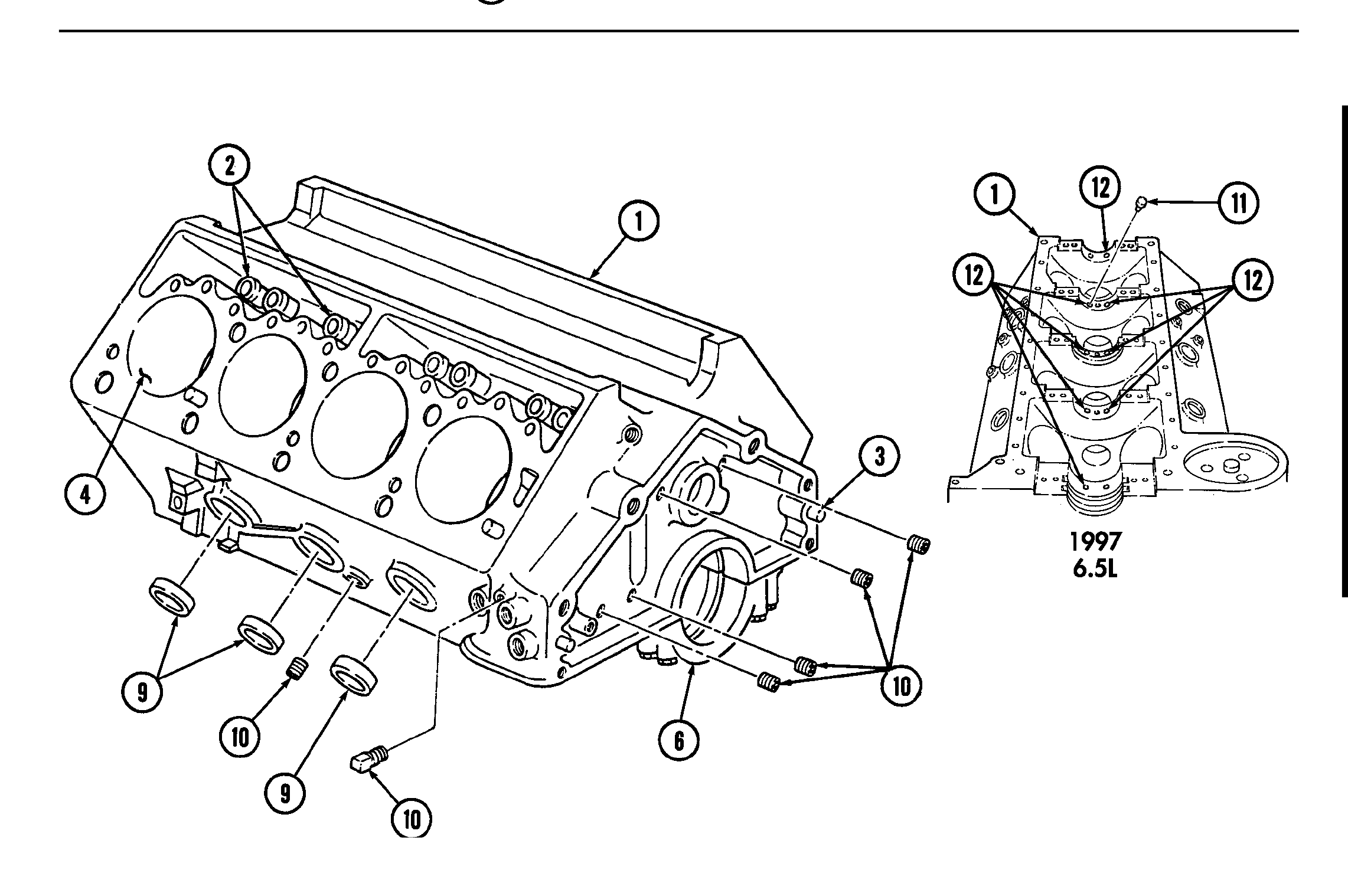
a. Remove six protective dust caps (9) and all plugs (10) from cylinder block (1).
b. Thoroughly steam clean cylinder block (1).
c. Run rods with brushes through all oil passages and repeat step b.
d. Blow all dirt and cleaning solution from capscrew holes and oil passages with compressed air.
e. Refer to para. 2-9 for additional cleaning instructions.
f. Coat all cylinder bores, lifter bores, and machined surfaces with OE/HDO.
g. Apply pipe sealing compound to six protective dust caps (9) and all plugs (10) and install in cylinder block (1).
c. Inspection
1. Inspect all surfaces and general overall condition of the cylinder block (1).
2. Visually check the cylinder block (1) for pitting in cylinder walls (4) and lifter bores (2). Replace engine if pitted or distorted.
3. Inspect the cylinder block (1) for cracks in cylinder walls (4), water jacket (5), lifter bores (2), and main bearing webs (8). Replace engine if cracked.
4. Inspect main bearing caps (6) for cracks, scoring, or damage. Replace engine if any are cracked, scored, or damaged.
5. Inspect main bearing cap bolts (7) for damage. Replace if damaged.
6. Inspect dowel pins (3) for damage. Replace if damaged.
7. Using a straightedge and feeler gauge, check flatness of cylinder head sealing surfaces on cylinder block (1). Flatness on cylinder block (1) must not vary more than 0.002 in. (0.051 mm) in a distance of 6 in. (15.2 mm) or more than 0.006 in. (0.152 mm) overall. Repair cylinder or replace engine if flatness does not meet above specifications.
7.1. Inspect piston oil nozzles (11) and bores (12) for damage. Replace piston oil nozzles (11) if damaged.
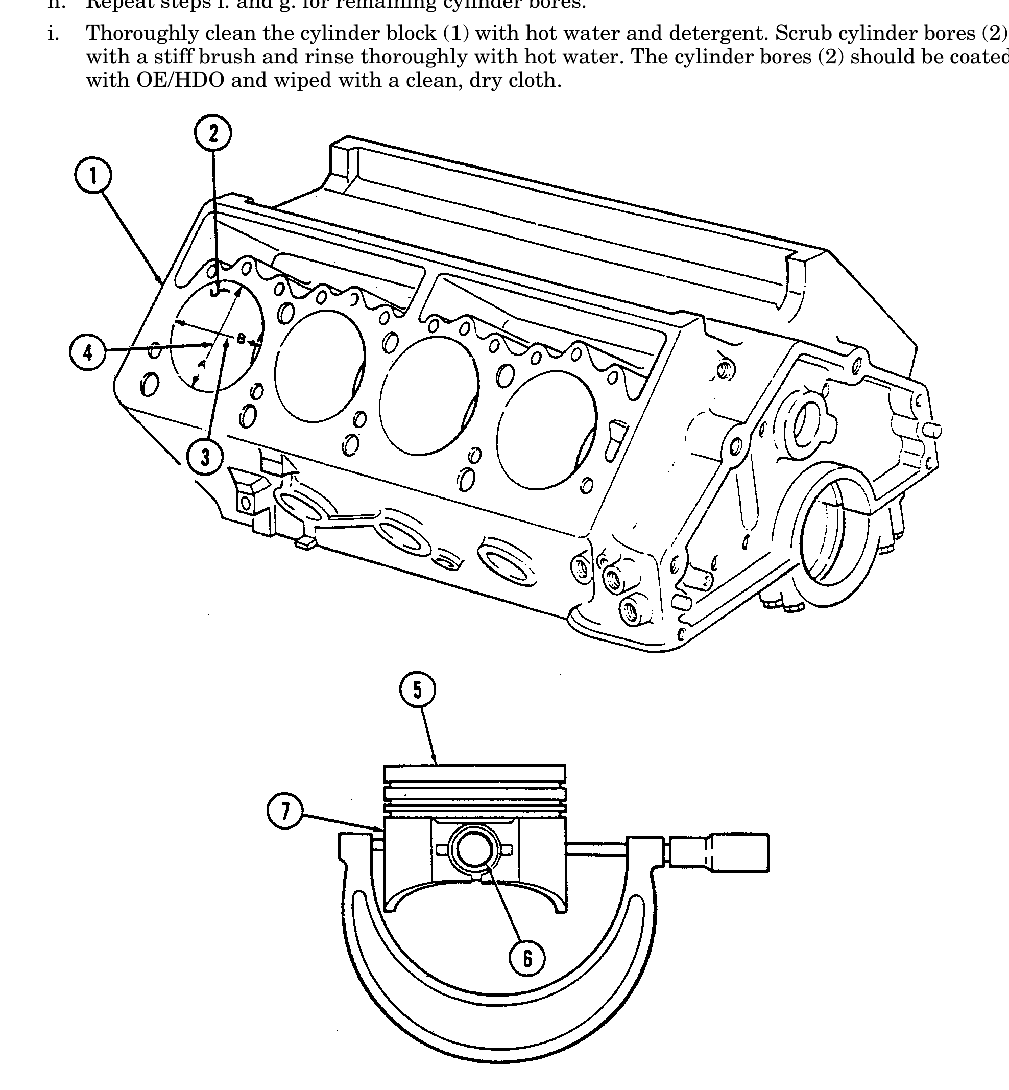
8. Using cylinder bore gauge, measure all cylinder bores (2) for taper. Measurements must be taken at point “A” (4) at top and bottom of cylinder bore (2). If any cylinder exceeds specifications (table 2-2 or 2-3) by 0.005 in. (0.127 mm) or more, repair cylinder or replace engine.
9. Using cylinder bore gauge, measure all cylinder bores (2) for out-of-round. Measurement must be taken at point “A” (4) and point “B” (3) at top and bottom of cylinder bore (2). If any cylinder exceeds specifications (table 2-2 or 2-3) by 0.005 in. (0.127 mm) or more, repair cylinder or replace engine.
10. Using cylinder bore gauge, measure all cylinder bores (2) for bore diameter. Measurement must be taken at point “A” (4) 2-1/2 in. (64 mm) from top of cylinder bore (2). If any cylinder exceeds specifications (table 2-2 or 2-3) by 0.005 in. (0.127 mm) or more, repair cylinder or replace engine.
d. Repair
1. Boring.
a. Before using any type of boring bar, the top of the cylinder block should be filed off to remove any dirt or burrs. This is very important. If not checked, the boring bar may be tilted, which would result in the rebored cylinder wall not being at right angles to the crankshaft.
b. Measure piston diameter of the piston to be used at the skirt across the center line of the piston pin.
c. Using a boring bar, bore the cylinder to the same diameter as the piston. Hone the cylinder to get proper piston-to-bore clearance.
d. Repeat steps b. and c. for remaining cylinders.
2. Honing.
a. Using cylinder bore gauge, measure cylinder bore (2) for cylinder bore diameter. Measurement must be taken at point “A” (4) 2-1/2 in. (64 mm) from top of cylinder bore (2).
b. Measure “piston diameter” of piston (5) removed from corresponding cylinder using a micro- meter at piston skirt (7) across center line of piston pin (6).
c. Subtract “piston diameter” from “cylinder bore diameter” to determine “piston-to-bore clearance”.
d. Repeat steps a. through c. for remaining cylinder bores and pistons.
e. If all cylinder bores (2) have proper “piston-to-bore clearance” of 0.004-0.005 in. (0.102-0.127 mm) or if proper “piston-to-bore clearance” may be obtained using a standard “Hi-Limit” piston or oversized piston, go to step f. If not, engine may be repaired using a cylinder sleeve (para. 2-16.d.2).
f. Using cylinder hone, refinish cylinder bore (2). Hone should be moved up and down at sufficient speed to obtain very fine uniform surface finish marks, in a cross-hatch pattern of approximately 45° to 65° included angle. The finish marks should be clean, not sharp, and free from imbedded particles and torn or folded material.
g. If a “Hi-Limit” piston or oversized piston (5) was fitted to a cylinder bore (2), permanently mark the piston (5) for the cylinder bore (2) to which it has been fitted.
h. Repeat steps f. and g. for remaining cylinder bores.
i. Thoroughly clean the cylinder block (1) with hot water and detergent. Scrub cylinder bores (2) with a stiff brush and rinse thoroughly with hot water. The cylinder bores (2) should be coated with OE/HDO and wiped with a clean, dry cloth.
2. Installation of cylinder sleeves.
a. Identify cylinders that require sleeves.
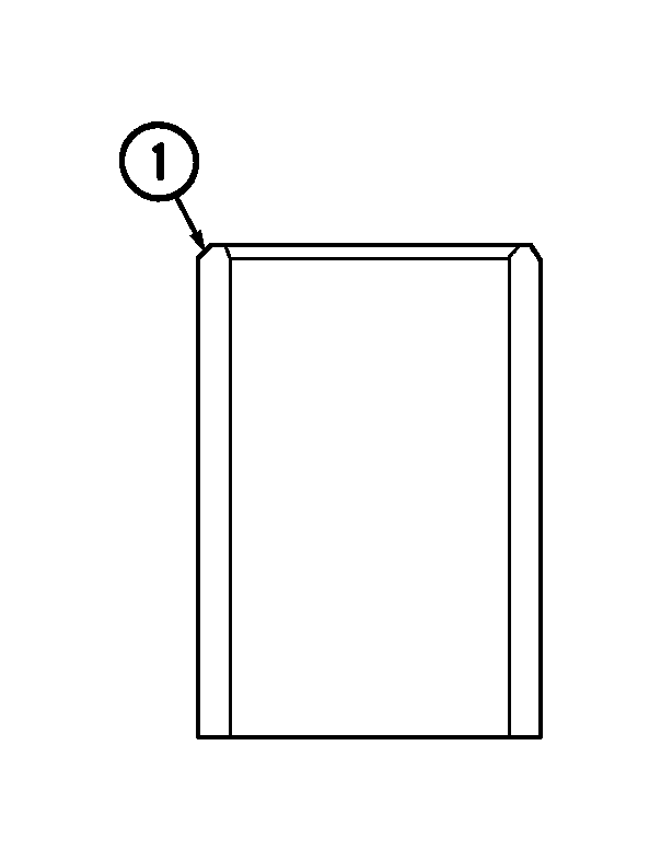
b. Using micrometer, measure outside diameter of cylinder sleeve (1).
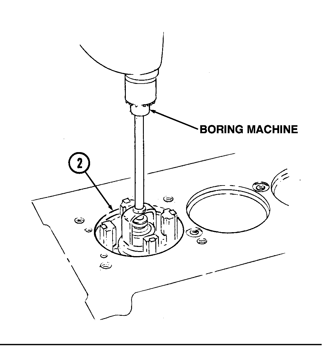
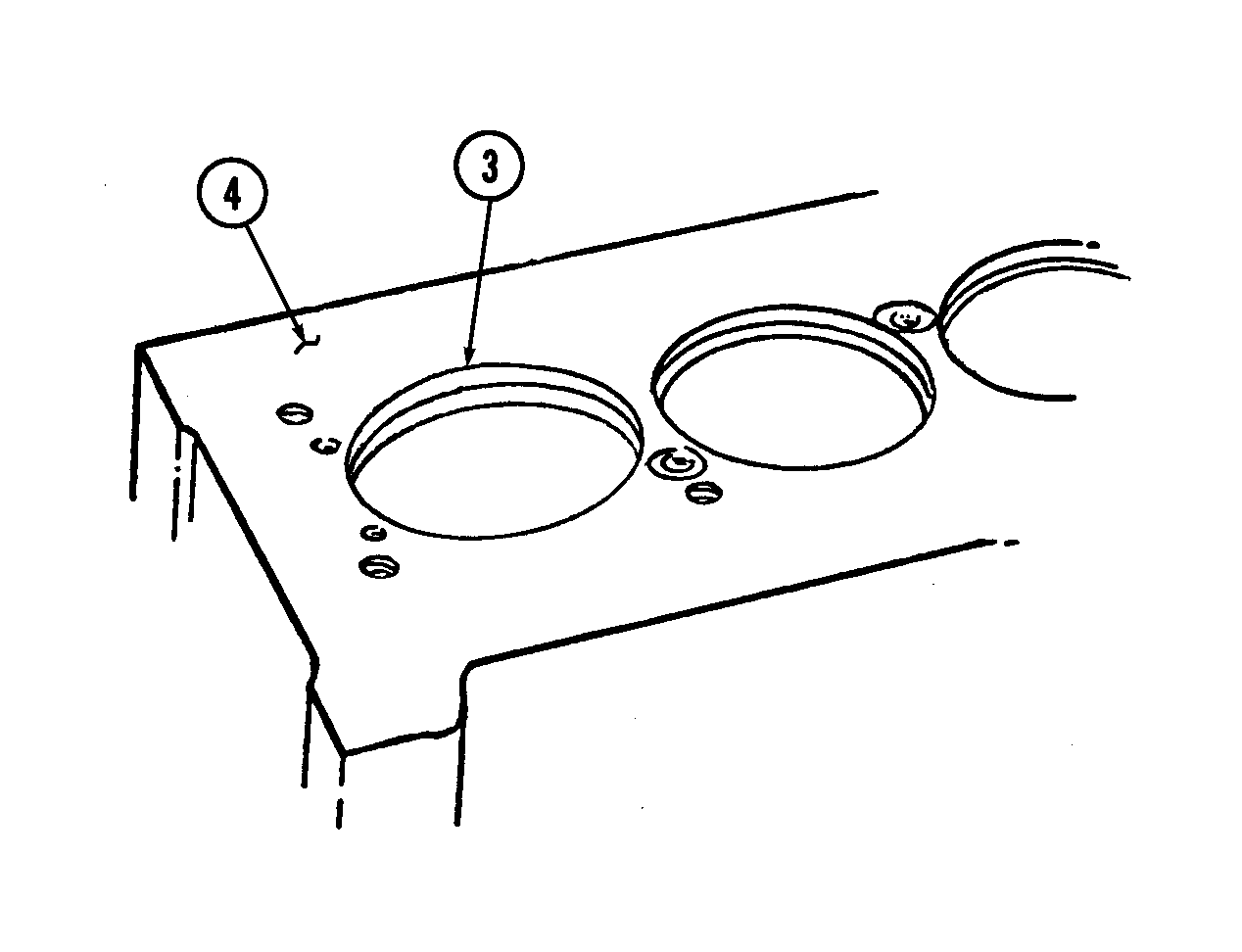
c. Using cylinder boring machine, bore cylinder (2) to diameter of sleeve (1) less 0.002 to 0.003 in. (0.051 to 0.076 mm) to create an interference fit between sleeve (1) and cylinder (2).
d. Apply bead of high temperature sealing compound to top and bottom of cylinder (2) bore. Press frozen sleeve (1) into cylinder (2) until it bottoms out on ledge at bottom of cylinder (2) bore.
e. Remove any excess sleeve material protruding above the head deck surface (4). Finish the sleeve (1) flush with deck of block (3), taking care not to damage deck surface (4).
f. Using cylinder boring machine, bore the sleeved cylinder (1) to appropriate piston size.
g. Finish cylinder surface (refer to para. 2-16.d.1).
3. Camshaft bearing replacement.
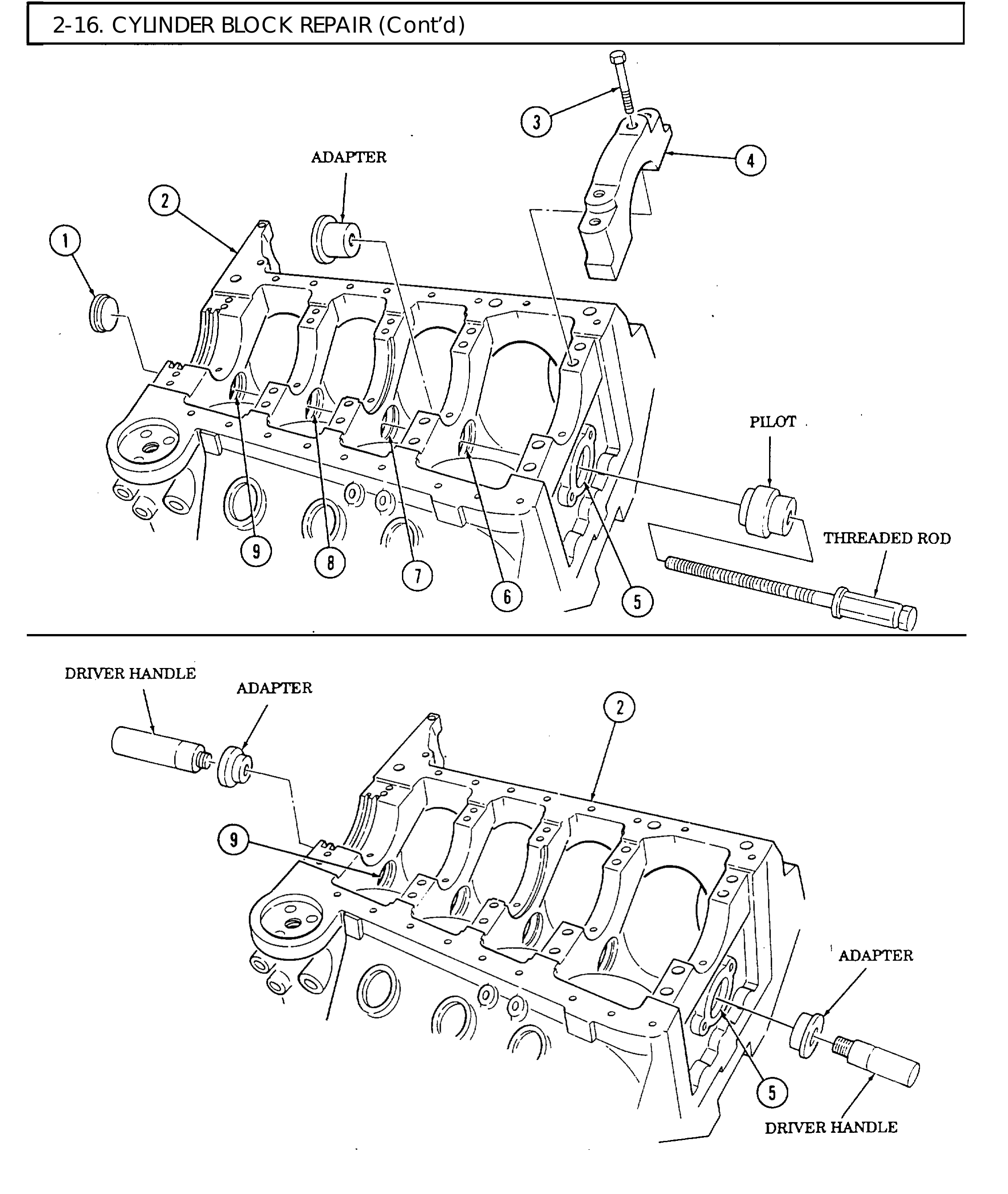
a. Remove cylinder block (2) from engine stand.
b. Remove twenty capscrews (3) and five main bearing caps (4) from cylinder block (2).
c. Drive camshaft rear plug (1) from cylinder block (2). Discard plug (1).
d. Install adapter J 6098-11 in camshaft bearing number two (6).
e. Install pilot in number one camshaft bearing (5). Insert threaded rod through pilot and thread into adapter.
f. Hold threaded rod stationary and tighten long hex nut to remove camshaft bearing (6) from cylinder block (2). When camshaft bearing (6) has been completely removed from cylinder block (2), remove threaded rod, pilot, and adapter. Discard bearing (6).
g. Repeat steps d. through f. for number three camshaft bearing (7).
h. Repeat steps d. through f., working from rear of cylinder block (2), for number four camshaft bearing (8).
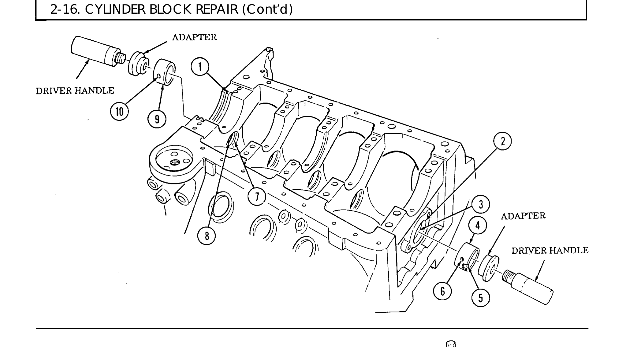
i. Using driver handle and adapter J6098-11, remove number one camshaft bearing (5) from cylinder block (2). Discard bearing (5).
j. Using driver handle and adapter J 6098-12, remove number five camshaft bearing (9) from cylinder block (2). Discard bearing (9).
half of the block face, when viewed with the block in an upside down position, or engine damage will result. ● The front bearing has an additional oil hole which will be located
between the six and seven o’clock positions. This bearing also has a notch which must be positioned toward the front of the block, or engine damage will result. ● All oil holes in camshaft bearings must be aligned with grooves
in camshaft bearing bores after installation, or engine damage will result.
k. Using driver handle and adapter J 6098-11, align number one camshaft bearing (4) so oil hole (5) is facing down and oil hole (6) is at or near the ten o’clock position and install into cylinder block (1). Remove installation tools and check to be sure oil holes (5) and (6) align with groove (3) in bearing bore (2).
1. Using driver handle and adapter J 6098-12, align number five camshaft bearing (9) so oil hole (10) is at or near the ten o’clock position and install into cylinder block (1). Remove installation tools and check to be sure oil hole (10) is aligned with groove (7) in bearing bore (8).
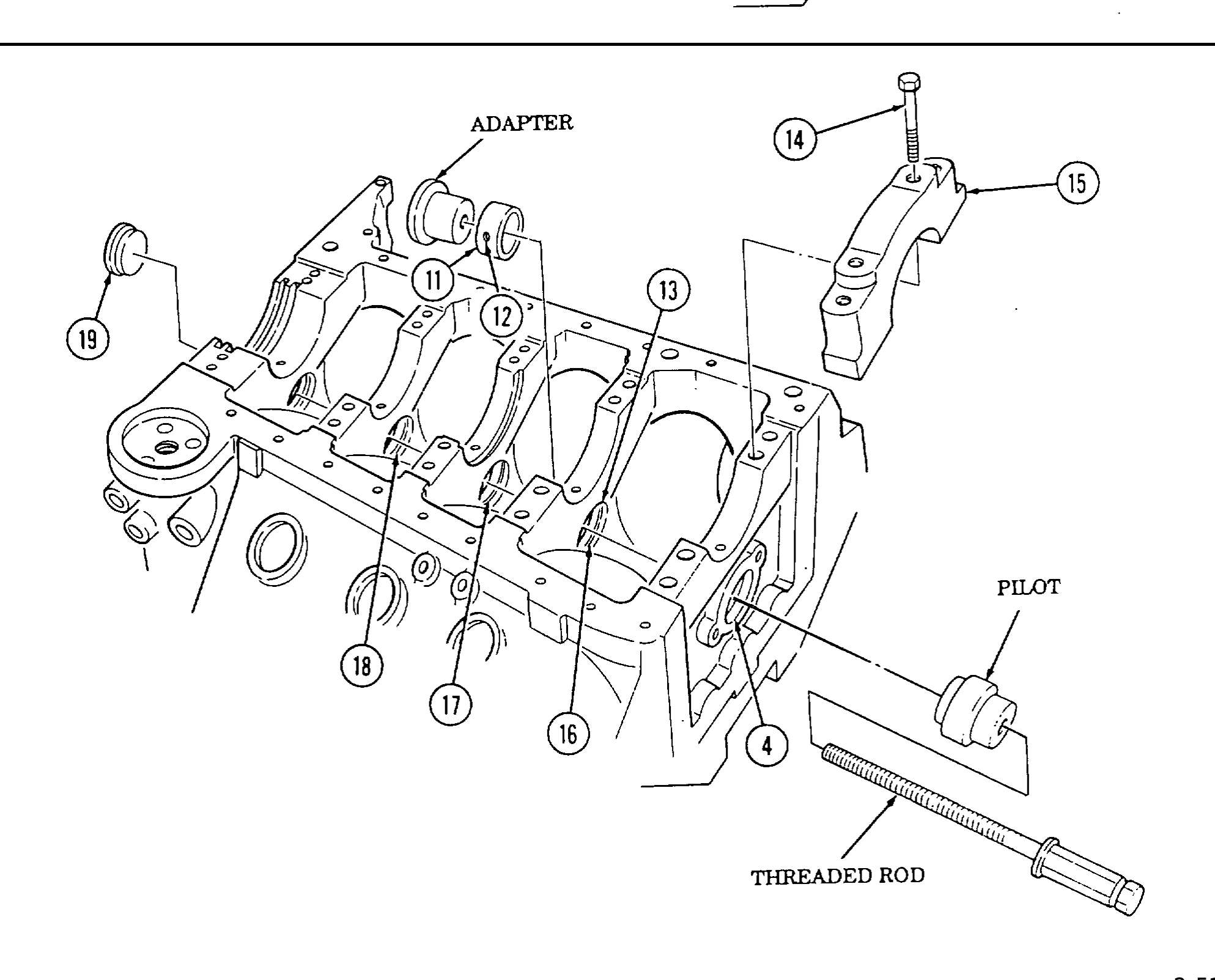
m. Install number two camshaft bearing (11) on adapter J 6098-11 and position in cylinder block (1) so oil hole (12) is at or near the ten o’clock position. Install pilot in number one camshaft bearing (4) and install threaded rod through pilot and thread into adapter.
n. Hold threaded rod stationary and tighten long hex nut to install camshaft bearing ( 11) in cylinder block (1), remove installation tools, and check to be sure oil hole (12) is aligned with groove (16) in bearing bore (13).
o. Repeat steps m. and n. for number three camshaft bearing (17).
p. Working from rear of cylinder block (1), repeat steps m. and n. for number four camshaft bearing (18).
q. Apply anaerobic sealing compound to outside diameter of rear plug (19) and install in cylinder block (1) until flush or 1/32-in. (0.79 mm) deep.
r. Install five main bearing caps (15) on cylinder block (1) and secure with twenty capscrews (14).
s. Install cylinder block (1) on engine stand.