Power Take-Off (PTO) Replacement
TM 9-2320-363-34-1 · Chapter 11 — Winch Maintenance
This task covers: a. Removal b. Cleaning c. Inspection d. Installation
Applicable Configuration:                           Equipment Condition:

All except M915A2                                   Reference                Condition Description
Tools and Special Equipment:                        TM 9-2320-363-20         Air System Drained
Tool Kit, SC 5180-95-CL-N05                         TM 9-2320-363-20         Transmission Tunnel
                                                                             Access Cover Removed
Materials/Parts:
                                                    General Safety lnstructions:
Kit                         P/N 328170-101X
Gasket                      P/N 23016683
                                                                      WARNING
Washer, Lock                                               Spilled transmission fluid is
                                                           very   slippery. Wipe   up   any
References:                                                spilled fluid immediately.
TM 9-2320-363-20                                           Failure to do so could result in
                                                           serious injury to personnel.

                                                                             M916A1/M916A2
                                                                             HYDRAULIC
                                                                             PUMP SHOWN

                                             NOTE
                      Tag air hoses prior to removal to aid in installation.

1.    DISCONNECT TWO AIR HOSES (1 AND 2).

                                         WARNING
         Spilled transmission fluid is very slippery. Wipe up any spilled fluid
         immediately. Failure to do so could result in serious injury to personnel.

2.    DISCONNECT LUBRICATION HOSE (3).
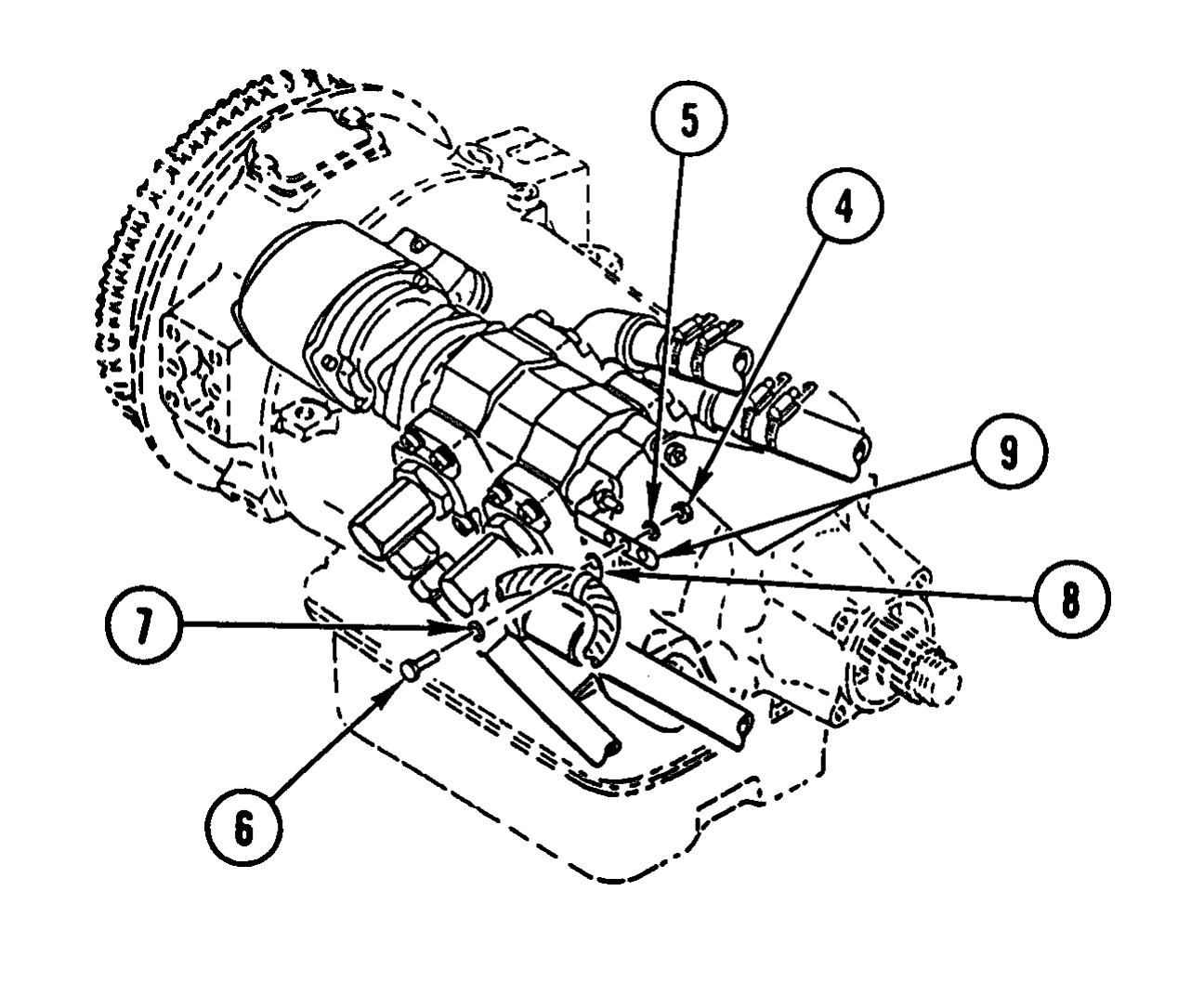
3. REMOVE NUT (4), WASHER (5), SCREW (6), WASHER (7), AND CLAMP (8) FROM BRACKET (9).
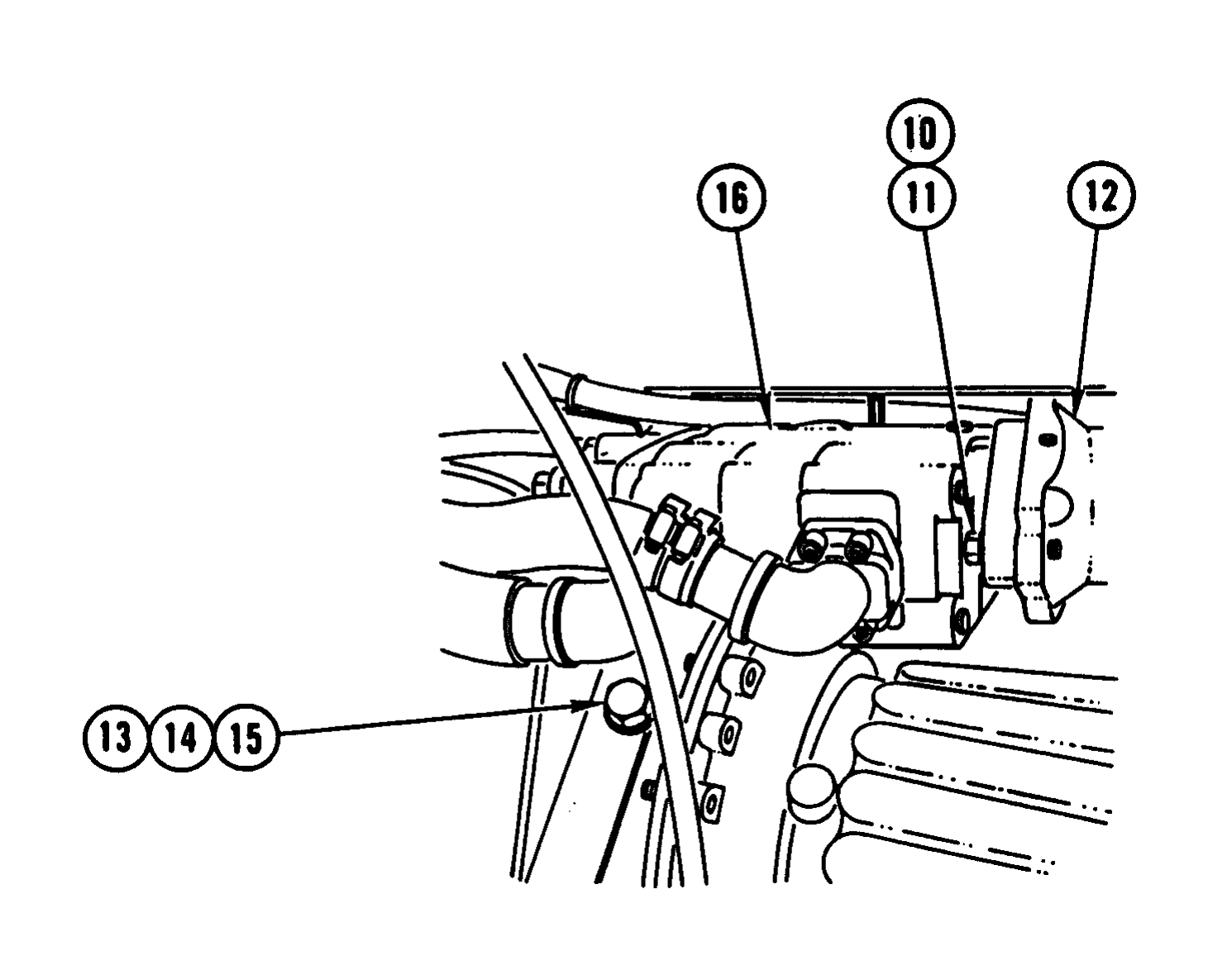
4. REMOVE TWO BOLTS (10) AND TWO WASHERS (11) FROM PTO (12).
5. REMOVE TWO BOLTS (13), TWO WASHERS (14), AND TWO LOCK WASHERS (15) AND MOVE HYDRAULIC PUMP (16) AWAY FROM PTO (12) APPROXIMATELY 0.75 IN. (19 mm). DISCARD LOCK WASHERS.
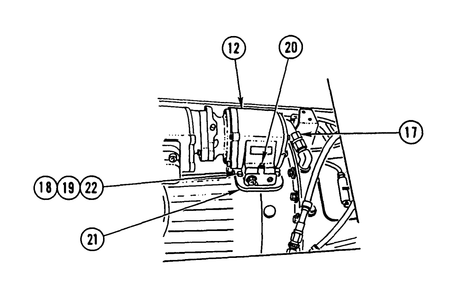
6. DISCONNECT HOSE (17).
7. REMOVE AND DISCARD FIVE NUTS (18), FIVE COPPER GASKETS (19), AND CAPSCREW (20).
8. REMOVE PTO (12) AND GASKET (21). DISCARD GASKET.
9. REMOVE AND DISCARD FIVE STUDS (22).
Use general cleaning methods to clean all parts (page 2-30).
Inspect all parts for wear or damage.
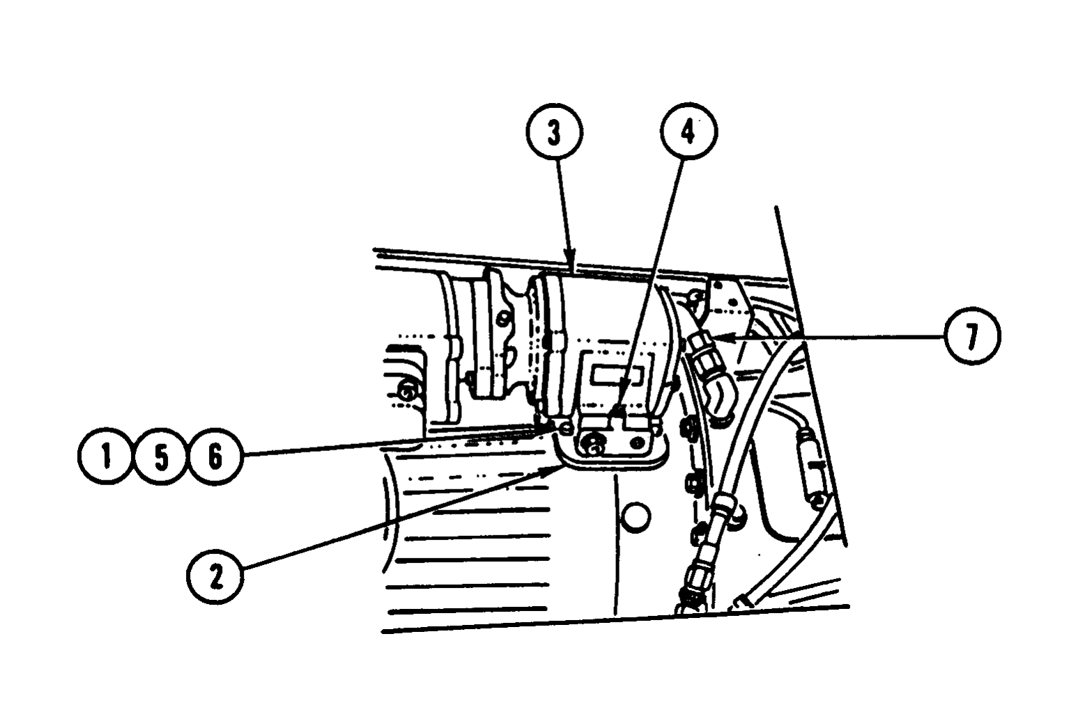
1. INSTALL FIVE NEW STUDS (1).
2. INSTALL NEW GASKET (2) AND PTO (3).
3. INSTALL NEW CAPSCREW (4), FIVE NEW COPPER GASKETS (5), AND FIVE NEW NUTS (6).
4. CONNECT HOSE (7).
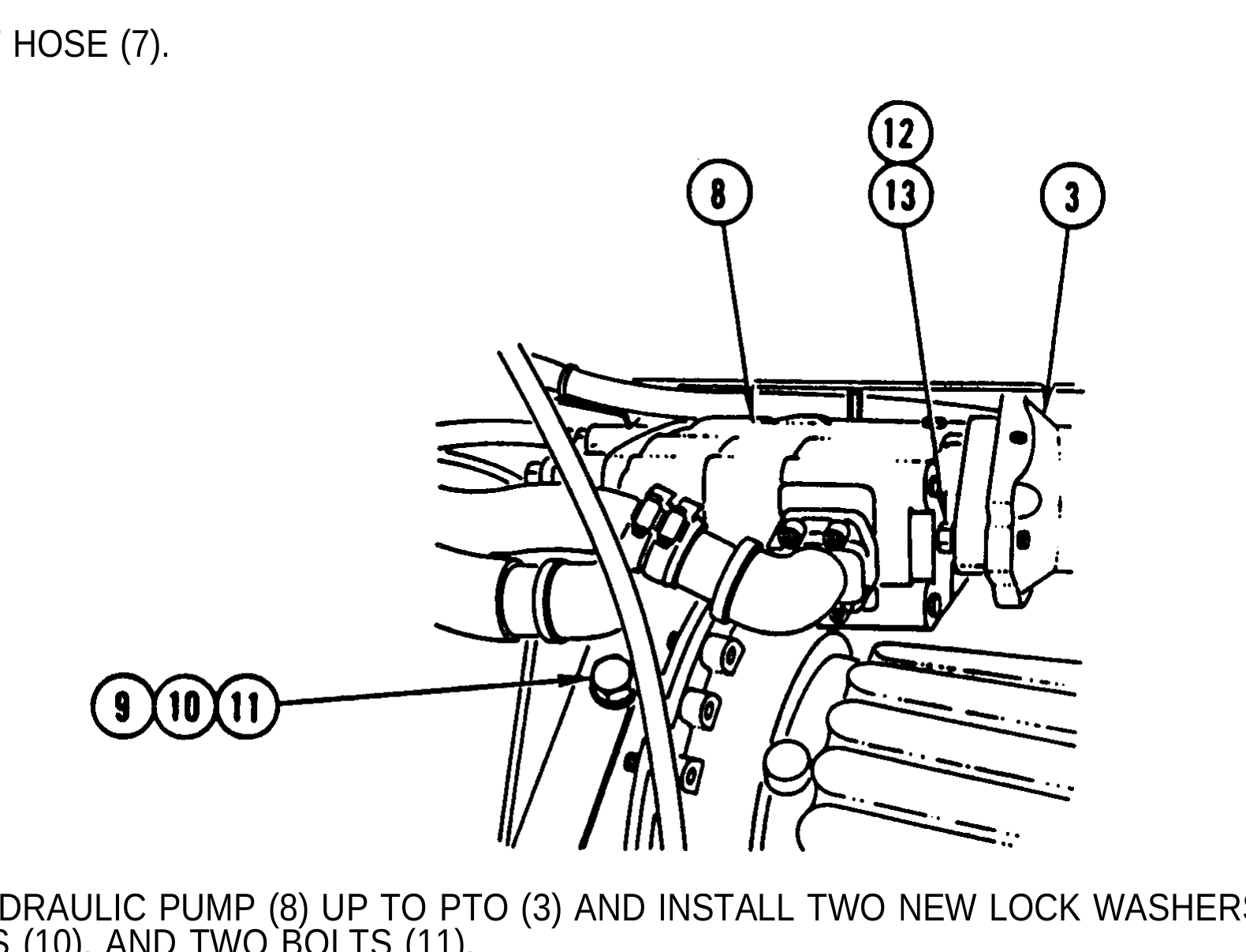
5. MOVE HYDRAULIC PUMP (8) UP TO PTO (3) AND INSTALL TWO NEW LOCK WASHERS (9), TWO WASHERS (10), AND TWO BOLTS (11).
6. INSTALL TWO WASHERS (12) AND TWO BOLTS (13).
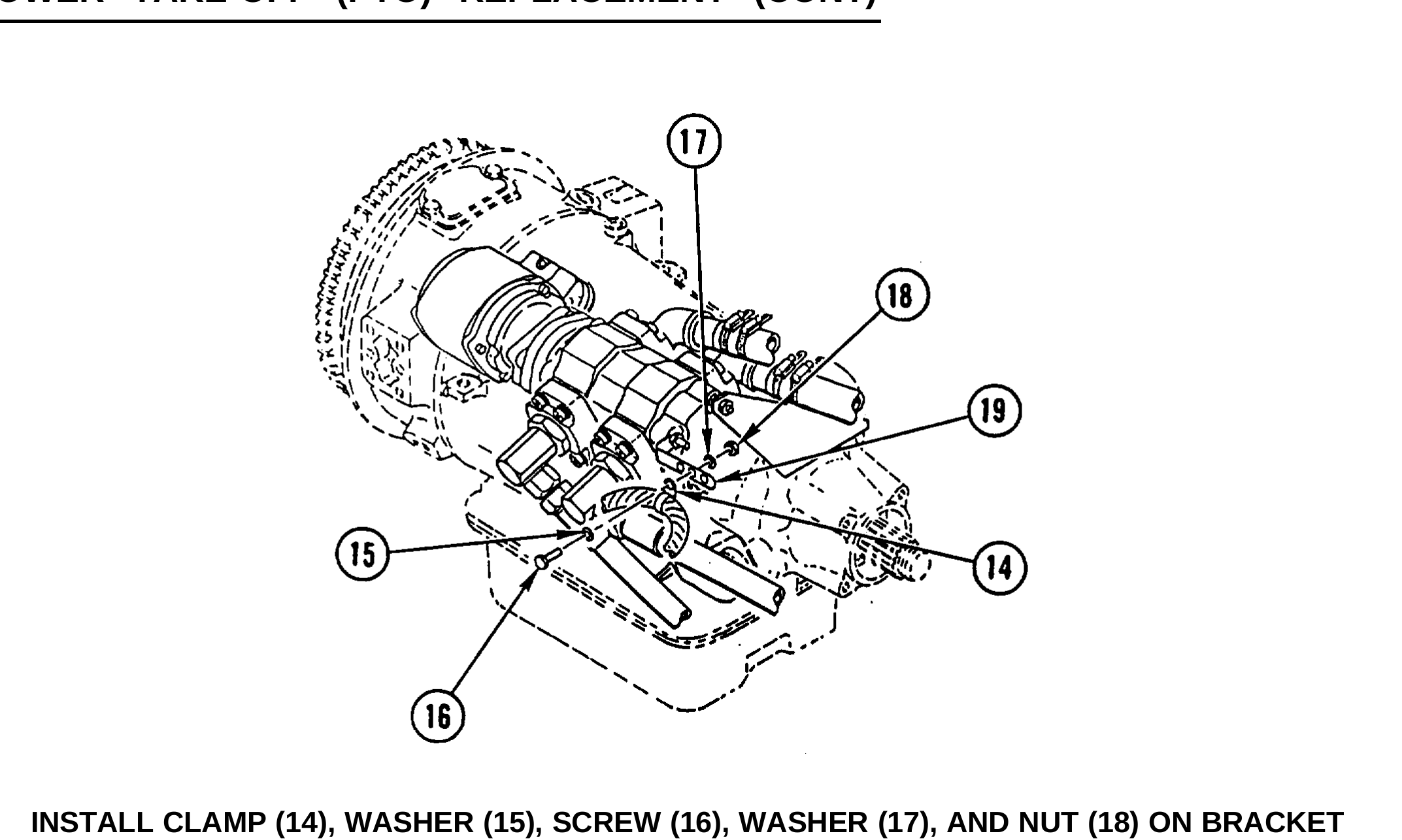
7. INSTALL CLAMP (14), WASHER (15), SCREW (16), WASHER (17), AND NUT (18) ON BRACKET (19).
Spilled transmission fluid is very slippery. Wipe up any spilled fluid immediately. Failure to do so could result in serious injury to personnel.
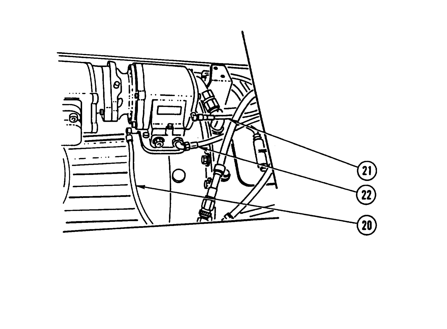
8. CONNECT LUBRICATION HOSE (20).
9. CONNECT TWO AIR HOSES (21 AND 22).
Install transmission tunnel access cover (TM 9-2320-363-20).
11-47/(11-48 Blank)
This chapter illustrates and describes procedures for maintenance of the air conditioning system. A list of tasks contained in this chapter is shown below.
Page
Air Conditioning System Refrigerant (R-134a) Maintenance (All Except M915A2 and M916A1) ............................................... 11.1-2
Air Conditioner Compressor Replacement (All Except M915A2 and M916A1) .............................................................. 11.1-9
Air Compressor Receiver-Drier Replacement (All Except M915A2 and M916A1) ........................................................ 11.1-14
Air Conditioner Condenser Replacement ( A l l E x c e p t M 9 1 5 A 2 a n d M 9 1 6 A 1 ) ............................................ 11.1-16
Air Conditioner Hose Replacement (All Except M915A2 and M916A1) .............................................. 11.1-18
Air Conditioner Fan Cycling Switch Replacement (All Except M915A2 and M916A1) ................................. 11.1-21
Air Conditioner Compressor Service (All Except M915A2 and M916A1) ............................... 11.1-23
AIR   CONDITIONING             SYSTEM       REFRIGERANT          (R-134a)         MAINTENANCE

This task covers:        a. Recovery b. Evacuating/Recycling         c. Purging      d. Flushing
                         e. Charging

Applicable Configuration:                                Equipment Description:

All except M915A2 and M916A1                             Reference                Condition Description

Tools and Special Equipment:                            TM 9-2320-363-10          Vehicle Blocked

Shop Equipment, SC 4910-95-CL-A31                        General Safety Instructions:
Tool Kit, SC 5180-90-CL-N26
Gage, Oil Level, 99-431
Recovery and Recycling System, 34400                                         WARNING
                                                            l   Use care to prevent refrigerant from
Materials/Parts:                                                touching your skin or eyes, because
                                                                liquid refrigerant, when exposed to air,
Receiver-Drier           P/N 088335-00                          quickly evaporates and will freeze skin
Cap and Plug Set         Appendix B, Item 7.1                   or eye tissue.        Serious injury or
Loctite                  Appendix B, Item 33                    blindness could result if you come in
Oil, Refrigerant         Appendix B, Item 43.1                  contact with liquid refrigerant.
Refrigerant, R-134a      Appendix B, Item 48.1
                                                            l   Refrigerant R-134a air conditioning
References:                                                     systems should not be pressure tested
                                                                or leak tested with compressed air.
TM 9-2320-363-10                                                Combustible mixtures of air and R-134a
TM 9-2320-363-20                                                m a y f o r m , resulting in a fire or
                                                                explosion, which could cause personal
                                                                injury.

1.       REMOVE THE CAPS FROM THE SUCTION AND DISCHARGE SERVICE VALVES. VALVES ARE
         LOCATED AT THE FIREWALL ON THE PASSENGER’S SIDE OF THE VEHICLE.

2.       WEARING PROTECTIVE GOGGLES AND NON-LEATHER GLOVES, ATTACH THE
         RECOVERY/RECYCLING STATION’S HOSES TO THE VALVES.

                                                NOTE
         Push down firmly on the hose connectors until a clicking sound is heard. This will ensure
         that the coupler is locked.

         a.      MAKE SURE THAT THE RECOVERY AND RECYCLING STATION’S VALVES ARE
                 CLOSED.
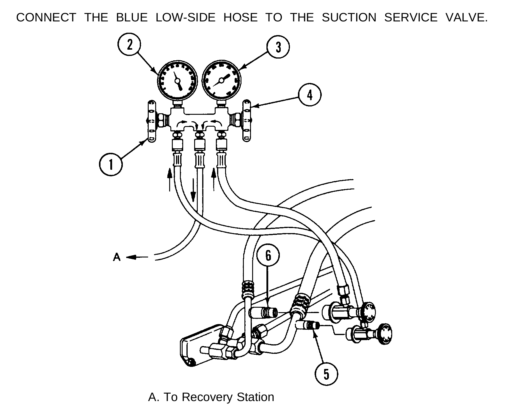
b. CONNECT THE RED HIGH-SIDE HOSE TO THE DISCHARGE SERVICE VALVE.
c. CONNECT THE BLUE LOW-SIDE HOSE TO THE SUCTION SERVICE VALVE.
A. To Recovery Station
1. Manifold Suction Hand Valve (Open)
2. Low-Side Gauge
3. High-Side Gauge
4. Manifold Discharge Hand Valve (Open)
5. Suction Service Valve
6. Discharge Service Valve
d. TURN THE KNOB CLOCKWISE ON EACH COUPLER TO OPEN THE SCHRADER VALVES.
3. FOLLOW THE RECOVERY AND RECYCLING STATION MANUFACTURERS INSTRUCTIONS AND RECOVER ALL OF THE REFRIGERANT FROM THE SYSTEM.
l Always comply with all local regulations regarding refrigerant disposal. You may be subject to substantial penalties for improper disposal.
l Any time air conditioning system refrigerant is evacuated, replace receiver-drier.
4. REPLACE RECEIVER-DRIER (page 11.1-14).
If the system is contaminated with moisture, all of the compressor oil must be replaced with clean oil. If the system is heavily contaminated with desiccant or grit, replace the compressor and expansion valve.
5. SERVICE AIR CONDITIONER COMPRESSOR (page 11.1-23).
AIR CONDITIONING SYSTEM REFRIGERANT (R-134a) MAINTENANCE (CONT)
The system must have been recovered and the compressor filled with the correct amount of refrigerant oil. Replace the receiver-drier if the system is opened.
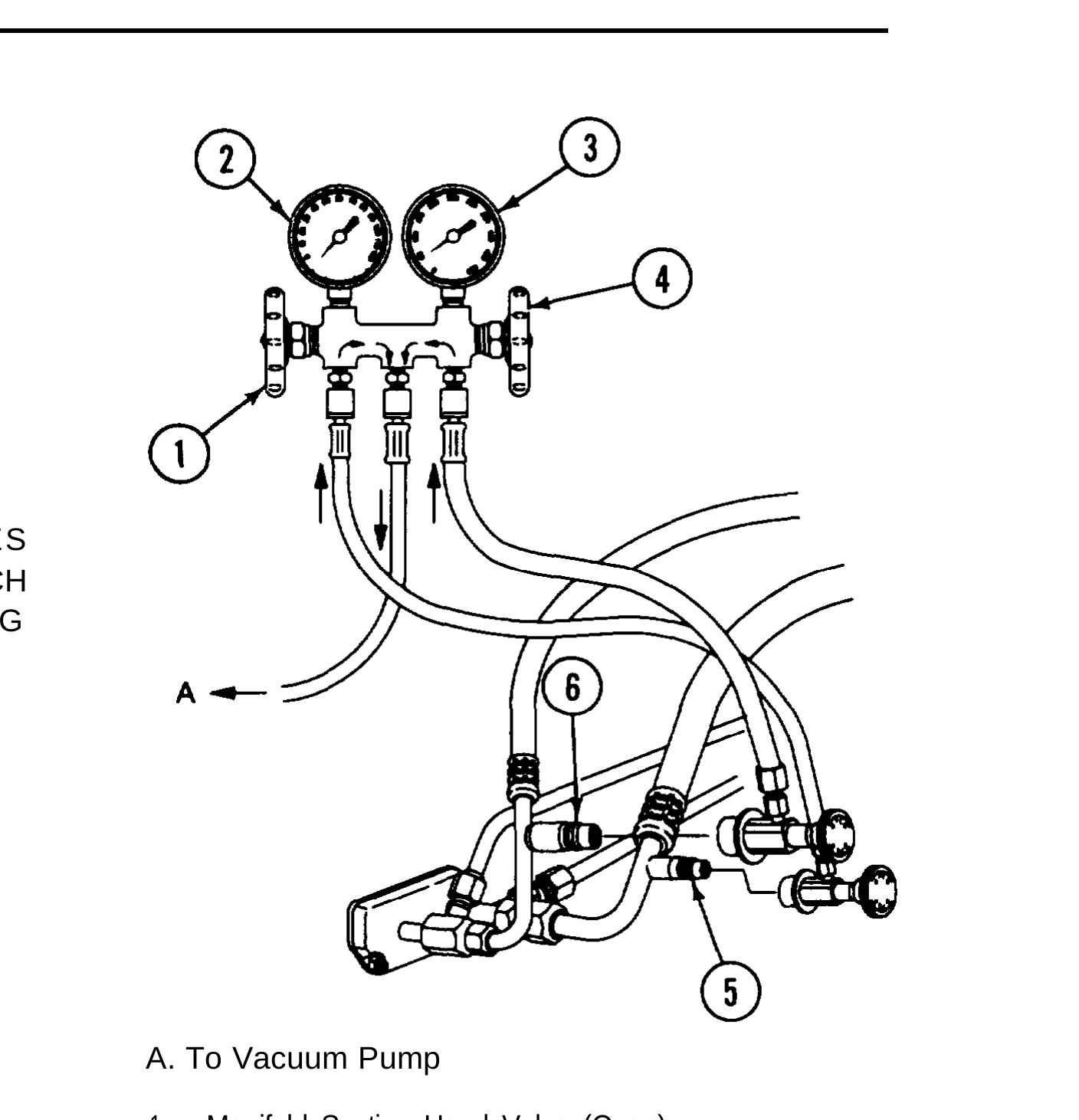
1. WEARING PROTECTIVE GOGGLES AND NON-LEATHER GLOVES, ATTACH THE RECOVERY/RECYCLING STATION’S HOSES TO THE VALVES.
A. To Vacuum Pump
1. Manifold Suction Hand Valve (Open)
2. Low-Side Gauge
3. High-Side Gauge
4. Manifold Discharge Hand Valve (Open)
5. Suction Service Valve
6. Discharge Service Valve
a. MAKE SURE THAT THE RECOVERY AND RECYCLING STATION’S VALVES ARE CLOSED.
b. CONNECT THE RED HIGH-SIDE HOSE TO THE DISCHARGE SERVICE VALVE.
c. CONNECT THE BLUE LOW-SIDE HOSE TO THE SUCTION SERVICE VALVE.
d. TURN THE KNOB CLOCKWISE ON EACH COUPLER TO OPEN THE SCHRADER VALVES.
2. FOLLOW THE RECOVERY AND RECYCLING STATION MANUFACTURER’S INSTRUCTIONS AND EVACUATE/RECYCLE THE REFRIGERANT SYSTEM.
1. RECOVER THE SYSTEM REFRIGERANT.
2. DISCONNECT BOTH ENDS OF THE LINE OR PART BEING PURGED. TIGHTLY CAP THE REST OF THE SYSTEM.
3. MAKE SURE VALVES 1,2, AND 3 ARE CLOSED.
A. To Waste Container B. To Recycling System Container
1.   Nitrogen Bottle Control Valve                4.   Drain Line
2.   Purging Control Valve                        5.   Nitrogen Bottle Regulator/Gauge
3.   Supply Line Valve                            6.   Nitrogen Bottle
AIR CONDITIONING SYSTEM REFRIGERANT (R-134a) MAINTENANCE (CONT)
4. CONNECT THE SUPPLY LINE VALVE (3) TO THE OUTLET END OF THE PART OR LINE.
5. CONNECT THE DRAIN LINE (4) TO THE INLET END OF THE PART OR LINE.
6. PLACE THE OUTLET OF THE DRAIN LINE INTO A RECYCLING SYSTEM CONTAINER.
7. ADJUST THE NITROGEN BOTTLE REGULATOR (5) TO 200 psi (1378 kPa). OPEN THE NITROGEN BOTTLE CONTROL VALVE (1) AND THE PURGING CONTROL VALVE (2). THEN, SLOWLY OPEN THE SUPPLY LINE VALVE (3). CHECK THE DRAIN LINE (4) FOR GAS FLOW.
A. To Waste Container B. To Recycling System Container
1.   Nitrogen Bottle Control Valve       4. Drain Line
2.   Purging Control Valve               5. Nitrogen Bottle Regulator/Gauge
3.   Supply Line Valve                   6. Nitrogen Bottle
8. LET THE NITROGEN FLOW AT 200 psi (1378 kPa) FOR 25 TO 30 SECONDS.
9. LOWER THE PRESSURE TO 4 psi (28 kPa) AND LET IT FLOW FOR 1 TO 2 MINUTES. IF THE LINE OR PART WAS VERY WET, ALLOW IT TO FLOW UNTIL THERE IS NO TRACE OF REFRIGERANT OIL OR SOLID BITS OF DIRT OR GRIT FLOWING FROM THE DRAIN TUBE.
10. CLOSE THE NITROGEN BOTTLE CONTROL VALVE AND THE PURGING CONTROL VALVE FIRST, THEN CLOSE THE SUPPLY LINE VALVE.
11. DISCONNECT THE SUPPLY LINE VALVE AND THE DRAIN LINE. TIGHTLY CAP BOTH ENDS OF THE PART OR LINE.
1. RECOVER THE SYSTEM REFRIGERANT.
2. DISCONNECT BOTH ENDS OF THE LINE OR PART BEING FLUSHED. TIGHTLY CAP THE LINES TO THE REST OF THE SYSTEM.
3. HEAT R-134a IN A DIAL-A-CHARGE OR PRESSURIZE THE REFRIGERANT AS RECOMMENDED BY THE MANUFACTURER.
4. CONNECT THE DIAL-A-CHARGE OUTLET HOSE TO THE OUTLET SIDE OF THE SYSTEM (THIS WILL ENSURE THAT R-134a WILL FLOW IN THE REVERSE DIRECTION OF NORMAL FLOW).
5. CONNECT A LINE FROM THE INLET SIDE OF THE SYSTEM TO A RECOVERY/RECYCLING STATION.
If the system is extremely contaminated, install a receiver-drier inline as a pre-filter for the recovery/recycling station.
6. TURN ON THE RECOVERY/RECYCLING STATION AND OPEN THE OUTLET VALVE FOR THE DIAL-A-CHARGE. ALLOW ABOUT 2 POUNDS (1 KILOGRAM) OF R-134a TO FLOW THROUGH THE SYSTEM.
7. CLOSE THE SUPPLY LINE VALVE AND WAIT FOR THE RECOVERY STATION TO SHUT OFF.
8. DISCONNECT THE SUPPLY LINE AND THE DRAIN LINE FROM THE DIAL-A-CHARGE AND THE RECOVERY STATION. CONNECT THE LINES TO A NITROGEN BOTTLE.
9. PURGE THE SYSTEM AND CHECK THE COLLECTION BOTTLE FOR CONTAMINANTS. REPEAT THE PROCESS IF NEEDED.
10. DISCONNECT THE LINES FROM THE PART AND TIGHTLY CAP BOTH ENDS OF THE PART.
AIR CONDITIONING SYSTEM REFRIGERANT (R-134a) MAINTENANCE (CONT)
1. OBTAIN ENOUGH REFRIGERANT TO FULLY CHARGE THE SYSTEM. SET THE TANK ON A SCALE AND WEIGH IT SO THAT THE CORRECT AMOUNT OF REFRIGERANT ENTERS THE SYSTEM. THIS PREVENTS OVERCHARGING, WHICH COULD DAMAGE THE COMPRESSOR.
2. CHARGE THE REFRIGERANT SYSTEM.
a. TURN THE TANK (BULK CONTAINER) UPSIDE DOWN. WITH THE ENGINE OFF, OPEN THE HIGH-SIDE HAND VALVE. DO NOT OPEN THE LOW-SIDE HAND VALVE.
b. ALLOW REFRIGERANT TO ENTER THE SYSTEM UNTIL THE CORRECT CHARGE (BY WEIGHT) HAS ENTERED. THEN, CLOSE THE HIGH-SIDE HAND VALVE.
C. START THE ENGINE AND RUN IT AT 1500 RPM. SET THE CAB AIR CONDITIONER CONTROLS AT MAXIMUM COOLING AND FAN SPEED; THE REFRIGERANT COMPRESSOR MUST ENGAGE.
d. IF A FULL CHARGE DID NOT ENTER THE SYSTEM, PLACE THE TANK (BULK CONTAINER) IN THE UPRIGHT POSITION, THEN OPEN THE LOW-SIDE VALVE TO DRAW VAPOR INTO THE SYSTEM; LEAVE THE VALVE OPEN UNTIL THE CORRECT WEIGHT OF REFRIGERANT HAS ENTERED THE SYSTEM, THEN CLOSE THE LOW-SIDE VALVE.
125°F (52°C).
3. DISCONNECT THE HIGH-SIDE HOSE. WITH THE ENGINE RUNNING, OPEN THE LOW-SIDE AND HIGH-SIDE HOSE VALVES TO RECOVER THE REFRIGERANT FROM THE LINES.
4. SHUT DOWN THE ENGINE.